
 Open Access Article
 This Open Access Article is licensed under a Creative Commons Attribution-Non Commercial 3.0 Unported Licence
Influence of Al3+ co-doping on the spectral properties of europium doped Ca9Y(PO4)7
Karol Szczodrowski *,
Natalia Górecka and
Marek Grinberg
*,
Natalia Górecka and
Marek Grinberg
Institute of Experimental Physics, Faculty of Mathematic, Physics and Informatics, University of Gdańsk, Wita Stwosza 57, Gdańsk, Poland. E-mail: fizks@ug.edu.pl
First published on 17th November 2020
Abstract
A series of luminescent materials based on a calcium yttrium phosphate matrix doped with europium and different concentrations of aluminum ions (0, 5, 10% of mole) was synthesized using the Pechini method. A two-step strategy of synthesis was applied. Phase composition analysis and spectroscopic measurements were performed to characterize the obtained phosphors. The XRD patterns show that in all cases the obtained materials consist of a pure phase of Ca9Y(PO4)7. Emission spectra of the materials obtained after the first step of the synthesis consist of narrow bands attributed to 5D0–7FJ transitions in Eu3+ ions. Independently of the aluminum concentration, europium ions are incorporated into at least two different cationic sites. Considering the asymmetric ratio (R), the sites are characterized by the presence/absence of inversion symmetry. The emission intensity of Eu3+ introduced into the more symmetric site decreases with increasing aluminum concentration. The emission spectra of the materials after the reduction process are characterized by intensive broad bands located at 420 and 488 nm attributed to the d–f transitions in Eu2+; however, the line shape of the spectra depends on the aluminum concentration. Moreover, incorporation of aluminum ions causes the stabilization of the Eu3+ ions under a reductive atmosphere.
Introduction
Modern white light sources work based on the luminescence phenomenon that is mainly utilized in WLED devices. Typically, the white light is generated using the light emitting diode (LED) as an excitation source and a composition of red, green and blue light emitting luminescent materials. However, in some cases the LED can play the role of both the excitation source of luminescent materials as well as the blue light emitter. This strategy was used in one of the first commercially available WLEDs consisting of a blue emitting LED and YAG:Ce3+ phosphor characterized by yellow emission.1 However, due to the lack of green and red light emitters and thus relatively low color rendering index (CRI) at low color temperature, several enhancements in the mentioned phosphor were carried out, e.g. co-doping of YAG:Ce3+ with Pr3+.2 Thereafter, many new efficient luminescent materials have been reported as good candidates in the solid state lighting.The Eu ions are the most interesting activators, taking into account the goals that have to be achieved for LED materials. It is due to the highly efficient emission observed in both oxidation states of europium (Eu2+ and Eu3+). The observation of the efficient emission can be attributed to the optimal position of Eu2+ and Eu3+ ground states relatively to each other and to the edge of the conduction and valence bands of the matrix in phosphor energetic diagram. It is well known that the spectral properties of luminescent materials depend on the oxidation state of the activator, among other characteristics.
The energetic structure of Eu2+ ions introduced into the inorganic matrix strongly depends on the host ligands due to the participation of d orbitals in electron transitions. Therefore, the broad and intensive emission band of Eu2+ can be observed in different regions of the spectrum, depending on the matrix used. Thus, using only materials activated with europium(II) the entire visible light range of spectrum can be covered, e.g. BaMgAl10O17:Eu2+, Sr4Al14O25:Eu2+ show emission in blue, Ba2SiO4:Eu2+, SrGa2S4:Eu2+ in green and Sr2Si5N8:Eu2+, CaS:Eu2+ in the red region of the spectrum.3–8 In contrast to Eu2+, the luminescent properties of Eu3+ ions are characterized by the inter-configurational 4f6 electron transitions (f–f transitions) and the efficiency of the individual transitions depends on the structure, symmetry and presence of inversion center in the host matrix. The most intense emission bands of the Eu3+ are observed in the orange-red part of the spectrum.9,10
The presence of two oxidation states of europium gives the opportunity to design the white light source using only one luminescent material doped simultaneously with Eu2+ and Eu3+ instead of using a few different activators and/or phosphors with different emission colors.11 However, a precise control of the concentration of an activator in a given oxidation state (+2 or +3) is absolutely essential as far as designing less expensive phosphors is concerned. Recent studies show that such precise control is accomplishable through an aliovalent substitution into the matrix–lanthanide system. The substitution causes the creation of chemically induced compensating defects and it can be executed in several ways. One way is to introduce into the phosphor matrix the ions in oxidation state which is different from the oxidation state of the ions of matrix anionic sublattice, e.g. introducing Al3+ ions in the place of Si4+ ions in silicates12 or Si4+ ions in the place of P5+ ions in phosphates.13 Another way is to change the stoichiometric ratio of ions in the matrix, e.g. changing [Ca]/[Y] ratio in Ca9Y(PO4)7 matrix.14 The application of both strategies has a significant influence on the stabilization of Eu3+ ions under the reduction process. Moreover, the control of the co-dopants concentration as well as the concentration ratio of the aliovalent ions in the matrix causes precise control of mutual relationship of Eu2+/Eu3+ emission ratio. It is worth noting that the aliovalent substitution in cationic sublattice in strontium orthosilicate facilitates the reduction of Eu3+.15
The aim of this study is to investigate the influence of aluminum co-doping on the spectral properties of Ca9Y(PO4)7:Eu and it is complementary to the recently published work.14 In [ref. 14] the stabilization of Eu3+ under reduction was attributed to the presence of a negatively charged  defect that compensated a positively charged
  Moreover, the presence of the untypical Eu2+ emission band at 420 nm was explained as a result of Eu2+ environment changing. Here, it is expected that the incorporation of aluminum into the phosphate lattice will create negatively charged
  defect that is supposed to interact similarly as
  postulated in previous study.14
Experimental
The samples of Ca9Y(PO4)7 activated by 5% of mol of europium and co-doped with 0, 5 and 10% of mol of Al3+ were obtained using the Pechini method of synthesis. The europium ions were intentionally incorporated into the calcium sites, whereas the aluminum ions – into the phosphorus sites. To obtain the desired phosphate in the products the following reagents: Ca(NO3)2·4H2O (≥99% Sigma-Aldrich), Y(NO3)3·4H2O (99.999% Sigma-Aldrich), (NH4)2HPO4 (≥99.99% Sigma-Aldrich), Al(NO3)3·9H2O (99.997% Sigma-Aldrich), Eu(NO3)3·5H2O (99.9% Sigma-Aldrich), citric acid (Avantor Performance Materials Poland S.A.) and ethylene glycol (Chempur) were used. The details of the synthesis procedure can be found elsewhere.13,14,16 The water solution of the above mentioned reactants, weighted in appropriate molar ratio, was heat treated and then solvent was evaporated. The obtained dry polyester was calcined at 1250 °C for 4 h in air. The next step was cooling and grinding samples to powder. The samples prepared in this way were then heat treated under reductive atmosphere 5% H2 in N2 at 1150 °C for 4 h. The scheme of the synthesis process is shown in Fig. 1.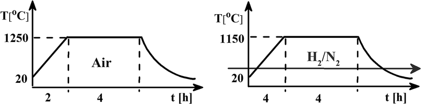 | ||
| Fig. 1 Scheme of the synthesis steps. | ||
The qualitative and quantitative phase composition of all samples was examined based on X-ray diffraction method (XRD) using a BRUKER D2PHASER diffraction equipment employing Cu Kα beam source and operating at 30 kV and 10 mA. The XRD patterns were collected using a scanning step of 0.02° and counting time of 0.4 s per step.
The luminescence (PL) and luminescence excitation spectra (PLE) at room temperature (RT) were measured using the Horiba spectrofluorometer FluoroMax-4P TCSPC produced by Horiba. The excitation light source was a xenon lamp 150 W emitting in the 220–800 nm range.11,14 The experimental setup for luminescence kinetics and time resolved emission spectra consists of YAG:Nd laser of PL 2143 A/SS type and the parametric optical generator PG 401/SH (OPG).17 The laser generated pulses of the 355 nm wavelength with frequency 10 Hz and pump PG generator which could produce light pulses with wavelength ranging from 220 nm to 2200 nm. The halfwidth of the time profile of the light pulse produced by an excitation source under experimental conditions is 44 ps and includes the half time of the light pulse duration produced by the OPG coupled to the YAG:Nd laser and the time response of the detector. Emission signal was analyzed by the spectrometer 2501S (Bruker Optics) and a Hamamatsu Streak Camera model C4334-01 with a final spectral resolution of about 0.47 nm. Time resolved luminescence spectra were obtained by integration of streak camera images over time intervals, whereas luminescence decays were obtained by the integration of streak camera images over the wavelength intervals. Samples were cooled by an APD Cryogenics closed-cycle DE-202 optical cryostat, which allows a varying temperature between 10 K and 600 K.
Results and discussion
The XRD patterns of materials obtained before and after the reduction process are shown in Fig. 2. The good agreement of the obtained patterns with PDF 00-048-0402 standard indicates that the products are characterized by the pure phase of Ca9Y(PO4)7 and the other phases are not present in the materials. Moreover, the reduction process, as well as co-doping of the matrix, does not significantly change the structure of the host (the positions and relative intensities of the XRD signals are not changed with increasing Al3+ concentration). It is worth noting that in the case of sample co-doped with 5% of aluminum after reduction the slight broadening of signals can be seen. This effect could be due to many reasons and need more investigations. However, it was observed also in previous study for the samples after reduction.14 The obtained results show the Pechini method is very suitable to obtain well defined phosphors. The signal at 50.42 degree of 2θ is attributed to the apparatus artefact.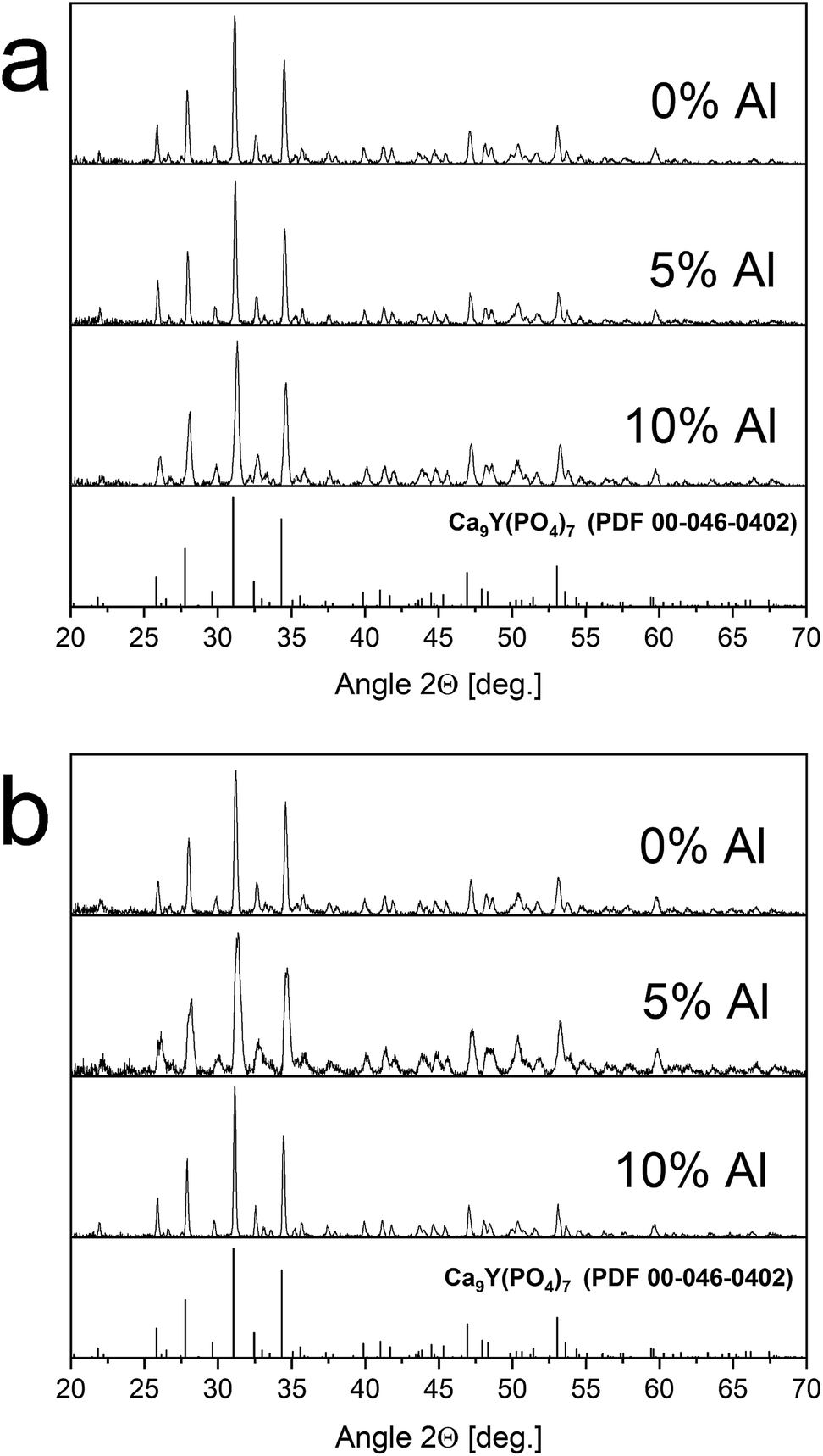 | ||
| Fig. 2 XRD patterns of Ca9Y(PO4)7:5% Eu; x% Al3+ (x = 0, 5, 10) before – (a) and after – (b) reduction. | ||
The Fig. 3 shows the normalized, partial luminescence excitation spectra (PLE) as well as the luminescence (PL) spectra of the materials activated by Eu3+ (materials obtained before the reduction process). As it can be seen in Fig. 3, the line shape of the emission spectrum as well as the excitation spectrum depends on the value of excitation and emission wavelength, respectively. Moreover, the shape of the spectra does not depend on the concentration of Al3+. The observed emission spectra of all materials are defined by characteristic luminescent lines attributed to the f–f transitions in Eu3+ ions. The lines observed at 580–600 nm are attributed to 5D0 → 7F1; at 610–630 nm to 5D0 → 7F2; at 640–660 nm to 5D0 → 7F3; and at 680–710 nm to 5D0 → 7F4 transition. The largest differences between the emission spectra excited at 393 and 395 nm can be observed in the intensities of 5D0 → 7F1 emissions. In the case of the spectrum excited at 395 nm, the emitted lines located at 593 and 596 nm are clearly more intense in comparison to the lines in the spectrum under the excitation at 393 nm. This feature is observed for spectra of all materials independently of the aluminum concentration. It is well known that the ratio of emission intensity of the 5D0 → 7F2 to the 5D0 → 7F1 transitions can be used as a probe of symmetry of Eu3+ site (asymmetric ratio, R) and if the value increases, the inversion symmetry of europium site decreases.18–21 Value of R calculated using emission intensities is equal to 5 and 3 for the spectra excited at 393 and 395, respectively. Due to the fact that the symmetry of calcium sites is described as C1 (less symmetrical) and yttrium sites – as C3, it can be concluded that the radiation equal to 395 nm excites mainly Eu3+ incorporated into the yttrium sites (Eu×Y), while the radiation of 393 nm excites mainly Eu3+ in Ca2+ sites  However, it is difficult to distinguish the emissions from individual calcium sites since they all have C1 symmetry.
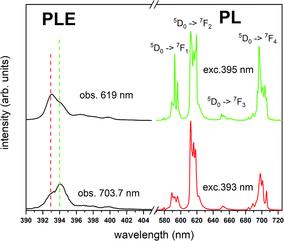 | ||
| Fig. 3 PL and partial PLE spectra of Ca9Y(PO4)7:Eu3+ measured at RT before the reduction. PLE spectra are recorded monitoring at 619 nm and 703.7 nm wavelength and collected under the excitation at 395 nm and 393 nm, respectively. | ||
The luminescence excitation spectra presented in the Fig. 3 show only the main differences between the individual spectra and are focused in the range of 390–405 nm. It can be observed that the maximum of excitation bands attributed to the 7F0 → 5L6 transition changes depending on the observation wavelengths, which is in agreement with the differences observed in emission spectra.
Fig. 4 shows the normalized spectra of Eu3+ PL attributed to 5D0 → 7F1 and 5D0 → 7F2 transitions obtained after excitation at 395 nm for the samples with different concentrations of aluminum before reduction. As it can be seen the intensity of the emission of 5D0 → 7F1 transition in comparison to the intensity of 5D0 → 7F2 transition slightly decreases with increasing Al3+ concentration. Because the ratio of the emission intensities of both transitions can be used to define the type of the occupied europium sites, the observed changes mean that the concentration of Eu3+ incorporated into the yttrium sites decreases with increasing aluminum content. This phenomenon can be explained considering the creation of charge compensation defects to keep the charge neutrality of the materials. Incorporation of Al3+ in the phosphorus sites creates negatively charged  defects. Due to the necessity to maintain charge neutrality of phosphor matrices, the created excessive negative charge has to be compensated by the creation of positively charged defects. As it was evidenced previously, the incorporation of Eu3+ is realized in two different cationic sites attributed to the calcium and yttrium sites. The Eu3+ in yttrium(III) sites creates the electrically neutral defect: Eu×Y, while the introduction of Eu3+ into the calcium(II) site creates positively charged defect:
  Taking into account the created europium defects, only the latter one can be considered as a potential compensator of the negative charge of
  defects. When the concentration of
  increases, the system diminishes the negative charge by the incorporation of Eu3+ in divalent calcium sites, among other factors.
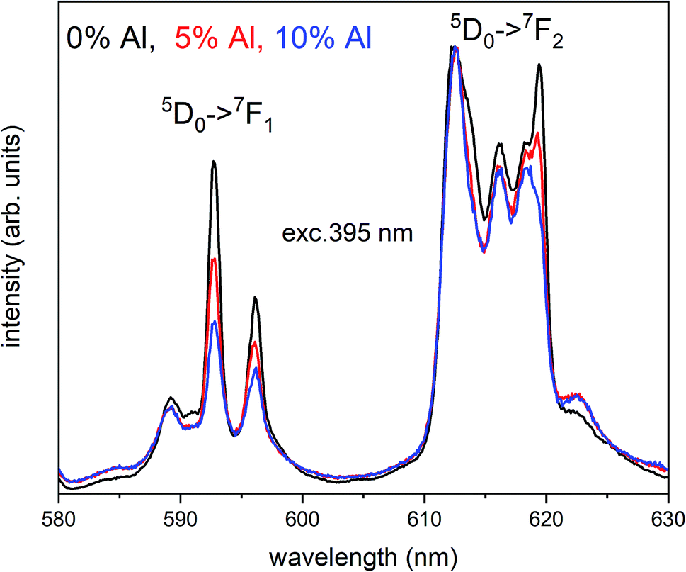 | ||
| Fig. 4 Normalized Eu3+ emission spectra of Ca9Y(PO4)7:Eu co-doped with al under 395 nm excitation. Presented emission is related to 5D0 → 7F1 and 5D0 → 7F2 transitions. | ||
The normalized emission and excitation spectra collected for the samples obtained after the reduction process are presented in Fig. 5. The luminescence of the samples consists of two separate emission bands with maximums located at 420 and 488 nm. As it can be seen there, the excitation wavelength (270 nm) corresponds to the intersection of both Eu2+ excitation spectra and is chosen since it excites the divalent europium ions independently of the europium(II) site occupation (Fig. 5).
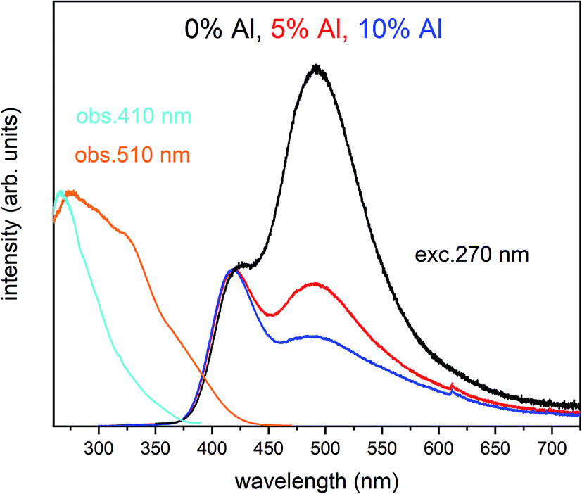 | ||
| Fig. 5 PL and partial PLE spectra of Ca9Y(PO4)7:5% Eu2+, x% Al3+ (x = 0, 5, 10%) measured at RT after the reduction. PLE spectra are recorded monitoring at 410 nm and 510 nm wavelength for all samples. The emission spectra were collected under excitation at 270 nm for all samples. | ||
The observed intensive and broad luminescence is characteristic of the d–f transitions in Eu2+ ions. Here, the relative intensity of both emission bands clearly depends on the Al3+ concentration. In the case of the un-co-doped material, the band with a maximum at 488 nm dominates, while in the materials co-doped with Al3+ the emission intensity of this band decreases with increasing aluminum concentration. The existence of two emission bands suggests that the Eu2+ ions are incorporated into at least two different sites characterized by a different arrangement of ligands surrounding the europium centres.
In accordance with previous studies22,23 the typical emission band of Eu2+ incorporated in Ca9Y(PO4)7 is observed with a maximum at 488 nm. However, other positions of the Eu2+ band were also observed after a modification of the phosphor matrix.24 Similar spectra as presented in Fig. 5 with both emission bands of Eu2+ located at 420 and 488 nm was observed in the case of Ca9Y(PO4)7:Eu modified in the stoichiometry of the matrix (changed Ca/Y concentration ratio).14 The presence of the band with the maximum at 420 nm was explained there as a result of Eu2+ environment changing due to the short distance compensation of negatively charged 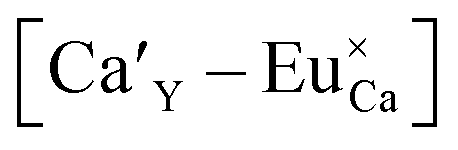 defects by the oxygen vacancies
 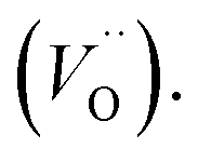 Here, as it can be seen in Fig. 5, the emission band is also present and moreover the intensity of the band increases with increasing aluminum concentration.
The reduction of Eu3+ occurs when the negative compensator of 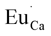 is locally neutralized.12–15 The neutralization process can be attributed to the physical elimination of the compensator from the surroundings of Eu3+ or to the emergence of another positively charged defect in the surroundings of the compensator. When the concentration of aluminum increases, the compensation of Eu3+ via the
  becomes more probable, thus, naturally created compensators of europium, e.g.
 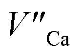 are exchanged for the chemically induced
  The process is the most probable in the sample doped with 10% of aluminum, however, even in this case the presence of natural compensators of europium
  cannot be excluded. Due to the presence of two different compensators of Eu3+ ions, the reduction process will be performed differently and will depend on the type of europium(III) compensation. In the case of Eu3+ compensated by the calcium vacancy, the reduction can be easily performed due to the high mobility of the defect and will occur when the compensator migrates from the vicinity of the europium. This process does not change the local environment of Eu2+ because the cation vacancy created as close as possible to the europium has to be located behind the oxygen surroundings of europium. The emission of Eu2+ reduced in such a way is attributed to the band with a maximum at 488 nm. The reduction process of Eu3+ compensated by the aluminum in the phosphorus site occurs differently. The
  compensators require much more activation energy to migrate across the crystal than cation vacancies because the additional interstitial stages have to be created during migration. It means that this compensator cannot be easily eliminated from the vicinity of the europium. However, the reduction of
  species can occur when the negative charge of
  remaining after the reduction will be locally compensated by the positively charged defects. This takes place when the oxygen vacancies, created during the reduction process on the surface of phosphor particles, migrate from the surface to the bulk crystal (to the environment of
  species). The presence of oxygen vacancy near the Eu2+ site changes the local structure of the emission center and diminishes the number of europium coordinated oxygen ligands. The crystal field of the site decreases and the emission band of Eu2+ is blue-shifted (band with the maximum at 420 nm). Such an effect was observed by Fang et al. in BaMgSiO4:Eu and has been attributed to the creation of oxygen vacancy in the first coordination sphere of an europium ion.25 Moreover, the Eu2+ emission located at 420 nm is typical for the europium doped Ca3(PO4)2 where the coordination number of cationic sites is defined as one less than in the case of Ca9Y(PO4)7 matrix. Due to the high strength of interactions between the oxygen and phosphorus ions the migration rate of oxygen vacancies is much smaller than in the case of cationic vacancies, e.g.
  It means that the reduction process via the migration of oxygen vacancies is less efficient.
The above presented explanation describes the situation when the aluminum ions are incorporated into the phosphate matrix. However, it can be seen in the Fig. 5 that the shoulder of the emission band with a maximum at 420 nm is also presented in the un-co-doped sample. This suggests that also in this case a part of Eu3+ ions is reduced via the migration of oxygen vacancies in a similar compensation mechanism as in the co-doped samples. This effect was also observed in [ref. 14] for the stoichiometric material where the chemically induced compensation defects were not intentionally created. As it was mentioned above, europium ions, besides the calcium sites, were also incorporated into the yttrium sites. This incorporation caused the creation of following defects:  and e.g.
  to neutralize the excessive, positive charge. In that case, after the reduction of europium introduced into the calcium sites, the remaining negative charge tied with
  defect can be also compensated via oxygen vacancy migrated from the surface. This can occur because in this case the
  defect cannot be easily eliminated. Nevertheless, the observed phenomenon requires further investigation.
It is worth emphasizing here, that aluminum ions can be a part of the crystal lattice in one of the members of whitlockite type of phosphate and can be located instead of yttrium in Ca9Y(PO4)7. Introduction of aluminum into the studied matrix can locally create Ca9Al(PO4)7 domains, thus, the observed changes in Eu2+ emission could be attributed to the presence of europium ions in the mentioned domains. However, in accordance to the Wang et al.26 Meng et al.27 and Hou et al.28 the Eu2+ emission band in the Ca9Al(PO4)7 is centered at 445–450 nm. The location of the untypical Eu2+ emission band observed in this study (420 nm) is different from that in the quoted studies, moreover, it is the same as in the [ref. 14], where the band was observed for the sample with higher than stoichiometric concentration of calcium, e.g.: Ca9.5Y0.5(PO4)7. This confirms that the presence and impact of Ca9Al(PO4)7 domains on luminescent properties of studied materials can be neglected.
Due to the fact that the reduction mechanism based on the  migration is less efficient as well as the
  compensation defects cannot be easily eliminated from the vicinity of Eu3+, the Eu3+ emission should increase with increasing aluminum concentration. As we can see in the Fig. 5, besides the broad luminescence of Eu2+, a trace of very low intensity emission lines located at about 615 nm in materials co-doped with Al can also be distinguished at excitation with 270 nm. The signals are attributed to the 5D0 → 7F1 and 5D0 → 7F2 f–f transitions in Eu3+. However, the intensity of Eu3+ emission after excitation at 270 nm is very weak and it seems that it does not depend on the aluminum content. The influence of the aluminum concentration on the luminescence of Eu3+ after reduction was investigated using 393 nm excitation wavelength. The spectra collected at room temperature are presented in Fig. 6.
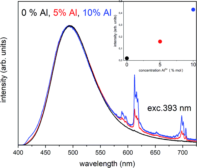 | ||
| Fig. 6 The normalized emission spectra of Ca9Y(PO4)7:5% Eun+, x% Al3+ (x = 0, 5, 10%) collected at RT after reduction under excitation at 393 nm for all materials. The relation between the Eu3+ intensity and Al3+ concentration is presented in the inset. | ||
The chosen excitation wavelength corresponds to the energy of 7F0 → 5L6 transition in Eu3+ and, thus, can effectively excite Eu3+ ions remained after the reduction. However, due to the strong overlapping of the Eu3+ and Eu2+ excitation bands, besides the Eu3+, the used wavelength also effectively excites the Eu2+ with a maximum of emission at 488 nm, which is seen in the Fig. 6. Nevertheless, it can be seen that the overall Eu3+ emission intensity increases with increasing aluminum concentration. The Eu3+ preservation phenomenon can be attributed to the mechanism described above. The created  defects play the role of
  compensators. As it was mentioned, the reduction Eu3+ requires the neutralization of compensating charge and in the case of
  the neutralization can be realized via migration of positively charged oxygen vacancies from the surface to the vicinity of the
  species. Because the migration rate of oxygen vacancies is low, the reduction process only partially occurs for Eu3+ ions compensated by aluminum defects. The residual Eu3+ emission observed after the reduction in the case of the un-co-doped sample can be attributed mainly to the Eu3+ incorporated into the yttrium sites (unreducible Eu×Y). Presence of the two Eu2+ emission bands is a result of different mechanisms of europium(III) reduction. The physical difference between these sites was studied by time-resolved spectroscopy using a streak camera.
According to the streak camera images, it is seen that the emission of Ca9Y(PO4)7:5% Eu without Al consists mainly of a broad band with a peak at 488 nm, related to the d–f transition in the Eu2+ ions occupying Ca2+ sites with unchanged surrounding (Fig. 7a), while in the case of the sample co-doped with 10% Al, the emission consists of a band with a peak at 420 nm, related to the d–f transition in the Eu2+ ions occupying the sites with lower crystal field (Fig. 7b). Eu2+ emission with maximums at 420 and 488 nm are labelled as center II and I, respectively (Fig. 7c).
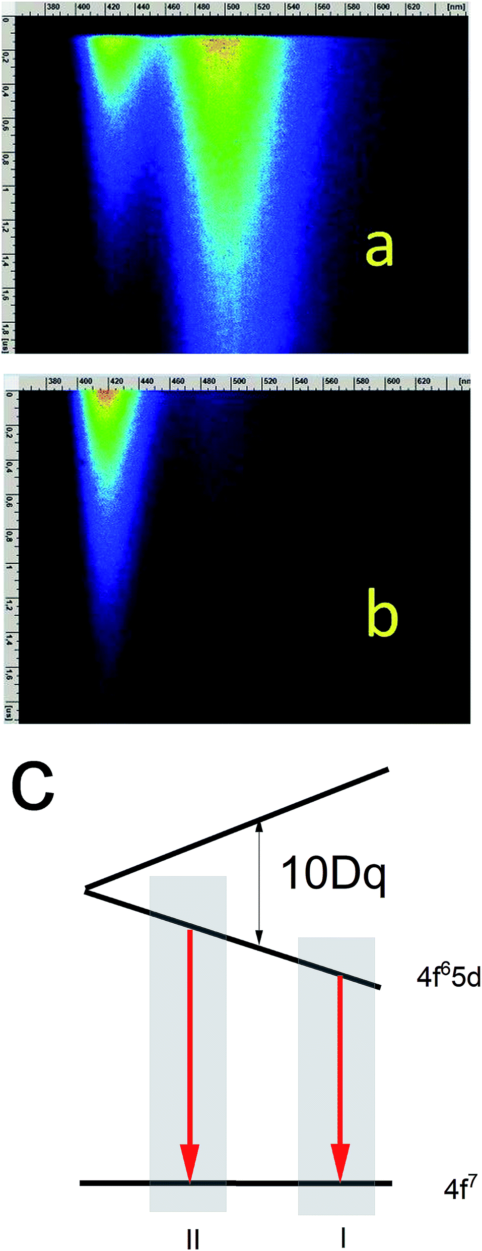 | ||
| Fig. 7 Streak images of Ca9Y(PO4)7:Eu2+, x% Al3+ at 10 K excited with 270 nm for acquisition times: 0–2 μs for samples without Al (a) and with 10% Al (b). Energetic structure of Eu2+ ions in low and high crystal field (c). | ||
The streak camera images allow to obtain PL decay. The results of the investigations are presented in Fig. 8–11.
 | ||
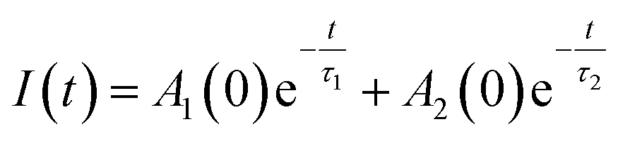
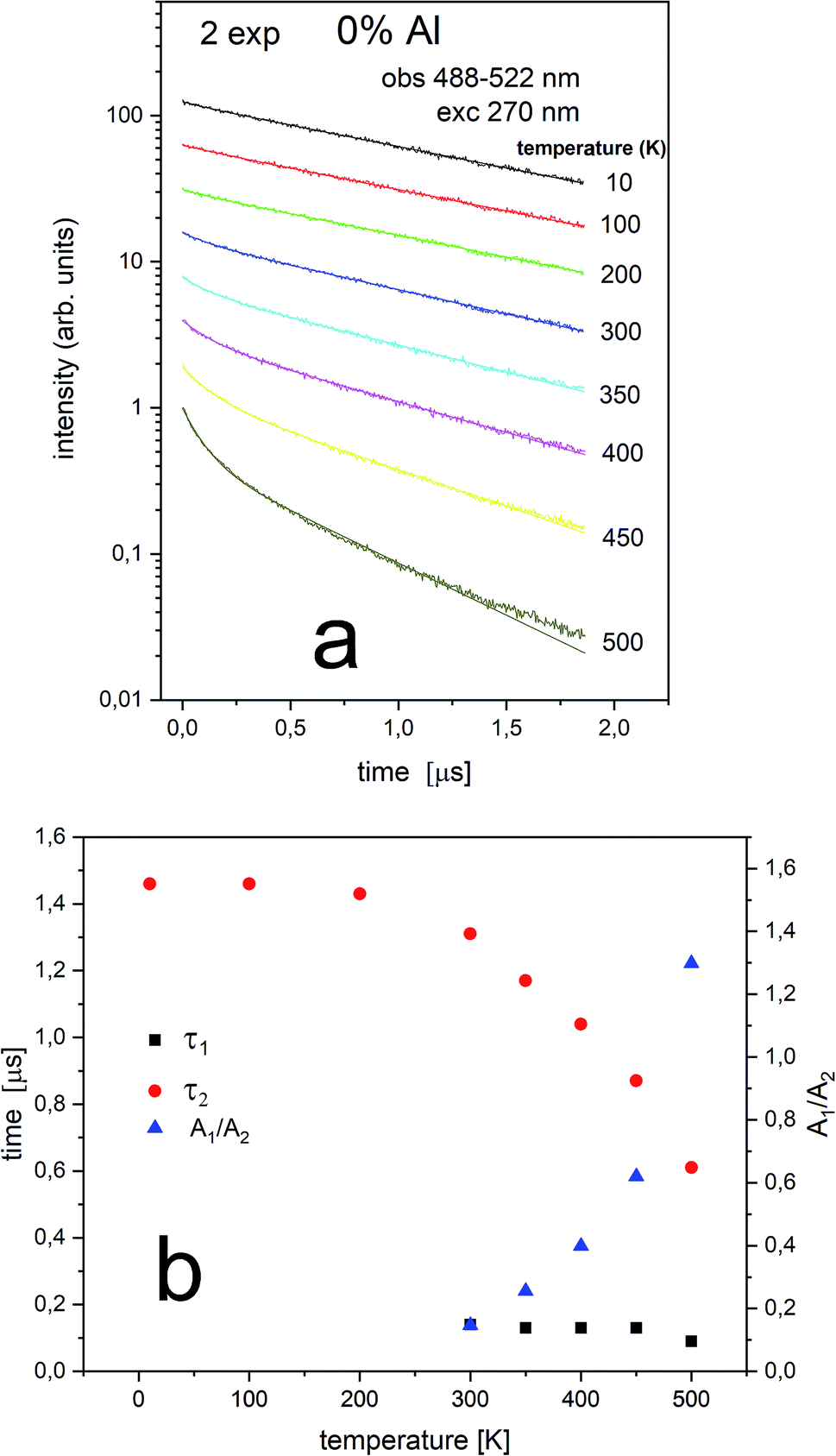
| Fig. 8 Luminescence decays obtained with 270 nm at different temperatures for 0% Al observed at 410–430 nm center II (a) as well as luminescence decay constants of both decay times (τ1 and τ2) and A1/A2 ratio measured at different temperatures (b). | ||
Generally, multiexponential decays are observed. This effect can be attributed to the nonradiative energy transfer between the centers. For simplicity we assumed two exponential character of the decays, thus, the obtained curves were fitted using the two exponential function given by (1):
 | (1) |
The Eu2+ luminescence decay profiles of the un-co-doped (0% Al3+) samples under excitation at 270 nm and luminescence monitoring at 410–430 nm (center II) and 488–522 nm (center I) were collected in Fig. 8 and 9, respectively.
From Fig. 8 a multiexponential decay is seen. For analysis we assumed double exponential decay (given by relation (1)). With the shorter decay, the constant changes between 0.1 and 0.2 μs and for the longer decay it is equal to 0.5–0.7 μs.
From Fig. 9 it is seen that PL decay is single exponential for temperature lower than 200 K. For higher temperature, the multiexponential decay is seen and for analysis we assumed two exponential decay (given by relation (1)). The slower decay time distinctly decreases with increasing temperature (see Fig. 9b). The decays have two-exponential character with the shorter decay constant equal to 0.1–0.11 μs and the longer – equal to 1.5–0.65 μs. It is seen from Fig. 8a, b, 9a and b that luminescence related to center II decays faster than the emission of center I. That is in accordance with the quantum mechanical rule, where emission with higher energy decays with shorter decay time.
 | ||
| Fig. 9 Luminescence decays obtained with 270 nm at different temperatures for 0% Al observed at 484–522 nm (center I) (a) and luminescence decay constants of both decay times (τ1 and τ2) measured at different temperatures as well as the ratio of A1/A2 (b). | ||
The PL decay profiles of center II and center I in the sample co-doped with 10% Al3+ obtained at different temperatures under excitation 270 nm, monitored at 410–430 nm and 484–522 nm are presented in Fig. 10a and 11a, respectively. In Fig. 10a, the decay of the luminescence of center II is presented. Two exponential decay is observed. The shorter decay is equal to 0.04–0.07 μs and the longer decay is equal to 0.74–0.55 μs. It is seen that the longer decay time related to center II in the samples un-doped and co-doped with aluminum is approximately the same. In Fig. 11a, the decay of the luminescence of center I is presented. Here as in the case of center II two exponential decay is observed. The shorter decay is equal to 0.02–0.05 μs and the longer decay is equal to 0.74–1.44 μs. The slower decay time decreases with increasing temperature (see Fig. 11b). It is seen that the longer decay time related to center I in the samples un-doped and co-doped with aluminum is approximately the same. The longer decay time of PL of center I decreases with increasing temperature in doped and un-doped samples. This effect is related to increasing probability of the nonradiative recombination with the temperature.
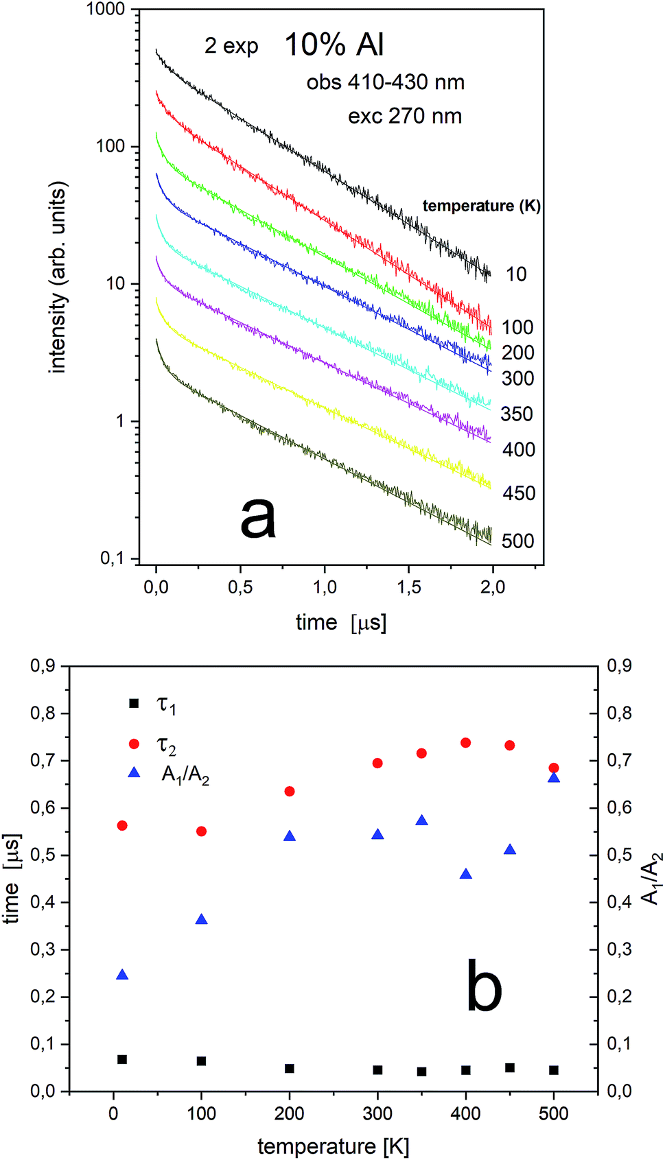 | ||
| Fig. 10 Luminescence decays obtained with 270 nm at different temperatures for 10% Al observed at 410–430 nm center II (a) and luminescence decay constants of both decay times (τ1 and τ2) measured at different temperatures (b). | ||
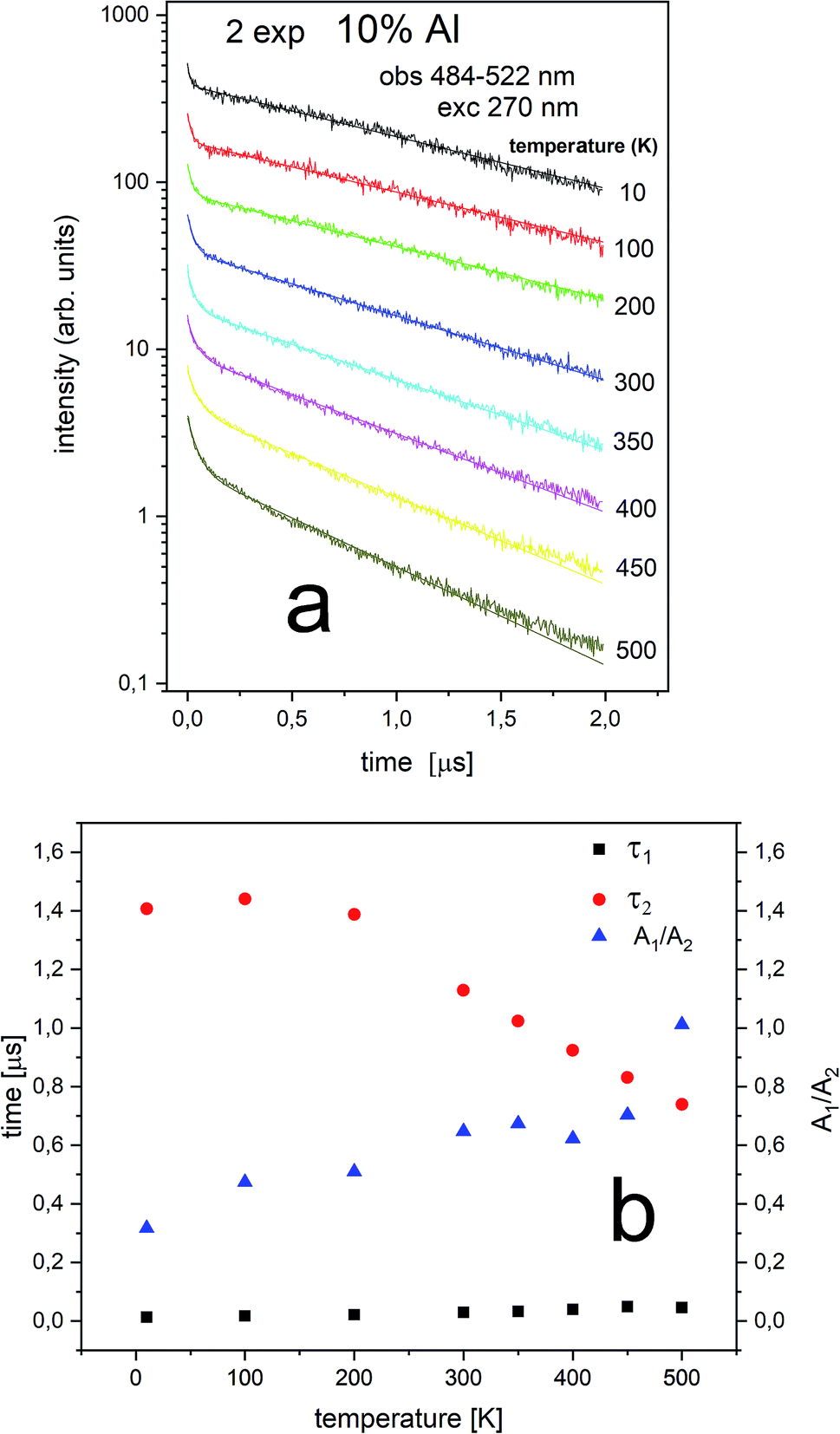 | ||
| Fig. 11 Luminescence decays obtained with 270 nm at different temperatures for 10% Al observed at 484–522 nm (a) and luminescence decay constants of both decay times (τ1 and τ2) measured at different temperatures (b). | ||
Independently of the aluminum concentration, the change of decay times calculated from the longer component of the decays (τ2) and obtained for the monitoring range 410–430 nm (center II) shows untypical behavior vs. temperature (Fig. 8b and 10b). It can be observed that in low temperatures (10–100 K) the decay time decreases, then, between 200–400 K, the time increases and above 400 K slightly decreases with temperature. The effect of increasing the longer lifetime in the case of center II in the 100–400 K temperature range is related to overlapping of I and II centers emission with temperature that is illustrated in Fig. 12.
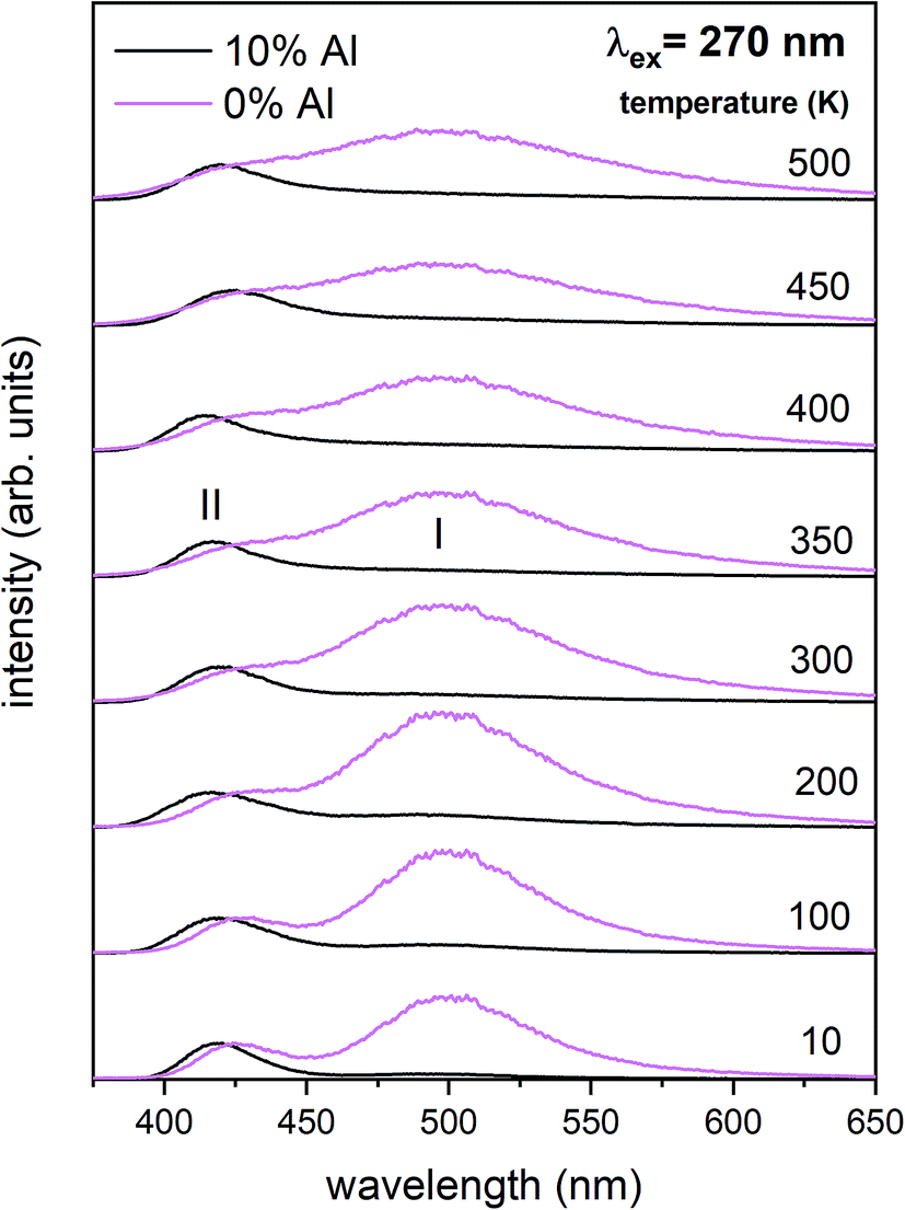 | ||
| Fig. 12 Luminescence spectra obtained from streak camera images at different temperatures (10–500 K) for the un co-doped (pink) and 10% Al co-doped (black) samples. | ||
Conclusions
As it was mentioned in the introduction, the aim of the studies was to investigate the influence of aluminum co-doping on the luminescent properties of europium doped Ca9Y(PO4)7 and to compare the observed influence of the presence of Al3+ with the results obtained in previous work [ref. 14] that concerned influence of stoichiometry changing of phosphate matrix on the luminescence of europium ions.The europium ions incorporated into the matrix occupy at least two different crystallographic sites. It is important to point out that the sites occupied by the Eu3+ are not the same as the sites occupied by the Eu2+. In the case of Eu3+, the sites are characterized by a different degree of inversion symmetry. Considering the symmetry of cationic sites in the matrix, it is concluded that europium ions are incorporated into calcium (without inversion symmetry) and yttrium (with inversion symmetry) sites. The distribution of europium ions among the sites with different symmetry depends on the aluminum content and the filling of calcium sites increases with increasing Al3+ concentration. In the case of Eu2+, two emission bands are observed: the typical one centered at 488 nm (center I) and untypical – at 420 nm (center II). The intensity of europium emission in center II increases with increasing aluminum concentration. However, in contrast to Eu3+, the two observed bands are attributed to Eu2+ incorporated only into the calcium sites. The two bands are the result of the presence of two different Eu3+ compensators  thus, the reduction process occurs in two different ways. It is worth noting that the europium(III) ions occupying yttrium sites remain unreduced, which is observed in the un-co-doped sample.
The most important effect of introduction of aluminum ions into the system is stabilization of Eu3+ under reductive conditions. This phenomenon is attributed to the difference in mobility of  compensators. In the case of
  compensated via
  the reduction process is less efficient due to the lower mobility of
  in comparison to
  and the europium ions compensated by the
  are mostly unreduced.
Moreover, the similarity between the results obtained in the previous study, [ref. 14], and the results obtained in this work (the presence of the untypical emission of Eu2+ as well as the stabilization of Eu3+ under reductive atmosphere) using a different strategy of compensation, clearly confirms that chemically induced negatively charged compensation defects play a fundamental role in the mechanism of lanthanides reduction in the studied system.
As far as the results of time resolved spectroscopy are concerned, it can be concluded that two different nonradiative transitions take place. In both cases (center II and center I) the nonradiative transfer between the centers is observed. This effect increases with increasing temperature and causes two-exponential decay of PL. The second kind of transition is nonradiative quenching, which is dominant in the case of center I.
Conflicts of interest
There are no conflicts to declare.Acknowledgements
This work was supported by the National Centre for Research and Development by grant no. PL-TW/V/1/2018.Notes and references
- E. F. Schubert and J. K. Kim, Science, 2005, 308, 1274 CrossRef CAS.
- S. Chawla, T. Roy, K. Majumder and A. Yadav, J. Exp. Nanosci., 2014, 9, 776 CrossRef CAS.
- K. S. Sohn, S. S. Kim and H. D. Park, Appl. Phys. Lett., 2002, 81, 1759 CrossRef CAS.
- J. Lee, S. Choi, S. Nahm and H.-K. Jung, Korean J. Mater. Res., 2014, 24, 351 CrossRef CAS.
- M. A. Lim, J. K. Park, C. H. Kim and H. D. Pa, J. Mater. Sci. Lett., 2003, 22, 1351 CrossRef CAS.
- Z. Xinmin, W. Hao, Z. Heping and S. Qian, J. Rare Earths, 2007, 25, 701 CrossRef.
- L. Chang, Z. Bi, H. Lüyuan and X. Xin, J. Rare Earths, 2014, 32, 691 CrossRef CAS.
- L. Yang, N. Zhang, R. Zhang, B. Wen, H. Li and X. Bian, Mater. Lett., 2014, 129, 134 CrossRef CAS.
- C. Guoa, L. Luan, C. Chen, D. Huang and Q. Su, Mater. Lett., 2008, 62, 600 CrossRef.
- Z. S. Khan, N. B. Ingale and S. K. Omanwar, AIP Conf. Proc., 2018, 1953, 070024 CrossRef.
- A. Baran, J. Barzowska, M. Grinberg, S. Mahlik, K. Szczodrowski and Y. Zorenko, Opt. Mater., 2013, 35, 2107 CrossRef CAS.
- K. Szczodrowski, J. Barzowska, N. Górecka and M. Grinberg, RSC Adv., 2016, 6, 48001 RSC.
- N. Gorecka, K. Szczodrowski, A. Lazarowska and M. Grinberg, New J. Chem., 2019, 43, 3409 RSC.
- N. Górecka, K. Szczodrowski, A. Lazarowska, J. Barzowska, D. Michalik and M. Grinberg, RSC Adv., 2017, 7, 40549 RSC.
- K. Szczodrowski, J. Barzowska, N. Gorecka and M. Grinberg, J. Alloys Compd., 2018, 748, 44 CrossRef CAS.
- A. Watras, P. J. Deren, R. Pazik and K. Maleszka-Bagińska, Opt. Mater., 2012, 34, 2041 CrossRef CAS.
- A. A. Kubicki, P. Bojarski, M. Grinberg, M. Sadownik and B. Kuklinski, Opt. Commun., 2006, 269, 275 CrossRef.
- G. Gao and L. Wondraczek, Opt. Mater. Express, 2014, 4, 477 Search PubMed.
- C. Hazra, S. Sarkar, B. Meesaragandla and V. Mahalingam, Dalton Trans., 2013, 42, 11981 RSC.
- M. Upasani, J. Adv. Ceram., 2016, 5, 344 CrossRef CAS.
- I. E. Kolesnikov, A. V. Povolotskiy, D. V. Mamonova, E. Yu. Kolesnikov, A. V. Kurochkin, E. Lähderanta and M. D. Mikhailov, J. Rare Earths, 2018, 36, 474 CrossRef CAS.
- H. Li, H. K. Yang, B. K. Moon, B. C. Choi, J. H. Jeong, K. Jang, H. S. Lee and S. S. Yi, Opt. Mater. Express, 2012, 2, 443 CrossRef CAS.
- C.-H. Huang, L. Luo and T.-M. Chen, J. Electrochem. Soc., 2011, 158, J341 CrossRef CAS.
- Z. Xia, H. Liu, X. Li and C. Liu, Dalton Trans., 2013, 42, 16588 RSC.
- W. Ji, M.-H. Lee, L. Hao, X. Xu, S. Agathopoulos, D. Zheng and C. Fang, Inorg. Chem., 2015, 54, 1556 CrossRef CAS.
- D. Wang, X.-Y. Meng, J.-W. Zhao, Y.-B. Wang, Y.-D. Zhang, Z.-J. Wang, S.-J. Gao, K. Zhang and P.-L. Li, Acta Photonica Sin., 2015, 44, 05160021 Search PubMed.
- X.-Y. Meng, X. Jie, Y.-D. Zhang, D. Wang, Y.-B. Wang, P.-L. Li, Z.-J. Wang, L.-B. Pang and S.-J. Gao, Optoelectron. Lett., 2015, 11, 0045 CrossRef.
- J. Hou, C. Pan, X. Chen, G. Zhao, Y. Liu, Y. Li and Y. Fang, Mater. Technol., 2019, 34, 135 CrossRef CAS.
| This journal is © The Royal Society of Chemistry 2020 |