 Open Access Article
All-solid-state flexible supercapacitor based on nanotube-reinforced polypyrrole hollowed structures†
Hyungho Kwon,
Dong Jin Han and
Byung Yang Lee *
*
Department of Mechanical Engineering, Korea University, Seoul 02841, Korea. E-mail: blee@korea.ac.kr
First published on 13th November 2020
Abstract
Supercapacitors are strong future candidates for energy storage devices owing to their high power density, fast charge–discharge rate, and long cycle stability. Here, a flexible supercapacitor with a large specific capacitance of 443 F g−1 at a scan rate of 2 mV s−1 is demonstrated using nanotube-reinforced polypyrrole nanowires with hollowed cavities grown vertically on a nanotube/graphene based film. Using these electrodes, we obtain improved capacitance, rate capability, and cycle stability for over 3000 cycles. The assembled all-solid-state supercapacitor exhibits excellent mechanical flexibility, with the capacity to endure a 180° bending angle along with a maximum specific and volumetric energy density of 7 W h kg−1 (8.2 mW h cm−3) at a power density of 75 W kg−1 (0.087 W cm−3), and it showed an energy density of 4.13 W h kg−1 (4.82 mW h cm−3) even at a high power density of 3.8 kW kg−1 (4.4 W cm−3). Also, it demonstrates a high cycling stability of 94.3% after 10![[thin space (1/6-em)]](https://www.rsc.org/images/entities/char_2009.gif) 000 charge/discharge cycles at a current density of 10 A g−1. Finally, a foldable all-solid-state supercapacitor is demonstrated, which confirms the applicability of the reported supercapacitor for use in energy storage devices for future portable, foldable, or wearable electronics.
000 charge/discharge cycles at a current density of 10 A g−1. Finally, a foldable all-solid-state supercapacitor is demonstrated, which confirms the applicability of the reported supercapacitor for use in energy storage devices for future portable, foldable, or wearable electronics.
Introduction
The development of efficient energy storage systems (ESSs) is becoming increasingly important as a result of the growing demand for reliable, sustainable, and clean energy sources for use in electric vehicles, smart-grid systems, and portable devices.1–5 Supercapacitors, in particular, are strong candidates for ESSs owing to their high power density, fast charge–discharge rate, and long cycle stability.5–7 For example, in the rapidly growing field of wearable electronics, all solid-state flexible supercapacitors exhibit promising performance as stable power supplies because of their excellent capability for electrochemical performance, light weight, and mechanical flexibility.8–11 However, the development of such supercapacitors requires electrode materials that have high specific surface area, conductivity, and mechanical stability.12,13 To this end, conductive polymers such as polyaniline, polythiophene, and polypyrrole (PPy) have been actively investigated because of their low cost and excellent electrochemical properties.6,14,15 Among these polymers, PPy has attracted significant attention owing to its flexible characteristics, environmental stability, and high mass density.16 Researchers have attempted to enhance the electrochemical performances of PPy-based electrodes by utilizing diverse structural forms such as nanofibers, nanotubes, and nanowires.17–19 However, significant volume changes in the PPy nanostructures during the charging/discharging process cause cyclic stability problems, which can limit their applications in stable supercapacitors.20 In order to overcome this limitation, hybrid structures comprising PPy and other carbon-based materials such as carbon nanotubes (CNTs) have been explored to alleviate volume swelling/de-swelling effect, and to afford therefore improved cycle stability.21–24 For example, electrodes based on PPy electrodeposited on CNT networks or meshes have been already demonstrated.25,26 However, these electrodes displayed relatively low capacitance values owing to their high electrode resistance and reduced specific surface area. In addition, this type of electrode requires the use of conductive additives and binders, which usually results in increased mass and weight. Consequently, there is a strong need for the development of an all-solid-state supercapacitor that does not require conductive additives and binders.Herein, we report an all-solid-state foldable supercapacitor with high specific capacitance, cycle stability, and mechanical stability. This performance is accomplished through several key steps, involving (i) the development of nanotube-reinforced hollowed PPy NWs (NTPPy NWs) with a high surface area and mechanical stability, (ii) vertical alignment of the NWs for large specific surface area and optimized ion diffusion path,27 and (iii) the use of flexible carbon-based materials for high mechanical flexibility. The fabricated electrodes exhibit excellent flexibility (a bending angle of 180°), high specific capacitance of 443 F g−1 at a scan rate of 2 mV s−1, and enhanced cycle stability. The symmetric supercapacitor structure fabricated using these electrodes requires no binder, no conductive additives, nor metals. The supercapacitor delivers a maximum specific and volumetric energy density of 7 W h kg−1 (8.2 mW h cm−3) at a power density of 75 W kg−1 (0.087 W cm−3), and it shows an energy density of 4.13 W h kg−1 (4.82 mW h cm−3) even at a high power density of 3.8 kW kg−1 (4.4 W cm−3). Also, it demonstrates a high cycling stability of 94.3% after 10![[thin space (1/6-em)]](https://www.rsc.org/images/entities/char_2009.gif) 000 charge/discharge cycles at a current density of 10 A g−1, demonstrating excellent long-term cycle stability. We expect that the strategy presented in this work could serve as a design framework for enhancing the capacitance and cyclic performance of PPy-based flexible superconductors.
000 charge/discharge cycles at a current density of 10 A g−1, demonstrating excellent long-term cycle stability. We expect that the strategy presented in this work could serve as a design framework for enhancing the capacitance and cyclic performance of PPy-based flexible superconductors.
Experimental procedure
Chemicals
CNTs (CoMoCat synthesis, (6, 5) chirality, carbon ≥99%, average diameter = 0.78 nm), sodium dodecyl sulfate (SDS, ACS reagent ≥ 99%), sodium dodecylbenzenesulfonate (SDBS, technical grade), pyrrole (reagent grade, 98%), and (3-aminopropyl)triethoxysilane (ACS reagent ≥ 98.5%) were purchased from Sigma Aldrich (USA). Graphene oxide (GO) powder (particle size: 6.63–27 μm) was purchased from Graphenea (USA). Anodized aluminium oxide membranes (AAO, Anodisc, 47 mm diameter, pore size = 0.2 μm) were purchased from Whatman, UK. All reagents were used as received without further purification.Fabrication of CNT/rGO hybrid base
To prepare the CNT/GO mixed solution, CNTs were first dispersed in deionized (DI) water at a concentration of 0.1 mg mL−1 by adding 5 wt% of SDS. The CNT solution was sonicated for 4 h using a bath sonicator [IN-410, Hwashin, Korea]. Meanwhile, a GO solution at a concentration of 0.5 mg mL−1 in DI water was prepared via sonication for 1 h. Subsequently, 18 mL of the 0.1 mg mL−1 CNT solution and 0.4 mL of the 0.5 mg mL−1 GO solution were mixed and sonicated for 1 h.For the adsorption of CNTs on the AAO inner walls, 5 mL of the 0.1 mg mL−1 CNT solution were diluted in 250 mL of DI water. Next, the CNT solution was vacuum-filtered through the AAO membrane. The membrane was treated with O2 plasma for 10 min. Then, the membrane was amine-functionalized by immersing it in 1![[thin space (1/6-em)]](https://www.rsc.org/images/entities/char_2009.gif) :
:![[thin space (1/6-em)]](https://www.rsc.org/images/entities/char_2009.gif) 100 (v/v) solution of APTES in ethanol for 1 h. The membrane was thoroughly washed with ethanol to remove any residual APTES. Finally, the CNT/GO mixed solution (9
100 (v/v) solution of APTES in ethanol for 1 h. The membrane was thoroughly washed with ethanol to remove any residual APTES. Finally, the CNT/GO mixed solution (9![[thin space (1/6-em)]](https://www.rsc.org/images/entities/char_2009.gif) :
:![[thin space (1/6-em)]](https://www.rsc.org/images/entities/char_2009.gif) 1, wt/wt%) was vacuum-filtered through the above AAO film. Afterwards, reduction of GO to rGO (reduced GO) was performed by drying the filtered membrane for 3 h at 115 °C, and annealing it for 1 h at 250 °C under vacuum.
1, wt/wt%) was vacuum-filtered through the above AAO film. Afterwards, reduction of GO to rGO (reduced GO) was performed by drying the filtered membrane for 3 h at 115 °C, and annealing it for 1 h at 250 °C under vacuum.
Fabrication of NTPPy NWs, PPy NWs, and film PPy (FPPy)
A pyrrole solution was prepared by adding 139 μL of pyrrole into 10 mL of 0.1 M SDBS solution in DI water. The NTPPy NWs were electrodeposited using the above-prepared AAO as the working electrode using a potentiostat (Reference 600, Gamry Instruments, Inc.) by chronocoulometry method (0.6 V potential, Ag/AgCl electrode, Pt wire counter electrode). After electrodeposition, the AAO membrane was immersed in 1 M NaOH solution to dissolve the sacrificial AAO. Then, the NTPPy NW array was washed thoroughly with DI water and ethanol. The number of pores per area can be estimated to be between 8 × 10⁶ and 1.6 × 107 mm−2. The sample yield from each electrodeposition run was about 90%. The PPy NWs without CNTs were prepared by electrodepositing PPy NWs under the same conditions as above but using Au base layer instead of CNT/rGO base film. Subsequently, a 400 nm-thick Au layer (mass loading: 1.1 mg cm−2) was deposited thermally on one side of the AAO filter to serve as the working electrode. The planar PPy film (FPPy) was electrodeposited under the same conditions as described earlier, but on a planar CNT/rGO base.Fabrication of all-solid-state symmetric supercapacitor based on NTPPy NWs electrodes
The NTPPy NW film with CNT/rGO base was cut into a 1 × 1 cm2 size and attached to a polypropylene tape. Then, the film was electrically connected to a copper tape and reinforced with Ag paste. Subsequently, a gel electrolyte was applied between the electrodes. The gel electrolyte was prepared by first mixing 10 mL of DI water with 1 g H2SO4, and later adding 1 g of polyvinyl alcohol (PVA) to the solution at 85 °C. The mixture was stirred until the solution became clear. The gel electrolyte was cooled to room temperature and poured onto the film electrode. To remove any residual water, the electrodes were placed in a desiccator for 4 h. Two fully dried electrodes were assembled face to face to give the symmetric supercapacitor.Electrochemical properties of the electrodes and the symmetric supercapacitor
All electrochemical measurements were conducted using a potentiostat/galvanostat (Reference 600 and Interface 1000E, Gamry Instruments, Inc.). The nanostructured film of NTPPy hollowed NWs was cut into a 1 × 1 cm2 size. To measure the half-cell electrochemical performance using cyclic voltammetry (CV), current charge–discharge and cycling tests, and electrochemical impedance spectroscopy (EIS), a three-electrode electrochemical cell was prepared using a Ag/AgCl reference electrode, a Pt-wire counter electrode, and the working electrode (NTPPy NWs on CNT/rGO base). The electrochemical properties of the PPy NWs were measured in the same manner.Capacitance was calculated from the CV curve using eqn (1):
| Csc = ∫Ivdv/(ΔVmv) | (1) |
The gravimetric (CSG) and volumetric (CSV) capacitance values of the assembled symmetric supercapacitor were investigated in a two-electrode configuration (eqn (2) and (3)). The gravimetric energy density (ESG, W h kg−1) and power density (PSG, kW kg−1) were obtained using eqn (4) and (5). The volumetric energy density (EV, mW h cm−3) and power density (PV, W cm−3) values were obtained by using eqn (6) and (7), respectively.19,27,30
| CSG = 2IΔt/(mΔV) | (2) |
| CSV = CSGm/(Ad) | (3) |
| ESG = (1/8)CSGΔV2 | (4) |
| PSG = ESG/Δt | (5) |
| PSV = I/(Ad) | (6) |
| ESV = PSVΔt | (7) |
Characterization of CNT/rGO base, PPy NW, FPPy, and NTPPy NWs
The morphology of the electrodes was observed using a scanning electron microscope (Quanta 250 FEG, FEI) and transmission electron microscope (Tecnai G2 F30ST, FEI). The chemical compositions were characterized by Raman spectroscopy (LabRAM ARAMIS IR2 spectrometer, Horiba Jobin Yvon) and XPS analysis (Ulvac-phi, X-tool). We used a 532 nm diode laser as the excitation source for Raman signal measurement.Results and discussion
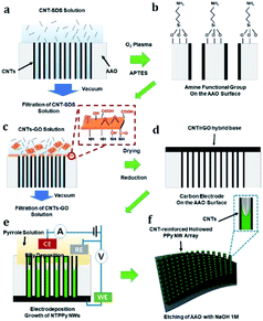
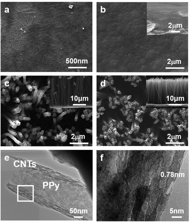
To fabricate the flexible supercapacitor electrodes based on NTPPy NWs, CNTs were first assembled on the sidewalls of the AAO pores (Fig. 1a) by vacuum-filtration of CNTs through an AAO template (pore diameter = 200 nm).31–33 The AAO surface was amine-functionalized to aid subsequent adsorption of the base film (Fig. 1b). Subsequently, a mixed solution of CNTs and GO was filtered to form the CNT/GO base film (Fig. 1c). Since GO has amphiphilic properties, the CNTs adsorbed well on the GO surface.34–36 The hydroxyl, carboxyl, and epoxyl groups present on the GO surface are known to aid the binding between GO and the amine groups on the AAO surface (Fig. S1†).37,38 In the next step, GO was thermally reduced to form a CNT/rGO base film electrode for subsequent NTPPy NW growth (Fig. 1d). The success of the thermal reduction was verified by analysis of the changes in the Raman spectra and sheet resistance before/after annealing (Fig. S2 and S3†). Subsequently, NTPPy NWs were grown by electrodeposition in the chronocoulometric mode. During the electrodeposition process, the CNTs adsorbed onto the AAO inner walls served as extended working electrodes,39 resulting in the growth of PPy NWs along the CNTs (Fig. 1e). We obtained the CNT-reinforced PPy NW hollowed structures by controlling the total electrodeposition charge. After the electrodeposition, the AAO template was removed using a basic NaOH solution (Fig. 1f).Fig. 2 shows the structural morphologies of four different types of films: CNT/rGO base film, FPPY film, PPy NW array, and NTPPy NW array. The CNT/rGO base film shows uniform entangled structures of CNTs and rGO (Fig. 2a). After electrodepositing PPy on the base film, we obtained an FPPy film structure with a thickness of ∼5.4 μm (Fig. 2b). In the case of PPy and NTPPy NW arrays, the NWs were vertically oriented with an outer diameter of ∼200 nm and length of ∼20 μm (Fig. 2c and d). However, these two arrays exhibited notable structural differences. While the PPy NWs displayed solid filled structures that were also observed by TEM (see Fig. S4†), the NTPPy NWs exhibited hollowed cavities at the end of each NW as shown in Fig. 2d. The hollowed structure is a direct consequence of electrodepositing PPy on CNTs adsorbed on AAO inner walls. We can see that the NTPPy NWs have well defined dimensions (average inner diameter of 180 nm and wall thickness of 30 nm) and show intimate adhesion between the CNTs and the PPy matrix (Fig. 2e and f). Typical TEM images of NTPPy NWs revealed that the CNTs had an average diameter of 0.78 nm.
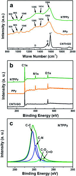
Raman spectra were recorded for the CNT/rGO hybrid, PPy NWs, and the NTPPy NW composite as shown in Fig. 3a. The CNT/rGO base displayed two prominent peaks at the G and D bands, respectively. The G band of the CNT/rGO film exhibited small-diameter characteristics typical for semiconducting CNTs grown by CoMoCat process.40,41 The remarkable separation of the G+ and G− modes as well as the <1540 cm−1 G− mode confirmed the sub-nanometer diameter of the semiconducting nanotubes. For the PPy NWs and NTPPy NWs, the characteristic bands corresponding to PPy were observed, indicating the successful electrodeposition of PPy on the CNT/rGO and the gold electrode. The ring deformation modes observed at 930 and 985 cm−1 reflected different oxidation steps of the pyrrole unit; the peak at 1046 cm−1 corresponds to C–H in-plane deformation; the peak at 1413 cm−1 is attributed to C–N stretching mode deformation; peaks at 1385 and 1584 cm−1 are attributed to the ring stretching mode of the polymer backbone and the p-conjugated structure.17 Moreover, the D and G bands arising from CNT/rGO at 1340 cm−1 and 1580 cm−1, respectively, overlapped with the peak arising from PPy in the hybrid composite.
Surface elemental analysis of the CNT/rGO base film and NTPPy NWs was also carried out by X-ray photoelectron spectroscopy (XPS) (Fig. 3b and c). In comparison to the full XPS spectrum of the CNT/rGO film, a clear signal associated with N was obtained for the NTPPy NWs, which can be attributed to the presence of PPy. The pristine PPy NWs had a higher N content (12.9%) than the CNT/rGO hybrid base and the NTPPy NWs. The higher N content of the NTPPy NWs (11.4%) when compared to the CNT/rGO base film electrode indicates the successful electrodeposition of PPy in the hybrid composite. The quantitative percentage of C, O, and N in the NTPPy NWs was 82.1%, 11.4%, 6.5%, respectively. The curve fitting results of C 1s spectra are shown in Fig. 3c. In the spectra of CNT/rGO paper and pristine PPy NWs, C–C bonding at 284.5 eV and C–N bonding at 285.5 eV were dominant, respectively (Fig. S5†). The spectrum of NTPPy NWs exhibited a peak characteristic for the C–N backbone with a binding energy of 285.5 eV, demonstrating the existence of PPy.
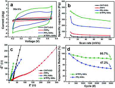
The electrochemical capacitance performance was measured for four types of electrodes, namely the CNT/rGO base film, FPPY film, PPY NW array, and NTPPy NW array. The specific capacitance was calculated from CV at scan rates ranging from 2 to 100 mV s−1.28,29 The CV curves of the four electrodes exhibited different shapes at the same scan rate (30 mV s−1). In the case of the NTPPy NW array, the CV curves displayed a quasi-rectangular shape and larger area compared to the other films. The specific capacitance of the NTPPy NW array electrode at a scan rate of 2 mV s−1 was 443 F g−1, and was thus considerably higher than that of the CNT/rGO base film (42.6 F g−1), FPPy (93 F g−1), and the PPy NW array (348 F g−1) (Fig. 4b). Furthermore, the NTPPy NW array electrode exhibited significantly increased capacitance retention compared to the other electrodes (Fig. S6†). This difference in capacitance performance can be attributed to the vertically aligned PPy nanostructure with high orientation is expected to provide high specific surface area and enhanced ion mobility, resulting in increased capacitance performance.42 In addition, since the CNT-reinforcement of the PPy NWs can provide an additional electron transfer pathway to the PPy NWs, it can increase the rate capability of the NTPPy NW film when compared to the other films.43,44
We observed a significantly enhanced cycling stability for the NTPPy NW array electrodes (Fig. 4c). After 3000 charge/discharge cycles at a current density of 10 A g−1, the NTPPy NW array retained 80.7% of its initial capacitance, while the PPy NW array retained only 47.2%. This enhanced cycling stability of the NTPPy NW array can be attributed to the mechanical reinforcement with CNTs, which prevents the PPy NWs from undergoing a large volume change, mechanical deformation, and PPy degradation during the long-term charge/discharge processes. Furthermore, the morphology of the PPy and NTPPy NWs were observed by SEM before and after 3000 charge/discharge cycle tests (Fig. S7†). Before the cycling tests, the PPy and NTPPy NWs clearly exhibited vertically aligned structures as shown in Fig. 2c. After 3000 charge/discharge tests, the PPy NWs showed aggregation into film-like structures. However, in case of the NTPPy NWs, they maintained their vertical alignment and hollowed structures (Fig. S7d†). These results confirm the role of CNT-reinforcement in enhancing structural stability and cycle performance.
Electrochemical impedance spectroscopy (EIS) analysis was conducted over the frequency range from 10 kHz to 0.01 Hz in order to find out more information about the internal resistance of each electrode, which is known to correlate with the conductivity and ion diffusion resistance (Fig. 4d). The low equivalent series resistance (ESR) from the high-frequency intercept on the real axis of the Nyquist plot indicates high electrode conductivity. The calculated ESRs were 20.4 Ω, 14.7 Ω, 5.5 Ω, and 6.0 Ω for the CNT/rGO, FPPy, PPy NW array, and the NTPPy NW array electrodes, respectively. The electrodeposition of PPy resulted in reduced ESR for the FPPy, PPy NW, and NTPPy NW electrodes. This behaviour is similar to that reported by Cherusseri et al. and Malik et al.21,42 In particular, the electrodes with vertically aligned NW structures such as NTPPy and PPy NW arrays exhibited lower active material resistance compared to CNT/rGO and FPPY films. In case of PPy NWs, the apparent low ESR of 5.5 Ω can be attributed to its structure, where the PPy NWs are deposited on highly conductive Au electrode. The impedance curves of the NTPPy NW electrodes were more vertical and closer to the imaginary axis in the low frequency region compared to the thin FPPy electrode, indicating improved charge transfer within the electrode and reduced ion diffusion resistance.45,46 These effects act synergistically to facilitate enhanced capacitive behaviour.
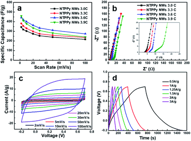
In order to determine the optimal PPy loading amount in the devices, we investigated the effect of PPy loading on the specific capacitance. To this end, electrodes with different PPy loadings were prepared by controlling the electrodeposition charge of PPy from 3.0C to 3.9C, resulting in different PPy mass loadings of 0.43, 0.47, 0.56, and 0.62 mg cm−2, respectively. As shown in Fig. 5a, the specific capacitance vs. scan rate curves for the samples with different PPy loadings show that the optimal deposition charge is 3.6C. The specific capacitance increases up to 3.6C, and subsequently begins to drop as the PPy load is increased beyond 3.6C. The reason for this result can be inferred from the Nyquist plot shown in Fig. 5a. We can see that the ESR increases with increasing PPy loading from 3.4 Ω to 9.5 Ω. A similar ESR trend has been reported previously by Tian et al. and Malik et al.42,47 In addition, the diameter of the semicircle in the Nyquist plot increases together with the PPy loading, which indicates that the charge transfer resistance also increases. This result might also explain the increase in the length of the NTPPy NWs with increasing PPy loading (Fig. S8†). Therefore, considering the specific capacitance and rate capability, all subsequent experiments performed in this work focused on samples that were prepared using the optimum PPy deposition charge of 3.6C.
The electrochemical capacitance performance of the as-prepared NTPPy NWs (3.6C) was evaluated by CV and galvanostatic charge/discharge techniques under the same conditions as described above. The CV curves in Fig. 5c show the rectangular and symmetric current–potential characteristics of these NTPPy NWs, which are close to the ideal capacitive behaviour.48 In addition, no clear redox peaks were observed in the potential range between −0.2 and 0.7 V. The rectangular shape is retained even at a high scan rate of 100 mV s−1, which indicates the capacitive nature of the electrodes. The galvanostatic charge/discharge curves measured at various current densities (Fig. 5d) exhibited a triangular shape and very small voltage drop during the charge/discharge process.
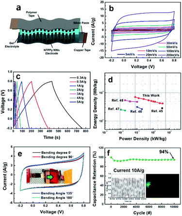
These results demonstrate that the NTPPy NW electrodes are indeed suitable for use in high performance supercapacitors. As a proof of concept, we assembled a flexible, all-solid-state supercapacitor device from the NTPPy NW array electrodes; this device is free from metals and binders, and is both lightweight and foldable. Two symmetric electrodes were assembled face to face and PVA/H2SO4 gel was used as the solid-state electrolyte and separator (Fig. 6a). Fig. 6b shows the nearly rectangular CV curves and increasing current density with increasing scan rate, which indicate the good rate capability of the symmetric supercapacitor.49 The galvanostatic charge/discharge curves at various current densities of 0.3–5 A g−1 in Fig. 6c exhibited a symmetrical triangular shape and low voltage drop. The specific and volumetric capacitance of the supercapacitor was measured to be 201.7 F g−1 (65.4 F cm−3) at the current density of 0.3 A g−1 (0.087 A cm−3), and the assembled supercapacitor retained a capacitance of 119.1 F g−1 (38.6 F cm−3) at a current density of 15 A g−1 (4.4 A cm−3) (Fig. S9a†). Since the CNT/rGO base contributes very little to the total mass (density of 0.14 mg cm−2) and the thickness of electrode was as small as ∼25 μm, the specific and volumetric capacitances of the device were higher than the values reported previously for flexible devices based on PPy structures integrated with CNTs or graphene.50,51 The ESR of the supercapacitor device was 5.73 Ω, and the quasi-vertical straight line observed at low frequency indicated an excellent capacitive behaviour (Fig. S9b†).
The symmetric capacitor exhibited a maximum gravimetric energy density of 7 W h kg−1 at a power density of 75 W kg−1, and it showed an energy density of 4.13 W h kg−1 even at a high power density of 3.8 kW kg−1. When plotted together, the energy density value of 7 W h kg−1 for our system is much higher than those of other conductive polymer-based devices described in previous reports (Fig. 6d).50–54 Moreover, it also has high volumetric energy density, from 8.2 mW h cm−3 at 0.087 W cm−3 to 4.82 mW h cm−3 at 4.4 W cm−3, higher than some previous reported values (Fig. S10†).54–58
In order to evaluate the mechanical flexibility of our supercapacitor, the device was operated under different bending angles at a CV scan rate of 50 mV s−1 (Fig. 6e). When compared to the flat state (bending angle of 0°), no obvious changes in CV curves were observed even at a bending angle of 180° (i.e., a bending radius of 0.61 shown in the inset of Fig. 6e). More importantly, this all-solid-state supercapacitor based on NTPPy NW arrays also exhibited a good long-term cycling stability, where more than 94.3% of its initial capacitance was retained after 10![[thin space (1/6-em)]](https://www.rsc.org/images/entities/char_2009.gif) 000 cycles at a current density of 10 A g−1 (Fig. 6f), confirming the positive effects of CNT-reinforcement in enhancing the cycling stability. Finally, the feasibility of utilizing this all-solid-state supercapacitor to power a small electronic device was evaluated. This experiment revealed that three devices connected in series successfully powered a green light-emitting diode (LED) (Fig. 6f, inset).
000 cycles at a current density of 10 A g−1 (Fig. 6f), confirming the positive effects of CNT-reinforcement in enhancing the cycling stability. Finally, the feasibility of utilizing this all-solid-state supercapacitor to power a small electronic device was evaluated. This experiment revealed that three devices connected in series successfully powered a green light-emitting diode (LED) (Fig. 6f, inset).
Conclusions
In summary, we demonstrated a foldable, high-performance all-solid-state supercapacitor based on CNT-reinforced PPy NW array electrodes. The CNTs assembled on AAO inner walls and a lightweight and flexible CNT/rGO base film enabled the fabrication of flexible electrodes that are suitable for flexible supercapacitors. The resultant NTPPy NW array electrode exhibited considerably enhanced and more stable electrochemical properties when compared to film electrodes or PPy NW arrays prepared without the CNTs. Moreover, a foldable, all-solid-state supercapacitor was demonstrated, confirming the applicability of our supercapacitor as an energy storage device for future portable, foldable, and wearable electronics.Conflicts of interest
The authors declare no conflict of interest.Acknowledgements
This project was supported by the National Research Foundation (NRF) funded by the Korea Ministry of Science and ICT (2018R1A2B2006640, 2016M3A7B4909581) and Global Frontier Project from the Center for Integrated Smart Sensors (CISS-2011-0031866).References
- D. P. Dubal, O. Ayyad, V. Ruiz and P. Gomez-Romero, Chem. Soc. Rev., 2015, 44, 1777–1790 RSC.
- B. Dunn, H. Kamath and J.-M. Tarascon, Science, 2011, 334, 928–935 CrossRef CAS.
- B. Joonho, S. M. Kyu, P. Y. Jun, K. J. Min, L. Meilin and W. Z. Lin, Angew. Chem., Int. Ed., 2011, 50, 1683–1687 CrossRef.
- Z. Yang, J. Zhang, M. C. W. Kintner-Meyer, X. Lu, D. Choi, J. P. Lemmon and J. Liu, Chem. Rev., 2011, 111, 3577–3613 CrossRef CAS.
- K. Zhang, L. L. Zhang, X. S. Zhao and J. Wu, Chem. Mater., 2010, 22, 1392–1401 CrossRef CAS.
- G. A. Snook, P. Kao and A. S. Best, J. Power Sources, 2011, 196, 1–12 CrossRef CAS.
- G. Wang, L. Zhang and J. Zhang, Chem. Soc. Rev., 2012, 41, 797–828 RSC.
- L. Dong, G. Liang, C. Xu, W. Liu, Z.-Z. Pan, E. Zhou, F. Kang and Q.-H. Yang, Nano Energy, 2017, 34, 242–248 CrossRef CAS.
- L. Hu, M. Pasta, F. La Mantia, L. Cui, S. Jeong, H. D. Deshazer, J. W. Choi, S. M. Han and Y. Cui, Nano Lett., 2010, 10, 708–714 CrossRef CAS.
- W.-w. Liu, X.-b. Yan, J.-w. Lang, C. Peng and Q.-j. Xue, J. Mater. Chem., 2012, 22, 17245–17253 RSC.
- D.-W. Wang, F. Li, J. Zhao, W. Ren, Z.-G. Chen, J. Tan, Z.-S. Wu, I. Gentle, G. Q. Lu and H.-M. Cheng, ACS Nano, 2009, 3, 1745–1752 CrossRef CAS.
- L. Chai, L. Zhang, X. Wang, L. Xu, C. Han, T.-T. Li, Y. Hu, J. Qian and S. Huang, Carbon, 2019, 146, 248–256 CrossRef CAS.
- X. Wang, A. Dong, Y. Hu, J. Qian and S. Huang, Chem. Commun., 2020, 56, 10809–10823 RSC.
- T. Liu, L. Finn, M. Yu, H. Wang, T. Zhai, X. Lu, Y. Tong and Y. Li, Nano Lett., 2014, 14, 2522–2527 CrossRef CAS.
- L. Yuan, B. Yao, B. Hu, K. Huo, W. Chen and J. Zhou, Energy Environ. Sci., 2013, 6, 470–476 RSC.
- Y. Huang, H. Li, Z. Wang, M. Zhu, Z. Pei, Q. Xue, Y. Huang and C. Zhi, Nano Energy, 2016, 22, 422–438 CrossRef CAS.
- S. Biswas and L. T. Drzal, Chem. Mater., 2010, 22, 5667–5671 CrossRef CAS.
- K. Shi and I. Zhitomirsky, J. Mater. Chem. A, 2013, 1, 11614–11622 RSC.
- C. Yang, L. Zhang, N. Hu, Z. Yang, H. Wei and Y. Zhang, J. Power Sources, 2016, 302, 39–45 CrossRef CAS.
- A. Kumar, R. K. Singh, H. K. Singh, P. Srivastava and R. Singh, J. Power Sources, 2014, 246, 800–807 CrossRef CAS.
- J. Cherusseri and K. K. Kar, J. Mater. Chem. A, 2016, 4, 9910–9922 RSC.
- F. M. Guo, R. Q. Xu, X. Cui, L. Zhang, K. L. Wang, Y. W. Yao and J. Q. Wei, J. Mater. Chem. A, 2016, 4, 9311–9318 RSC.
- Y.-J. Peng, T.-H. Wu, C.-T. Hsu, S.-M. Li, M.-G. Chen and C.-C. Hu, J. Power Sources, 2014, 272, 970–978 CrossRef CAS.
- L. Chai, Z. Hu, X. Wang, Y. Xu, L. Zhang, T. T. Li, Y. Hu, J. Qian and S. Huang, Adv. Sci., 2020, 7, 1903195 CrossRef CAS.
- H. Fu, Z.-j. Du, W. Zou, H.-q. Li and C. Zhang, J. Mater. Chem. A, 2013, 1, 14943–14950 RSC.
- B. Wang, J. Qiu, H. Feng and E. Sakai, Electrochim. Acta, 2015, 151, 230–239 CrossRef CAS.
- Y. Xu, Z. Lin, X. Huang, Y. Liu, Y. Huang and X. Duan, ACS Nano, 2013, 7, 4042–4049 CrossRef CAS.
- G. Wu, P. Tan, D. Wang, Z. Li, L. Peng, Y. Hu, C. Wang, W. Zhu, S. Chen and W. Chen, Sci. Rep., 2017, 7, 43676 CrossRef.
- T. Yeo, D. Shin, J. Shin, H. Hwang, B. Seo, J. Lee and W. Choi, J. Mater. Chem. A, 2017, 5, 24707–24719 RSC.
- S. Afriyanti, F. C. Yao, W. Xu and L. P. See, Adv. Mater., 2013, 25, 2809–2815 CrossRef.
- J. H. Bak, Y. D. Kim, S. S. Hong, B. Y. Lee, S. R. Lee, J. H. Jang, M. Kim, K. Char, S. Hong and Y. D. Park, Nat. Mater., 2008, 7, 459 CrossRef CAS.
- B. Y. Lee, K. Heo, A. L. Schmucker, H. J. Jin, J. K. Lim, T. Kim, H. Lee, K.-S. Jeon, Y. D. Suh, C. A. Mirkin and S. Hong, Nano Lett., 2012, 12, 1879–1884 CrossRef CAS.
- M. Lee, J. Im, B. Y. Lee, S. Myung, J. Kang, L. Huang, Y. K. Kwon and S. Hong, Nat. Nanotechnol., 2006, 1, 66 CrossRef CAS.
- Z.-D. Huang, B. Zhang, S.-W. Oh, Q.-B. Zheng, X.-Y. Lin, N. Yousefi and J.-K. Kim, J. Mater. Chem., 2012, 22, 3591–3599 RSC.
- S. Jianfeng, H. Yizhe, L. Chen, Q. Chen and Y. Mingxin, Small, 2009, 5, 82–85 CrossRef.
- J. Kim, L. J. Cote, F. Kim, W. Yuan, K. R. Shull and J. Huang, J. Am. Chem. Soc., 2010, 132, 8180–8186 CrossRef CAS.
- Y. Lin, J. Jin and M. Song, J. Mater. Chem., 2011, 21, 3455–3461 RSC.
- Z. Wang, X. Zhou, J. Zhang, F. Boey and H. Zhang, J. Phys. Chem. C, 2009, 113, 14071–14075 CrossRef CAS.
- K. Heo, B. Y. Lee, H. Lee, D.-G. Cho, M. Arif, K. Y. Kim, Y. J. Choi and S. Hong, Nanotechnology, 2016, 27, 275301 CrossRef.
- K. Cui, A. Kumamoto, R. Xiang, H. An, B. Wang, T. Inoue, S. Chiashi, Y. Ikuhara and S. Maruyama, Nanoscale, 2016, 8, 1608–1617 RSC.
- H. Telg, J. G. Duque, M. Staiger, X. Tu, F. Hennrich, M. M. Kappes, M. Zheng, J. Maultzsch, C. Thomsen and S. K. Doorn, ACS Nano, 2012, 6, 904–911 CrossRef CAS.
- R. Malik, L. Zhang, C. McConnell, M. Schott, Y.-Y. Hsieh, R. Noga, N. T. Alvarez and V. Shanov, Carbon, 2017, 116, 579–590 CrossRef CAS.
- C. Choi, J. A. Lee, A. Y. Choi, Y. T. Kim, Xavier Lepro, M. D. Lima, R. H. Baughman and S. J. Kim, Adv. Mater., 2014, 26, 2059–2065 CrossRef CAS.
- H.-J Peng, J.-Q. Huang, M.-Q. Zhao, Q. Zhang, X.-B. Cheng, X.-Y. Liu, W.-Z. Qian and F. Wei, Adv. Funct. Mater., 2014, 24, 2772–2781 CrossRef CAS.
- K. Qi, R. Hou, S. Zaman, B. Y. Xia and H. Duan, J. Mater. Chem. A, 2018, 6, 3913–3918 RSC.
- P. Yu, Y. Li, X. Zhao, L. Wu and Q. Zhang, Langmuir, 2014, 30, 5306–5313 CrossRef CAS.
- L. Tian, Y. Yao, L. Ning and C. Tao, Angew. Chem., Int. Ed., 2016, 55, 9191–9195 CrossRef.
- D. Zhang, X. Zhang, Y. Chen, P. Yu, C. Wang and Y. Ma, J. Power Sources, 2011, 196, 5990–5996 CrossRef CAS.
- D. Fu, H. Zhou, X.-M. Zhang, G. Han, Y. Chang and H. Li, ChemistrySelect, 2016, 1, 285–289 CrossRef CAS.
- Y. Liu, B. Weng, J. M. Razal, Q. Xu, C. Zhao, Y. Hou, S. Seyedin, R. Jalili, G. G. Wallace and J. Chen, Sci. Rep., 2015, 5, 17045 CrossRef CAS.
- K. Shu, C. Wang, C. Zhao, Y. Ge and G. G. Wallace, Electrochim. Acta, 2016, 212, 561–571 CrossRef CAS.
- S. Li, D. Huang, J. Yang, B. Zhang, X. Zhang, G. Yang, M. Wang and Y. Shen, Nano Energy, 2014, 9, 309–317 CrossRef CAS.
- Y. Shi, L. Pan, B. Liu, Y. Wang, Y. Cui, Z. Bao and G. Yu, J. Mater. Chem. A, 2014, 2, 6086–6091 RSC.
- Z. Wang, D. O. Carlsson, P. Tammela, K. Hua, P. Zhang, L. Nyholm and M. Strømme, ACS Nano, 2015, 9, 7563–7571 CrossRef CAS.
- D. P. Dubal, N. R. Chodankar, Z. Caban-Huertas, F. Wolfart, M. Vidotti, R. Holze, C. D. Lokhande and P. Gomez-Romero, J. Power Sources, 2016, 308, 158–165 CrossRef CAS.
- Y. Huang, J. Yu, W. Lu, J. P. Smith, K. S. Booksh, L. Meng, Q. Li, J.-H. Byun, Y. Oh, Y. Yan and T.-W. Chou, Adv. Energy Mater., 2017, 7, 1600976 CrossRef.
- C. Wan, Y. Jiao and J. Li, J. Mater. Chem. A, 2017, 5, 3819–3831 RSC.
- X. Wang, C. Yang and G. Wang, J. Mater. Chem. A, 2016, 4, 14839–14848 RSC.
Footnote |
| † Electronic supplementary information (ESI) available. See DOI: 10.1039/d0ra08064k |
| This journal is © The Royal Society of Chemistry 2020 |

