 Open Access Article
Ice-interface assisted large-scale preparation of polypyrrole/graphene oxide films for all-solid-state supercapacitors
Jia Wen†
,
Yang Ding†,
Jiang Zhong *,
Ruyi Chen,
Fei Gao
 ,
Yongluo Qiao,
Changqing Fu,
Jinglan Wang,
Liang Shen* and
Haifeng He
 *
*
Jiangxi Engineering Laboratory of Waterborne Coating, Department of Coatings and Polymeric Materials, School of Chemistry and Chemical Engineering, Jiangxi Science and Technology Normal University, Nanchang 330013, P. R. China. E-mail: jiangzhong@jxstnu.com.cn; liangshen@jxstnu.com.cn; hehf0427@jxstnu.com.cn
First published on 13th November 2020
Abstract
In this paper, large-scale, self-standing polypyrrole/graphene oxide (PPy/GO) nanocomposite films were prepared by an environmentally friendly and easy-to-operate confined polymerization method, and were also assembled as electrode materials for symmetric all-solid-state supercapacitors. In this paper, large-scale, self-standing polypyrrole/graphene oxide (PPy/GO) nanocomposite films were prepared by an environmentally friendly and easy-to-operate confined polymerization method, and were also assembled as electrode materials for symmetric all-solid-state supercapacitors. The morphology, chemical structure and electrochemical property were characterized by field emission scanning electron microscope (FESEM), Fourier transform infrared spectroscopy (FTIR), cyclic voltammetry (CV), galvanostatic charge–discharge (GCD), and electrochemical impedance spectroscopy (EIS), respectively. The lamellar structure of GO and both strong interaction with ice and pyrrole could promote polymerization of pyrrole and improve the compactness of the film. With the aid of GO, the conjugation length of PPy increased, the resistance of the material decreased, and the electrochemical energy storage of the composite film was significantly enhanced. In the case of 2.5 wt% GO, the prepared PPy/GO nanocomposite supercapacitor exhibited a high area specific capacitance of 97.3 mF cm−2 at 1 mA cm−2. Furthermore, the PPy/GO film supercapacitor also showed excellent cycling stability and good flexibility.
1 Introduction
Recently, the unprecedented rise in the application of clean and renewable energy sources in consumer electronics and electric vehicles have attracted considerable interest from scientists. Supercapacitors are regarded as the most promising energy storage devices due to their portability, high charge–discharge speeds and long service life.1 In general, according to the mechanism of energy storage in supercapacitors, they can be divided into double layer capacitors (EDLCs) and pseudocapacitors.2,3 The electrode materials used in EDLCs are mainly carbon materials thanks to their large surface area, good conductivity and rate capability.4,5 In the latter case, conductive polymers (e.g. polyaniline (PANI),6–8 polypyrrole (PPy),9,10 polythiophene (PTh)11 and poly(3,4-vinylenedioxythiophene) (PEDOT)12) and metal oxides13–15 are mostly used to store energy through rapid reversible faradaic redox reactions. Among them, PPy is considered as a promising material for supercapacitors because of its low cost, easy preparation, tailored conductivity and high capacitance per unit volume (400–500 F cm−3).16–20 However, the poor cyclic stability of PPy greatly limits its application in supercapacitors, resulting from the volumetric change attributable to ion doping and dedoping during its charge–discharge process.21Graphene with its excellent electrical conductivity, high specific area and superior mechanical properties, has drawn intense attention in enhancing the electrochemical performance of PPy.22 Biswas and Drzal constructed a multilayer nanostructured supercapacitor with high specific capacitance through π–π interaction between PPy nanowires and graphene nanosheets.23 Though, graphene is difficult to disperse evenly in aqueous solution owing to its hydrophobic and easy agglomeration. Shu et al. reported a so-called “Tandem” strategy to fabricate flexible graphene/PPy nanofiber film using surfactant to exfoliate expanded graphite and as a template for the growth of PPy nanofiber.24 In addition, chemical modification of graphene is a common method to improve its dispersion, such as graphene oxide (GO). Konwer et al. prepared the PPy/GO electrode materials by in situ polymerization, which exhibited a improved electrical conductivity.25 Lv et al. developed a one-step electrosynthesis of PPy/GO composites using GO as the anionic dopant.26 Moreover, many efforts have been explored to fabricate film electrode materials for flexible devices, such as soft template assistance,27 vacuum filtration,8,24 electrochemical polymerization,28,29 and interfacial polymerization.30 However, these methods are usually cumbersome, costly, or unfriendly. Therefore, the large-scale preparation of highly efficient and controllable, low-cost, and environmentally friendly PPy/GO films electrode materials remains a challenge.
Herein, an environmentally friendly and easy-to-operate confined polymerization inside the ice method was exploited to successfully synthesize PPy/GO films with a diameter of 8 cm. The interaction between pyrrole monomer/GO and solid ice/alcohol surface formed at low temperature, resulting in two-dimensional polymerization. The prepared composites films were then assembled to solid supercapacitors. The cyclic voltammetry, galvanostatic charge/discharge, and electrochemical impedance spectroscopy measurements were employed to characterize their energy storage behaviors. The results showed that the electrodes of self-standing PPy/GO films prepared by this novel method exhibited excellent electrochemical performance, which provided a good feasible strategy for all-solid-state supercapacitors.
2 Experimental
2.1 Materials
Pyrrole monomer and adipic acid were purchased from Aladdin Reagent Company Limited. Graphite powder (325 mesh) was supplied by Sigma-Aldrich Chemicals. The concentrated sulfuric acid (H2SO4), potassium permanganate (KMnO4), sodium nitrate (NaNO3), hydrogen peroxide (H2O2), ethanol, hydrochloric acid (HCl), and ammonium persulfate (APS) were obtained from Sinopharm Chemical Reagent Company Limited. All the chemicals were of analytical reagent grade and used without further purification.2.2 Preparation of graphene oxide
The graphene oxide was prepared by modified Hummers method.31 Typically, 0.5 g graphite powder was added in 20 mL concentrated H2SO4 over a period of 45 min in an ice bath. Subsequently, 0.5 g NaNO3 and 3.0 g KMnO4 were added to the above solution under stirring at 35 °C for another 2 h. The 30 wt% H2O2 and appropriate deionized water were then added, resulting in a yellow suspension. Finally, the GO product was obtained after filtering and washing by 0.5 M HCl and deionized water.2.3 Synthesis of polypyrrole/graphene oxide free-standing films
The mixture of deionized water and alcohol (250![[thin space (1/6-em)]](https://www.rsc.org/images/entities/char_2009.gif) :
:![[thin space (1/6-em)]](https://www.rsc.org/images/entities/char_2009.gif) 1) were firstly added to a clean and dry mold. A level of the mixture must be maintained, and then frozen to −20 °C to form a flat ice surface. Subsequently, a precooled mixture of 0.3 mL pyrrole and appropriate GO dispersion was added to form frozen pyrrole/GO layer. The precooled mixture of adipic acid and ammonium persulfate (6.5
1) were firstly added to a clean and dry mold. A level of the mixture must be maintained, and then frozen to −20 °C to form a flat ice surface. Subsequently, a precooled mixture of 0.3 mL pyrrole and appropriate GO dispersion was added to form frozen pyrrole/GO layer. The precooled mixture of adipic acid and ammonium persulfate (6.5![[thin space (1/6-em)]](https://www.rsc.org/images/entities/char_2009.gif) :
:![[thin space (1/6-em)]](https://www.rsc.org/images/entities/char_2009.gif) 1) was then added into the mold. The reaction allowed to proceed at −20 °C for 24 h. A black film could be separated after thawing. The PPy/GO film would be obtained by washing with deionized water and drying for 24 h. The weight ratio of pyrrole to GO was varied as 99
1) was then added into the mold. The reaction allowed to proceed at −20 °C for 24 h. A black film could be separated after thawing. The PPy/GO film would be obtained by washing with deionized water and drying for 24 h. The weight ratio of pyrrole to GO was varied as 99![[thin space (1/6-em)]](https://www.rsc.org/images/entities/char_2009.gif) :
:![[thin space (1/6-em)]](https://www.rsc.org/images/entities/char_2009.gif) 1, 98.5
1, 98.5![[thin space (1/6-em)]](https://www.rsc.org/images/entities/char_2009.gif) :
:![[thin space (1/6-em)]](https://www.rsc.org/images/entities/char_2009.gif) 1.5, 98
1.5, 98![[thin space (1/6-em)]](https://www.rsc.org/images/entities/char_2009.gif) :
:![[thin space (1/6-em)]](https://www.rsc.org/images/entities/char_2009.gif) 2, 97.5
2, 97.5![[thin space (1/6-em)]](https://www.rsc.org/images/entities/char_2009.gif) :
:![[thin space (1/6-em)]](https://www.rsc.org/images/entities/char_2009.gif) 2.5, and the resulting films were denoted as PPy/GO-1.0, PPy/GO-1.5, PPy/GO-2.0, PPy/GO-2.5. The dry film thickness was around 0.366 mm. For comparison, the neat PPy was also prepared by similar way without the presence of GO dispersion.
2.5, and the resulting films were denoted as PPy/GO-1.0, PPy/GO-1.5, PPy/GO-2.0, PPy/GO-2.5. The dry film thickness was around 0.366 mm. For comparison, the neat PPy was also prepared by similar way without the presence of GO dispersion.
2.4 Fabrication of symmetrical solid-state supercapacitors
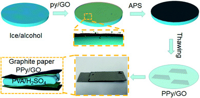
The solid-state symmetric flexible supercapacitors were constructed by sandwich structure. The PVA/H2SO4 gel electrolyte was prepared by adding 6 g PVA powder and 6 g of H2SO4 into 60 mL deionized water. The mixture was then heated at 85 °C under stirring until the solution became clear. Two pieces of PPy/GO free-standing films were adhered to graphite papers to prepare flexible electrodes using conductive silver paste. Finally, a flexible solid-state supercapacitor was successfully assembled and dried at room temperature for 6 h. The size of PPy/GO film electrode used in the cell was 2 cm × 1 cm, and its weight was about 3 mg. The preparation process of PPy/GO flexible supercapacitor was shown in Fig. 1. To facilitate the discussion, the flexible symmetrical supercapacitors made of PPy, PPyGO-1.0, PPy/GO-1.5, PPy/GO-2.0, PPy/GO-2.5 were named as FSC-1, FSC-2, FSC-3, FSC-4, FSC-5.2.5 Characterization
The Fourier transform infrared (FTIR) spectra of PPy/GO films were recorded on a Bruker Vertex 70 spectrometer while using KBr pellets. The scanning electron microscopy (SEM) images of PPy/GO films were collected by a Zeiss Sigma FE-SEM. Water contact angles on PPy/GO films were obtained by using a SDC-100 drop shape analyzer. The cyclic voltammetry (CV), galvanostatic charge/discharge, and electrochemical impedance spectroscopy (EIS) carried out using a CHI 660E electrochemical workstation. EIS was measured with a frequency range from 0.01 Hz to 100 kHz, by using an AC signal of 5 mV amplitude. The area capacitances (Ca, mF cm−2), energy density (Ea, mW h cm−2), and power density (Pa, mW cm−2) of FSC devices were calculated according to the following equations32,33
 | (1) |
 | (2) |
 | (3) |
3 Result and discussion
In this study, a low temperature chemical oxidation polymerization approach was used to prepare self-standing PPy films inside the ice. Firstly, a smooth ice surface was fabricated by the addition with ethanol to decrease the surface energy (Fig. 2i). The pyrrole/GO dispersion was then added on the ice surface. As the temperature decreased, a uniform ice layer containing pyrrole/GO was formed through hydrogen bonding with ice layer (Fig. 2ii). With the addition of oxidant solution, the oxidant and dopant molecules were adsorbed in the monomer ice layer by hydrogen bonding and electrostatic interaction. As the upper solution froze, polymerization was confined between the ice sheets to form two-dimensional film (Fig. 2iii). | ||
| Fig. 2 Schematic illustration of self-standing PPy/GO film: (i) smooth ice, (ii) pyrrole/GO layer, (iii) PPy/GO layer. | ||
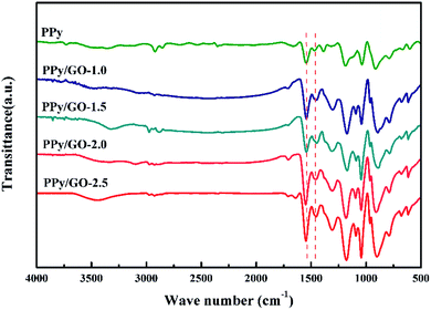
Fig. 3 shows the FTIR spectra of the PPy and PPy/GO-1.0, PPy/GO-1.5, PPy/GO-2.0, PPy/GO-2.5 samples. The characteristic peaks located at 1466 and 1544 cm−1 were assigned to the symmetric and asymmetric ring-stretching modes of pyrrole, respectively.34 The C–H in-plane bending and out-of-plane bending were observed at 1182 and 912 cm−1.16 The peaks at 1300 and 1386 cm−1 were due to the C–C and C–N stretching vibrations, respectively.35 Obviously, with the addition of GO, the C–N stretching vibrations peak was downshifted to 1377 cm−1 probably because of the π–π interactions and hydrogen bonding between the GO layers and aromatic PPy rings.36,37 Additionally, the ratio between the peak area of the symmetric ring stretching mode and asymmetric ring stretching mode (I1466/I1544) could be used to calculate the conjugation length.35,38 The ratio was increasing from 0.583 to 0.681, 0.719, 0.815, 0.969 for PPy, PPy/GO-1.0, PPy/GO-1.5, PPy/GO-2.0, PPy/GO-2.5, respectively, which suggested that the conjugation length increased with further addition of GO. The reason might be that the strong interfacial interaction between PPy and GO induced more electrons delocalized either in the pyrrole units or the benzene ring units of GO.35,39
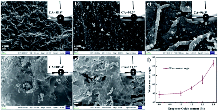
Fig. 4 shows the SEM images of PPy and PPy/GO films. From Fig. 4a, the neat PPy film displayed a smooth morphology, but there were some holes in it, probably due to the penetration of pyrrole monomers in the pores of ice. With the addition of GO, the film became denser, and a few particles appeared on the surface (Fig. 4b). If the content of GO increased, the lamellar structure of GO could be observed (Fig. 4c). Meanwhile, at the higher content, the individual GO sheets attached to PPy could be obviously found (Fig. 4d and e). These results suggested that GO played an important role in the morphology of the films. On the one hand, the nanosheet structure of GO and its strong interaction with pyrrole led to more pyrrole on the surface, thus promoting polymerization.40 On the other hand, the lamellar characteristics of GO and its strong hydrogen bond with the ice layer could effectively prevent pyrrole molecules from infiltrating ice layer. The measurement of water contact angles was performed to investigate the roughness of material surface, as shown in Fig. 4f and insets of Fig. 4a–e. The water contact angle of the composite film increased gradually with the increase of GO content, indicating the increase in the surface roughness of the film. As mentioned above, more PPy particles formed on the surface, thus the surface roughness increased.
Fig. 5 exhibits the CV curves of FSCs devices at different scan rates. The CV curve is closer to the rectangle and more symmetrical, indicating better capacitance performance of the material.41 In Fig. 5a–e, the quasi-rectangular shape appeared in all as-prepared supercapacitor at low scan rates, which confirmed that the PPy and PPy/GO nanocomposite self-supporting films displayed good ionic and electronic transport. At the same time, as the scan rate increased, the highly distorted leaf-shaped CV curves were observed, indicating deviation from the ideal capacitance response, which was consistent with the characteristics of conductive polymer-based supercapacitors.3 With the increase of GO content, the area of CV curves of PPy/GO supercapacitors increased in comparation with the PPy supercapacitor, suggesting the enhancement in capacitance.
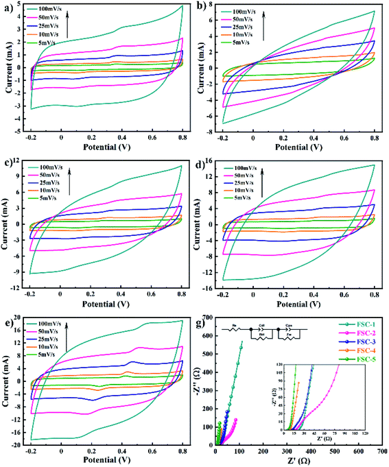 | ||
| Fig. 5 The CV behaviors of solid-state supercapacitors (a) FSC-1, (b) FSC-2, (c) FSC-3, (d) FSC-4, (e) FSC-5 at different scan rates. (g) Nyquist plots of the FSCs devices. | ||
The EIS method is a powerful method to understand the whole electrochemical environment for a meaningful analysis.42 As shown in Fig. 5g, the Nyquist plots of FSCs consisted of a semicircle in the high frequency region and a straight line in the low frequency region. The former semicircle diameter represented the interfacial charge transfer resistance, while the slope of the latter straight line indicated the capacitive property.43,44 The semicircle diameter of FSC-4 was smallest in the high frequency region, indicating the easier electron transfer in the PPy/GO-2.5 film. The inset of Fig. 5g shows the equivalent electrical circuit, where Re is equivalent series resistance (ESR), Rct is the charge transfer resistance, Zw is the Warburg element, Cdl and Cps are the constant phase element (the double layer capacitance and pseudocapacitance), respectively. The PPy showed a comparatively high ESR of 22.4 Ω, whereas the PPy/GO-1.0, PPy/GO-1.0-1.5, PPy/GO-2.0, and PPy/GO-2.5 nanocomposites film exhibited the ESR of 15.23 Ω, 11.11 Ω, 8.84 Ω, and 4.12 Ω. The low ESR of PPy/GO suggested an enhancement of electrical conductivity on the incorporation of GO, which might be attributed to the following reasons. On the one hand, perhaps GO could be partial reduction during in situ polymerization to improve conductivity.45 On the other hand, the conjugation length of PPy could be increasing under the influence of GO, resulting in conducting particle delocalization more easily.35 The improved electrical conductivity facilitated rapid charge transport at the interface, leading to better energy storage behaviors.8,44 Moreover, the straight line in the frequency region was closer to Y axis for PPy/GO supercapacitors, signifying ideal supercapacitor performance due to the synergistic effect of PPy/GO, which was consistent with the results of CV curves.
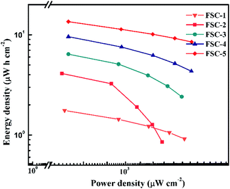
For quantitative evaluation of charge storage capacity, we investigated the GCD performance of FSCs supercapacitors at different current densities, as shown in Fig. 6. The GCD curves of FSCs supercapacitor were almost symmetrical, indicating their good capacitance behaviors. Meanwhile, as the current density increased, the capacitance of all FSCs samples decreased, which was also in agreement with results of CV measurements. It was worth noting that the IR drop of FSC-5 was minimal, confirming its low internal resistance and less energy loss during charge/discharge process.33 Fig. 6f shows the calculated areal specific capacitances of FSCs at different current densities according to the GCD profile. A highest area specific capacitance of 97.3 mF cm−2 was obtained at 1 mA cm−2 for FSC-5 supercapacitor. The other samples introduced with GO, FSC-2 (34.6 mF cm−2), FSC-3 (46.1 mF cm−2) FSC-4 (68.9 mF cm−2) also exhibited higher area specific capacitance than FSC-1 (13.89 mF cm−2). The Ragone plots are shown in Fig. 7. The calculated energy densities according to eqn (2) were 1.8, 4.1, 6.4, 9.6 and 13.56 μW h cm−2 at a power density of 0.5 mW cm−2 for FSC-1, FSC-2, FSC-3, FSC-4, and FSC-5, respectively. The higher content of GO, the better energy storage performance. The GO nanosheets with high surface area not only improved the film forming performance, but also effectively enhanced the conjugation length of PPy, resulting in decrease of resistance of electrode material and increase of charge transport capacity.8,43,46,47
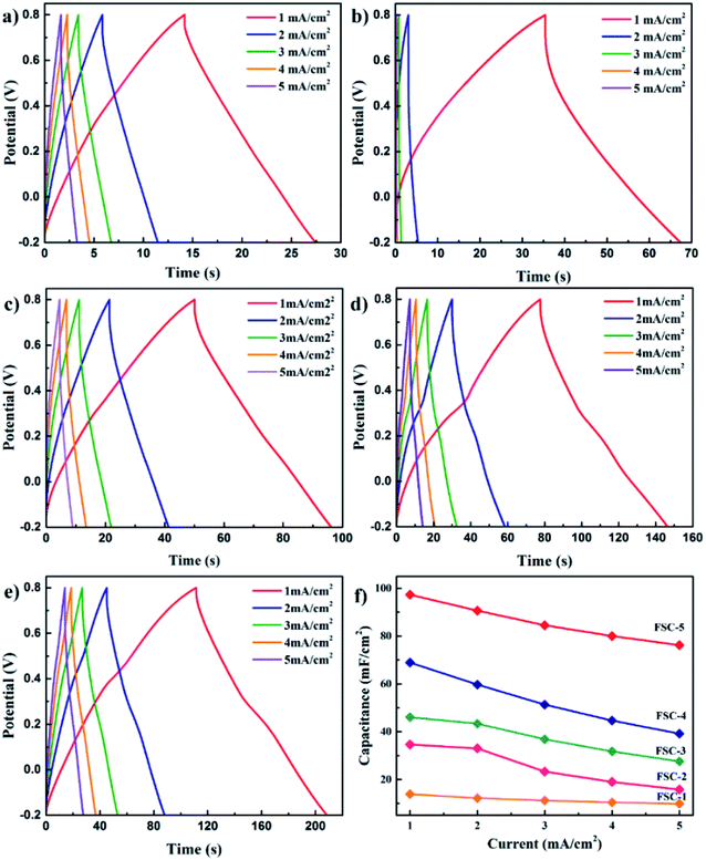 | ||
| Fig. 6 GCD profiles of (a) FSC-1, (b) FSC-2, (c) FSC-3, (d) FSC-4, and (e) FSC-5 at different current densities. (f) The plots of areal specific capacitance for FSCs. | ||
The cycle life was also an important indicator for evaluating supercapacitor performance. Fig. 8a illustrates the cycle life of the FSC-1 and FSC-5 supercapacitors at a current density of 1 mA cm−2. It could be observed that the capacitance of FSC-1 decreased rapidly, while the FSC-5 remained a stable capacitance after 1000 charge/discharge cycles. The areal specific capacitance of FSC-5 dropped only 6%, whereas the FSC-1 lost 55% of capacitance. The volumetric swelling and contraction of the PPy chain during the doping/dedoping (charge/discharge) process significantly influenced the charge distribution and conformation of π conjugated polymer chains, leading to a decline in charge storage capacity. For PPy/GO film, the good electrochemical stability and mechanical strength of GO as the “skeleton” in the composite film could reduce the volume change of PPy chains, thus delaying the degradation of PPy chain and the attenuation of the capacitance.7,23 It was well known that ideal supercapacitors should be adapt to any operating conditions. Therefore, it was of great significance to investigate the electrochemical properties of supercapacitors under bending conditions. Fig. 8b shows the GCD diagrams of the FSC-5 capacitor at different bending angles. The GCD curves with little variation at different bending angles indicated that the prepared FSC-5 possessed the characteristics of flexibility and portability.
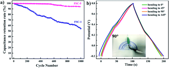 | ||
| Fig. 8 (a) Cycling behaviors of FSC-1 and FSC-5 symmetric supercapacitor. (b) GCD curves of FSC-5 with different bending angles at a current density of 1 mA cm−2. | ||
4 Conclusion
Herein, a simple and easy-to-operate confined polymerization method was performed to fabricate self-standing PPy/GO nanocomposite films. The symmetric flexible supercapacitors were also successfully assembled. The PPy/GO supercapacitor exhibited a higher capacitance of 98.4 mF cm−2 at a current density of 1 mA cm−2 in comparison with that of pure PPy supercapacitor. The capacitance of PPy/GO could still be retained 94.1% after 1000 charge/discharge cycles, indicating its superior cycling stability. The addition of GO improved the film forming performance and increased the conjugation length of PPy, leading to the decrease in the resistance of the materials and enhancement of energy storage property.Conflicts of interest
There are no conflicts to declare.Acknowledgements
This study was supported by the National Natural Science Foundation of China (Contract No. 51963010, 21867011, 21704036 and 21905121). We also thank Jiangxi Key Laboratory of Surface Engineering for SEM characterization.References
- Poonam, K. Sharma, A. Arora and S. K. Tripathi, J. Energy Storage, 2019, 21, 801–825 CrossRef
.
- S. Chen, R. Ramachandran, V. Mani and R. Saraswathi, Int. J. Electrochem. Sci., 2014, 9, 13 Search PubMed
.
- G. A. Snook, P. Kao and A. S. Best, J. Power Sources, 2011, 196, 1–12 CrossRef CAS
.
- R. Raccichini, A. Varzi, S. Passerini and B. Scrosati, Nat. Mater., 2015, 14, 271–279 CrossRef CAS
.
- S. Sollami Delekta, A. D. Smith, J. Li and M. Ostling, Nanoscale, 2017, 9, 6998–7005 RSC
.
- W. Wang, Q. Hao, W. Lei, X. Xia and X. Wang, J. Power Sources, 2014, 269, 250–259 CrossRef CAS
.
- X. Lu, H. Dou, S. Yang, L. Hao, L. Zhang, L. Shen, F. Zhang and X. Zhang, Electrochim. Acta, 2011, 56, 9224–9232 CrossRef CAS
.
- R. Hu, J. Zhao, G. Zhu and J. Zheng, Electrochim. Acta, 2018, 261, 151–159 CrossRef CAS
.
- X. Tang, H. Li, Z. Du, W. Wang and H. Y. Ng, RSC Adv., 2015, 5, 50968–50974 RSC
.
- M. Barakzehi, M. Montazer, F. Sharif, T. Norby and A. Chatzitakis, Electrochim. Acta, 2019, 305, 187–196 CrossRef CAS
.
- P. Sen and A. De, Electrochim. Acta, 2010, 55, 4677–4684 CrossRef CAS
.
- Y. Li, M. Zhou, Y. Wang, Q. Pan, Q. Gong, Z. Xia and Y. Li, Carbon, 2019, 147, 519–531 CrossRef CAS
.
- M. Fu, Z. Qiu, W. Chen, Y. Lin, H. Xin, B. Yang, H. Fan, C. Zhu and J. Xu, Electrochim. Acta, 2017, 248, 292–298 CrossRef CAS
.
- H. Liu, W. Zhu, D. Long, J. Zhu and G. Pezzotti, Appl. Surf. Sci., 2019, 478, 383–392 CrossRef CAS
.
- J.-G. Wang, Y. Yang, Z.-h. Huang and F. Kang, Electrochim. Acta, 2014, 130, 642–649 CrossRef CAS
.
- Y. Shi, L. Pan, B. Liu, Y. Wang, Y. Cui, Z. Bao and G. Yu, J. Mater. Chem. A, 2014, 2, 6086–6091 RSC
.
- P. Bober, Z. Capáková, U. Acharya, B. A. Zasońska, P. Humpolíček, J. Hodan, J. Hromádková and J. Stejskal, Synth. Met., 2019, 252, 122–126 CrossRef CAS
.
- L. Yang, G. Yi, Y. Hou, H. Cheng, X. Luo, S. G. Pavlostathis, S. Luo and A. Wang, Biosens. Bioelectron., 2019, 141, 111444 CrossRef CAS
.
- F. Wang, Z. Liu, X. Wang, X. Yuan, X. Wu, Y. Zhu, L. Fu and Y. Wu, J. Mater. Chem. A, 2016, 4, 5115–5123 RSC
.
- F. Yu, T. Huang, P. Zhang, Y. Tao, F.-Z. Cui, Q. Xie, S. Yao and F. Wang, Energy Storage Mater., 2019, 22, 235–255 CrossRef
.
- X. Zhang, Y. Xia, H. Dou, X. Hao, Y. Wang, B. Ding, S. Dong and J. Wang, Natl. Sci. Rev., 2017, 4, 71–90 CrossRef
.
- S. Stankovich, D. A. Dikin, G. H. B. Dommett, K. M. Kohlhaas, E. J. Zimney, E. A. Stach, R. D. Piner, S. T. Nguyen and R. S. Ruoff, Nature, 2006, 442, 282–286 CrossRef CAS
.
- S. Biswas and L. T. Drzal, Chem. Mater., 2010, 22, 5667–5671 CrossRef CAS
.
- K. Shu, Y. Chao, S. Chou, C. Wang, T. Zheng, S. Gambhir and G. G. Wallace, ACS Appl. Mater. Interfaces, 2018, 10, 22031–22041 CrossRef CAS
.
- S. Konwer, R. Boruah and S. K. Dolui, J. Electron. Mater., 2011, 40, 2248–2255 CrossRef CAS
.
- Z. Lv, Y. Chen, H. Wei, F. Li, Y. Hu, C. Wei and C. Feng, Electrochim. Acta, 2013, 111, 366–373 CrossRef CAS
.
- Y. Yang, D. Wang, Y. Wu, X. Tian, H. Qin, L. Hu, T. Zhang, W. Ni and J. Jin, Macromol. Rapid Commun., 2016, 37, 590–596 CrossRef CAS
.
- J. Chen, Y. Wang, J. Cao, Y. Liu, Y. Zhou, J. H. Ouyang and D. Jia, ACS Appl. Mater. Interfaces, 2017, 9, 19831–19842 CrossRef CAS
.
- A. Davies, P. Audette, B. Farrow, F. Hassan, Z. Chen, J.-Y. Choi and A. Yu, J. Mater. Chem. C, 2011, 115, 17612–17620 CAS
.
- Q. Hao, H. Wang, X. Yang, L. Lu and X. Wang, Nano Res., 2010, 4, 323–333 CrossRef
.
- W. S. Hummers and R. E. Offeman, J. Am. Chem. Soc., 1958, 80, 1339 CrossRef CAS
.
- N. Wang, G. Han, Y. Xiao, Y. Li, H. Song and Y. Zhang, Electrochim. Acta, 2018, 270, 490–500 CrossRef CAS
.
- W. Zhou, G. Han, Y. Xiao, Y. Chang, W. Yuan, Y. Li, C. Liu and Y. Zhang, Electrochim. Acta, 2015, 176, 594–603 CrossRef CAS
.
- C. Wang, Y. Ding, Y. Yuan, A. Cao, X. He, Q. Peng and Y. Li, Small, 2016, 12, 4070–4076 CrossRef CAS
.
- J. Zhong, S. Gao, G. Xue and B. Wang, Macromolecules, 2015, 48, 1592–1597 CrossRef CAS
.
- Y. Ding, J. Zhong, P. Xie, J. Rong, H. Zhu, W. Zheng, J. Wang, F. Gao, L. Shen, H. He and Z. Cheng, Polymers, 2019, 11, 1998 CrossRef CAS
.
- D. Zhang, X. Zhang, Y. Chen, P. Yu, C. Wang and Y. Ma, J. Power Sources, 2011, 196, 5990–5996 CrossRef CAS
.
- V. P. Menon, J. Lei and C. R. Martin, Chem. Mater., 1996, 8, 2382–2390 CrossRef CAS
.
- B. S. Singu and K. R. Yoon, Electrochim. Acta, 2018, 268, 304–315 CrossRef CAS
.
- G. Gnana kumar, C. J. Kirubaharan, S. Udhayakumar, K. Ramachandran, C. Karthikeyan, R. Renganathan and K. S. Nahm, ACS Sustainable Chem. Eng., 2014, 2, 2283–2290 CrossRef CAS
.
- L. Ma, R. Liu, H. Niu, M. Zhao and Y. Huang, Compos. Sci. Technol., 2016, 137, 87–93 CrossRef CAS
.
- W. Choi, H.-C. Shin, J. M. Kim, J.-Y. Choi and W.-S. Yoon, J. Electrochem. Sci. Technol., 2020, 11, 1–13 CrossRef CAS
.
- H.-H. Chang, C.-K. Chang, Y.-C. Tsai and C.-S. Liao, Carbon, 2012, 50, 2331–2336 CrossRef CAS
.
- S. Dhibar, A. Roy and S. Malik, Eur. Polym. J., 2019, 120, 109203 CrossRef CAS
.
- M. Kim, C. Lee, Y. D. Seo, S. Cho, J. Kim, G. Lee, Y. K. Kim and J. Jang, Chem. Mater., 2015, 27, 6238–6248 CrossRef CAS
.
- L. L. Zhang, S. Zhao, X. N. Tian and X. S. Zhao, Langmuir, 2010, 26, 17624–17628 CrossRef CAS
.
- Z. Fan, J. Zhu, X. Sun, Z. Cheng, Y. Liu and Y. Wang, ACS Appl. Mater. Interfaces, 2017, 9, 21763–21772 CrossRef CAS
.
Footnote |
| † Jia Wen and Yang Ding contributed equally to this work. |
| This journal is © The Royal Society of Chemistry 2020 |

