 Open Access Article
Injectable microfluidic hydrogel microspheres based on chitosan and poly(ethylene glycol) diacrylate (PEGDA) as chondrocyte carriers†
Lin Lin‡
 ac,
Yanfang Wang‡
 a,
Ling Wang
 d,
Jianying Panc,
Yichao Xua,
Shiyu Lia,
Da Huanga,
Jiali Chena,
Zilu Liangc,
Panjing Yinc,
Yanbin Lia,
Hongwu Zhanga,
Yaobin Wu
 *a,
Chun Zeng*c and
Wenhua Huang*abc
aGuangdong Engineering Research Center for Translation of Medical 3D Printing Application, Guangdong Provincial Key Laboratory of Medical Biomechanics, Department of Human Anatomy, School of Basic Medical Sciences, Southern Medical University, Guangzhou, China. E-mail: huangwenhua2009@139.com; wuyaobin2018@smu.edu.cn; Fax: +86-020-61648524; Tel: +86-020-61648086
bGuangdong Medical Innovation Platform for Translation of 3D Printing Application, The Third Affiliated Hospital of Southern Medical University, Southern Medical University, Guangzhou, China
cDepartment of Joint Surgery, The Third Affiliated Hospital, Southern Medical University, Guangzhou 510630, PR China. E-mail: zengdavid@126.com
dBiomaterials Research Center, School of Biomedical Engineering, Southern Medical University, Guangzhou 510515, PR China
First published on 29th October 2020
Abstract
Direct injection of chondrocytes in a minimally invasive way has been regarded as the significantly potential treatment for cartilage repair due to their ability to fill various irregular chondral defects. However, the low cell retention and survival after injection still limited their application in clinical transformation. Herein, we present chondrocyte-laden microspheres as cell carriers based on a double-network hydrogel by the combination of the chitosan and poly(ethylene glycol) diacrylate (PEGDA). The microfluidic technique was applied to prepare size-controllable chitosan/PEGDA hydrogel microspheres (CP-MSs) via the water-in-oil approach after photo-crosslinking and physical-crosslinking. The chondrocytes were laden on CP-MSs, which showed good cell viability and proliferation after long-term cell cultivation. The in vitro investigation further demonstrated that chondrocyte-laden CP-MSs were injectable and the cell viability was still high after injection. In particular, these cell-laden microspheres were self-assembled into a 3D cartilage-like scaffold by a bottom-up strategy based on cell–cell interconnectivity, which suggested that these injectable chondrocyte-laden microspheres showed potential applications as chondrocyte carriers for bottom-to-up cartilage tissue engineering.
1. Introduction
In case of the chondral defect caused by acute trauma, reduplicative mechanical abrasion or retrogressive diseases, the restoration and reconstruction of cartilage defects are difficult due to its avascular nature and limited regeneration ability.1,2 Numerous advanced therapeutical methods such as gene therapy and tissue engineering have been investigated in the past decade for cartilage regeneration.3 Among these techniques, direct injection of chondrocytes with minimized surgical invasiveness has also become a promising clinical treatment strategy for the repair and reconstruction of various irregular cartilage defects.4 However, the poor retention of directly injected cells remains a limitation for successful clinical transformation.5 In particular, poor cell retention probably arises from the serious mechanical shear stress suffered by the cell, which destroys the cell membrane during the injection.6,7 In addition, this may be due to the absence of suitable cellular carrier vehicles of 3D structure to improve the viability, diffusion, and proliferation of the injected cells and fill the bulky irregular defects.8–10 The in situ tissue engineering strategy purposes to develop a biomaterial as a cell carrier for the treatment of diseased or damaged tissues to regulate cellular behavior and reconstruct defect tissues.11–13 However, developing suitable biomaterial scaffolds mimicking the microenvironment of chondrocytes remains an on-going challenge for the cartilage tissue engineering applications.Hydrogels have been widely used in various biomedical applications, which show high water contents, pliability, and tissue-like 3D environment.14,15 However, traditional hydrogel bulk scaffolds were difficult to apply for tissue engineering in situ via a minimally invasive way due to their top-down strategy. Furthermore, developing injectable hydrogel scaffolds that can mimic the microenvironment of cartilage for enhancing chondrocyte aggregation and proliferation remains challenging.16–19 Contrastively, utilizing cell-laden micrometer-scale hydrogel microspheres as biobricks has been paid more and more attention,20–24 which showed numerous attractive advantages compared with the conventional 3D bulk hydrogel scaffolds. In addition, such hydrogel microspheres as cell carriers were able to self-assemble into 3D scaffolds based on the bottom-to-up approach.21 The traditional emulsion chemical crosslinking method for solidifying microspheres has a deficiency of agglomeration and nonuniform size.25,26 Contrastively, the microfluidic technique has become an innovative and efficient approach to develop hydrogel microspheres with monodisperse size due to the convenient and controllable micrometer-scale droplet generation process.27–30 The microspheres showed injectability filling the irregular defects, which were able to accelerate nutrient and metabolite exchange by cellular interactions and hence maintain the viability of laden cells.31–34 Therefore, the biomimetic hydrogel microspheres that possessed biocompatibility and size-controllability would be beneficial as chondrocyte carriers for cartilage tissue engineering.
For developing microspheres based on hydrogel biomaterials, various kinds of hydrogel have been investigated during the last decade.35,36 In particular, chitosan is widely acknowledged due to the biocompatibility, biodegradability, and the bioactivity to improve chondrogenesis.37,38 Nevertheless, it also exhibits shortcomings of poor hydrophilicity and poor mechanical properties hindering the production of chitosan microspheres with stable structures and controlled sizes.39,40 Contrastively, poly(ethylene glycol) diacrylate (PEGDA) was a synthetic hydrogel polymer with good biocompatibility and stable mechanical properties,41–44 which facilitates gelation after photo-crosslinking under UV irradiation in the presence of a photo-initiator.45,46 Furthermore, the PEGDA with controllable mechanical properties is also structurally similar to natural tissue for in vivo applications, which indicates the application of PEGDA hydrogels as promising biomimetic materials.47–49 Therefore, we supposed that the combination of chitosan and PEGDA to prepare a double-network hydrogel would not only show the ability to enhance chondrogenesis due to the bioactivity of chitosan but also improve the mechanical stability due to the photo-crosslinking of PEGDA,41,50 which would be a favorable candidate material for microfluidic hydrogel microsphere fabrication.
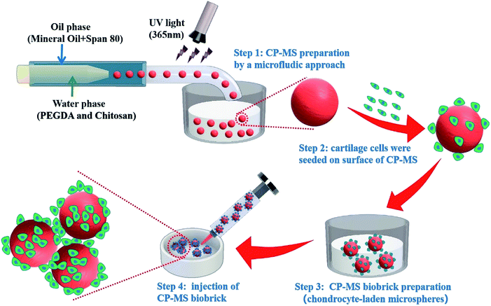
Herein, we present injectable chondrocyte-laden microspheres based on a double-network hydrogel with the combination of chitosan and PEGDA, which are able to self-assemble for the cartilage TE scaffold via a bottom-to-up strategy (Scheme 1). The chitosan/PEGDA (CP) double-network hydrogel was prepared after photo-crosslinking and physical-crosslinking, respectively, and the chemical properties and rheological properties of these CP double-network hydrogels were both investigated. Furthermore, a list of uniform CP-MSs with different sizes were prepared by using a core–shell microfluidic chip. Chondrocytes were seeded on these CP-MSs for the long-term cultivation, and the cell viability and proliferation of chondrocytes were further investigated. In particular, the injectability and self-assembly properties of these cell-laden hydrogel microspheres were also demonstrated. Therefore, these results indicated that these injectable chondrocyte-laden microspheres based on CP double-network hydrogel showed promising potential as chondrocyte carriers for cartilage tissue engineering applications using a bottom-to-up strategy.
2. Materials and methods
2.1 Materials
Poly(ethylene glycol) diacrylate (PEGDA, Mn = 700), chitosan (with a medium viscosity of 200–400 mPa s, analytical grade, 99% pure), acetic acid (anhydrous, ≥99.9%), Span-80 (analytical grade, 99% pure), mineral oil (anhydrous, ≥99.9%), sodium hydroxide powder (NaOH, analytical grade, 99% pure), 2-hydroxy-4′-(2-hydroxyethoxy)-2-methylpropiophenone (Irgacure 2959), nile red, and fluorescein isothiocyanate (FITC) were all purchased from Sigma-Aldrich.2.2 Preparation and characterization of chitosan/PEGDA (CP) hydrogel
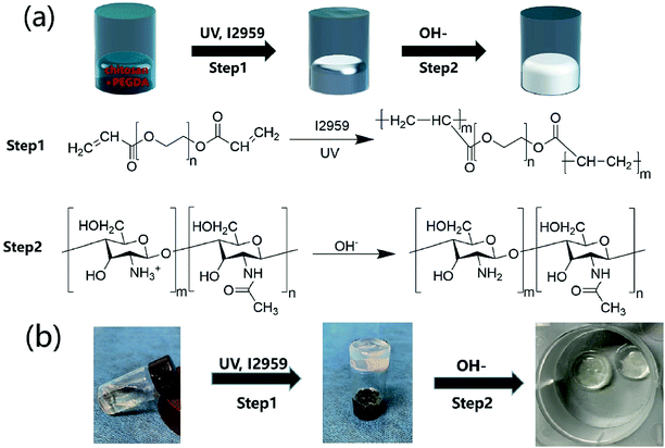
The CP polymer solution was prepared by mixing a PEGDA solution and a chitosan solution (acetic acid as the solvent), and the final concentration of PEGDA and chitosan solutions was 5% w/v and 1% w/v, respectively. The CP double-network hydrogel was synthesized in the following two steps (Fig. 1a): in the first step, the CP polymer solution was photo-crosslinked under UV irradiation at 365 nm for 1 min with Irgacure 2959 (0.05% w/v) as the photo-initiator. In the second step, the photo-crosslinked CP hydrogels were immersed in 0.3 M NaOH solution for 30 s for the physical gelation of chitosan. The formed CP double-network hydrogel was washed 2 times with deionized water before analysis. The rheological properties of these CP hydrogels were evaluated using an HR-2 Hybrid Rheometer (TA Instruments) with a parallel-plate configuration (plate diameter of 20 mm). The measurement was performed using a dynamic frequency sweep test, which covered a range of frequencies from 0.1 to 10 rad s−1 at a shear amplitude of 1%. The strain used was within the linear viscoelastic region, as determined by dynamic amplitude sweep experiments for the CP hydrogel samples (0.1% up to 10% shear amplitude at a frequency of 6.28 rad s−1). The PEGDA hydrogel, chitosan, and CP double-network hydrogel were lyophilized for 2 days, and the Fourier transform infrared (FT-IR) spectra (NICOLET 6700 instrument, Thermo Fisher) of these lyophilized samples were recorded in the wavelength range of 4000–400 cm−1 over 30 scans.2.3 Preparation of microfluidics device
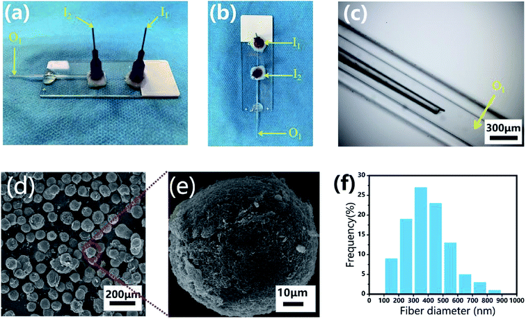
The microfluidic device was fabricated on a glass substrate according to our previous study.51 The coaxial glass microcapillary emulsion device was assembled using a round capillary and a square quartz tube on a glass slide. The capillary microfluidic flow-focusing device was suitable for droplet formation, which was composed of two inlets (I1 and I2) and one outlet (O1) (Fig. 3a–c). The round capillary with an inner diameter of 100 μm (I1 channel) was tapered to the desired orifice using a capillary puller (Sutter Instrument, P-97) and adjusted using a microforge for the channel. The diameter of the desired orifice of the round capillary was approximately 70–90 μm (Fig. 3c). The inner dimension of the square quartz tube (I2 channel) was 500 μm. Then, two 21 G blunt needles (520 μm internal diameter) were inserted into the two inlets respectively, and a silicone tube was connected to the outlet of the final collection channel (O1 channel). Epoxy resin glue was used to seal the tubes where required. The hydrogel microspheres formed in the silicone collection tube were collected using a 50 mL centrifuge tube.2.4 Fabrication of chitosan/PEGDA microspheres (CP-MSs)
For the preparation of monodisperse spherical CP-MSs with different sizes, a CP polymer solution was applied as the inner water phase and mineral oil with 5% v/v span-80 was set as the outer oil phase. The flow rates for the inner and outer phases were set as 5–15 and 30–360 μL min−1, respectively, and the schematic displays the fabrication process of the microfluidic device (Scheme 1). The water phase and oil phase were entered from the I1 inlet (520 μm internal diameter) and the I2 inlet (520 μm internal diameter), respectively (Fig. 3a and b). The CP polymer droplets (oil phase wrap the water phase) were produced by the inner water phase contacting the outer oil phase from the square quartz tube. Consequently, the droplets departed from the O1 outlet of the square quartz tube and then photo-crosslinked to form hydrogel microspheres under UV irradiation for 30 s at the silicone tube. Finally, the photo-crosslinked microspheres were collected in 0.3 M NaOH solution to form the final composite CP-MSs after further physical-crosslinking. The generated CP-MSs were washed with deionized water for 3 times, and the morphology of microspheres was observed using an inverted fluorescence microscope (BX63, Olympus). To label individual microspheres, the FITC dye was mixed with the CP polymer solution before photo-crosslinking, and the microspheres stained with FITC were observed using an inverted fluorescence microscope (BX63, OLYMPUS). The average diameter of the microspheres was measured and analyzed using the ImageJ software, where at least 20 measurements of the microspheres were taken. The microspheres were dehydrated in gradient alcohol including 30%, 50%, 75%, 95%, and 100% ethanol, respectively. The microspheres were then dried in a critical point dryer after using isoamyl acetate to replace ethanol, and the micro-morphology of these dried microspheres was observed using a scanning electron microscope (SEM, Hitachi S-3000, Tokyo, Japan) after coating with gold for 120 s. The average diameter of fibers of the surface of the microspheres was measured using the ImageJ software, where at least 100 measurements of the fiber diameter were taken.2.5 Isolation and cultivation of chondrocytes
Primary chondrocytes of this experiment were harvested from the knee-joint of one-week-old New Zealand white rabbits under sterile conditions. All protocols involving animals were approved by the institutional ethical committee on animal research at Southern Medical University. Briefly, the cartilage was washed three times with Dulbecco's phosphate-buffered saline (DPBS) supplemented with antibiotics (100 U mL−1 streptomycin and 100 U mL−1 penicillin) and then cut into 1 mm3 pieces. The pieces were digested overnight with 0.1% collagenase type II in Dulbecco's modified Eagle's medium (DMEM) in an incubator containing 5% CO2 at 37 °C. Chondrocytes were filtered through a 100 mm strainer and isolated by centrifugation at 1000 rpm for 5 min and washed twice with DMEM supplemented with 10% fetal bovine serum (FBS) to stop the enzymatic reaction. Following centrifugation, the supernatant was discarded, and the cells were re-suspended in a basal culture medium consisting of DMEM with 10% FBS and antibiotics (100 U mL−1 streptomycin and 100 U mL−1 penicillin). The cells were cultured in T25 cell-culture flasks at a density of 30![[thin space (1/6-em)]](https://www.rsc.org/images/entities/char_2009.gif) 000 cells per cm2 at 37 °C in an incubator containing 5% CO2. Do not move to observation within 24 hours during the cultivation of cells to allow the cells to stick to the wall adequately. The culture medium was replaced with a fresh medium every other day. After the confluence reached 80%, the chondrocytes were detached by trypsin and passaged at 1
000 cells per cm2 at 37 °C in an incubator containing 5% CO2. Do not move to observation within 24 hours during the cultivation of cells to allow the cells to stick to the wall adequately. The culture medium was replaced with a fresh medium every other day. After the confluence reached 80%, the chondrocytes were detached by trypsin and passaged at 1![[thin space (1/6-em)]](https://www.rsc.org/images/entities/char_2009.gif) :
:![[thin space (1/6-em)]](https://www.rsc.org/images/entities/char_2009.gif) 4 dilutions. In this experiment, chondrocytes within 4 generations were chosen.
4 dilutions. In this experiment, chondrocytes within 4 generations were chosen.
2.6 Cell viability, proliferation, and morphology analysis of chondrocytes on CP-MSs
CP-MSs were washed 3 times with deionized water and then sterilized by UV irradiation before further use for cell culture following the previous process.35,51 For seeding chondrocytes on CP-Ms, the chondrocytes within 4 generations were mixed with the microspheres in a ratio of 100![[thin space (1/6-em)]](https://www.rsc.org/images/entities/char_2009.gif) :
:![[thin space (1/6-em)]](https://www.rsc.org/images/entities/char_2009.gif) 1 in a Petri dish for cell adhesion for 1 h. Subsequently, the chondrocyte-laden microspheres were further cultured in a culture medium consisting of DMEM with 10% FBS in an incubator with 5% CO2 at 37 °C. Additionally, the cells at the same density were seeded on TCP (tissue culture polystyrene) as the control group. The culture medium was changed every 2 days. For the live/dead staining of chondrocyte-laden microspheres, the live/dead dye solution (Thermo Fisher) was prepared by adding 0.2 μL of calcein AM and 1 μL of ethidium homodimer into 500 μL of PBS, and the cells were washed two times with DPBS and treated with live/dead dye solution at room temperature for 30 min. The live/dead stained chondrocyte-laden microspheres were observed using a confocal laser scanning microscope (Zeiss LSM 880 with Airyscan) and analyzed using the NIH ImageJ software. The Phalloidin-FITC (Thermo Fisher) staining and DAPI (Thermo Fisher) staining of chondrocyte-laden microspheres were performed according to the manufacturer's instructions. Briefly, after washing 3 times with PBS, the samples were fixed with 3.0–4.0% formaldehyde in PBS at room temperature for 10–30 min, and then the fixed cells were rinsed 2–3 times in PBS. Furthermore, the sample was permeabilized by 0.1% Triton X-100 in PBS for 3–5 min, and blocked by 1% BSA for 45 min. Cells were stained with FITC-labeled phalloidin for 90 min, and the cell nuclei were stained with DAPI. The cell morphologies of chondrocyte-laden microspheres were observed using a confocal laser scanning microscope (Zeiss LSM 880 with Airyscan). The cell elongation was measured by the nucleus aspect ratio (maximum/minimum diameter), in which the length–diameter and width–diameter of the three groups were measured and analyzed using the NIH ImageJ software.
1 in a Petri dish for cell adhesion for 1 h. Subsequently, the chondrocyte-laden microspheres were further cultured in a culture medium consisting of DMEM with 10% FBS in an incubator with 5% CO2 at 37 °C. Additionally, the cells at the same density were seeded on TCP (tissue culture polystyrene) as the control group. The culture medium was changed every 2 days. For the live/dead staining of chondrocyte-laden microspheres, the live/dead dye solution (Thermo Fisher) was prepared by adding 0.2 μL of calcein AM and 1 μL of ethidium homodimer into 500 μL of PBS, and the cells were washed two times with DPBS and treated with live/dead dye solution at room temperature for 30 min. The live/dead stained chondrocyte-laden microspheres were observed using a confocal laser scanning microscope (Zeiss LSM 880 with Airyscan) and analyzed using the NIH ImageJ software. The Phalloidin-FITC (Thermo Fisher) staining and DAPI (Thermo Fisher) staining of chondrocyte-laden microspheres were performed according to the manufacturer's instructions. Briefly, after washing 3 times with PBS, the samples were fixed with 3.0–4.0% formaldehyde in PBS at room temperature for 10–30 min, and then the fixed cells were rinsed 2–3 times in PBS. Furthermore, the sample was permeabilized by 0.1% Triton X-100 in PBS for 3–5 min, and blocked by 1% BSA for 45 min. Cells were stained with FITC-labeled phalloidin for 90 min, and the cell nuclei were stained with DAPI. The cell morphologies of chondrocyte-laden microspheres were observed using a confocal laser scanning microscope (Zeiss LSM 880 with Airyscan). The cell elongation was measured by the nucleus aspect ratio (maximum/minimum diameter), in which the length–diameter and width–diameter of the three groups were measured and analyzed using the NIH ImageJ software.
2.7 Self-assembly of chondrocyte-laden CP-MSs in vitro
A Petri dish mold was assumed as a cartilage defect. After culturing chondrocytes on microspheres for 1 day, the chondrocyte-laden microspheres were injected into the Petri dish mold. The injection process uses a micro-injection pump (injection rate of 5 mL h−1), a syringe (volume of 10 mL), and 21 G blunt needles (internal diameter of 600 μm), which was consistent with the previous studies.21,30,32 After injection, these chondrocyte-laden microspheres were further cultured at 37 °C in the culture medium for 7 days. The qualitative cell viability assay was performed using the aforementioned Live/Dead assay kit. The survival rate of chondrocyte laden on microspheres was measured by fluorescence microscopy and using the NIH ImageJ software.2.8 Statistical analysis
Experiments were run at least three times for each sample, and the results are presented as mean ± standard deviation (SD). One-way ANOVA was used for statistical difference analysis of all experimental data. Statistical significance was set at P < 0.05. Quantitative data were obtained using the ImageJ software and SPSS software.3. Results and discussion
3.1 Preparation and characterization of CP hydrogels
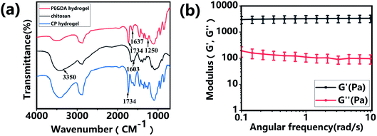
Hydrogels have been widely applied in the field of tissue engineering applications,36,52 and recently injectable hydrogel biomaterials have been paid more attention for developing as cell carriers due to their ability to easily encapsulate or load cells within a 3D environment.23,31 In this study, a double-network hydrogel was prepared based on the combination of chitosan and PEGDA, because chitosan showed good biocompatibility and nanofibrous structure after lyophilization and PEGDA showed the convenient gelation process via photo-crosslinking. The preparation process of CP hydrogels consisted of two steps, as shown in Fig. 1a. For the first step, the PEGDA photo-crosslinked network of the CP hydrogel was formed after UV irradiation with the Irgacure 2959 photo-initiator. Subsequently, the double-network CP hydrogel was prepared after the physical-crosslinking reaction of chitosan under NaOH solution treatment (Fig. 1b). In the previous study, chitosan microspheres were able to be prepared by the physical-crosslinking process.23,53 Therefore, we supposed that the combination of chitosan and PEGDA to prepare a double-network hydrogel would not only provide the mechanical stability due to the photo-crosslinking of PEGDA but also show the ability to enhance cell adhesion due to physical-crosslinking of chitosan. The combination of chitosan and PEGDA was further analyzed by FTIR measurement. As shown in Fig. 2a, the peaks of –NH at 1603 cm−1 and 3350 cm−1 assigned to chitosan were both observed in CP double network hydrogels, and the peak of –C![[double bond, length as m-dash]](https://www.rsc.org/images/entities/char_e001.gif) O at 1734 cm−1 and the peak of -C-O at 1250 cm−1 were also appeared in CP double network hydrogels compared with the PEGDA hydrogel. Especially, the disappeared double bond (C
O at 1734 cm−1 and the peak of -C-O at 1250 cm−1 were also appeared in CP double network hydrogels compared with the PEGDA hydrogel. Especially, the disappeared double bond (C![[double bond, length as m-dash]](https://www.rsc.org/images/entities/char_e001.gif) C) signals at 1637 cm−1 further confirmed the photo-crosslinking reaction of the PEGDA network. These data suggested the good blending of chitosan and PEGDA and the successful preparation of the CP double-network hydrogel, which is convincing and matches well with the previous study.54 The mechanical property of the CP double network hydrogel was measured by the rheological test. Fig. 2b shows that the storage modulus (G′) was higher than the loss modulus (G′′), and the G′ and G′′ of CP hydrogels exhibited a slight variation and low strain dependencies with frequency ranging from 0.1 to 10 rad s−1, which suggested that the CP hydrogel performed a good and stable crosslinking network. In addition, the values of tan
C) signals at 1637 cm−1 further confirmed the photo-crosslinking reaction of the PEGDA network. These data suggested the good blending of chitosan and PEGDA and the successful preparation of the CP double-network hydrogel, which is convincing and matches well with the previous study.54 The mechanical property of the CP double network hydrogel was measured by the rheological test. Fig. 2b shows that the storage modulus (G′) was higher than the loss modulus (G′′), and the G′ and G′′ of CP hydrogels exhibited a slight variation and low strain dependencies with frequency ranging from 0.1 to 10 rad s−1, which suggested that the CP hydrogel performed a good and stable crosslinking network. In addition, the values of tan![[thin space (1/6-em)]](https://www.rsc.org/images/entities/char_2009.gif) δ (G′/G′′) were located in a narrow range of 0.02–0.07, which indicated that CP hydrogels primarily displayed an elastic behavior with a relative small viscous component. The chitosan hydrogel formed by physical-crosslinking had a higher viscous modulus but a lower elastic modulus, which also suggested that chitosan hydrogel microspheres would serve as the injectable hydrogel microspheres.55 In addition, the PEGDA hydrogel formed by photo-crosslinking had a higher elastic modulus but a lower viscous modulus.56 Therefore, the elastic modulus of composite injectable CP-MSs was able to improve apparently by introducing the PEGDA hydrogel.55 Therefore, according to the combination of chitosan with a higher viscous modulus and PEGDA with a higher elastic modulus, we suggested that these microspheres based on the CP double-network hydrogel showed promising potential as injectable microspheres.
δ (G′/G′′) were located in a narrow range of 0.02–0.07, which indicated that CP hydrogels primarily displayed an elastic behavior with a relative small viscous component. The chitosan hydrogel formed by physical-crosslinking had a higher viscous modulus but a lower elastic modulus, which also suggested that chitosan hydrogel microspheres would serve as the injectable hydrogel microspheres.55 In addition, the PEGDA hydrogel formed by photo-crosslinking had a higher elastic modulus but a lower viscous modulus.56 Therefore, the elastic modulus of composite injectable CP-MSs was able to improve apparently by introducing the PEGDA hydrogel.55 Therefore, according to the combination of chitosan with a higher viscous modulus and PEGDA with a higher elastic modulus, we suggested that these microspheres based on the CP double-network hydrogel showed promising potential as injectable microspheres.
3.2 Fabrication of CP-MSs based on a microfluidic chip
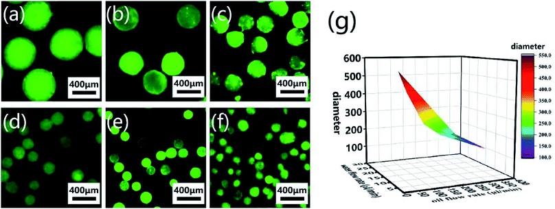
Monodisperse spherical CP-MSs were fabricated using a capillary microfluidic flow-focusing chip, which consisted of two inlets (I1 and I2) and one outlet (O1) (Fig. 3a–c). These microspheres were prepared in the following three stages (Scheme 1). The first stage was the CP solution droplet generation by the interaction of water phase flow and oil phase flow. At the second stage, these monodisperse droplets dispersed within the oil phase were then photo-crosslinked to form hydrogel microspheres under UV irradiation. The last stage was that the CP double-network hydrogel microspheres were formed after the physical-crosslinking of chitosan in the NaOH solution. As shown in Fig. 3d, dried microspheres with spherical morphology were observed in the SEM images. In particular, the surface of these microspheres showed the nanofibrous structure (Fig. 3e), and the average diameter of these nanofibers was 397 ± 146 nm ranging from 300 to 500 nm (Fig. 3f). Previous studies have demonstrated that the nanofibrous microstructure would have a positive effect on cell adhesion.23,57–59 Comparing with the chitosan–siloxane microspheres and Chitin microspheres as described in the previous studies,60,61 in this research these injectable microspheres were prepared by a double-network hydrogel based on the combination of chitosan and PEGDA, which would not only provide the mechanical stability due to the photo-crosslinking of PEGDA but also show the ability to enhance cell adhesion due to physical-crosslinking of chitosan. In particular, many previous studies indicated that microspheres with a nanofibrous surface were able to enhance cell adhesion.23,62,63 Therefore, we suggested that in this study, these CP double-network microspheres with nanofibrous surface would be beneficial for chondrocytes adhesion and proliferation.CP-MSs with different sizes were further prepared via this microfluidic chip by regulating the relative flow rates and flow rate ratio of oil and water phases. To label individual microspheres, FITC was mixed with the CP solution before injection into the microfluidic chip. Fig. 4a–f shows the fluorescence images of a list of uniform spherical CP-MSs with different diameters by tuning the flow rates of the oil and water phases. As shown in Table 1, when the water flow rate was chosen as 10 μL min−1, the diameter of microspheres decreased from 550 ± 9 μm to 121 ± 23 μm with the flow rate ratio (oil flow rate/water flow rate) increasing from 3 to 36. In addition, when keeping the correlative flow rate ratio of 18, the diameter of microspheres decreased from 301 ± 21 μm to 195 ± 8 μm when the water flow rate increased from 5 to 15 μL min−1 and the oil flow rate increased from 90 to 270 μL min−1, respectively. These microspheres with different diameters were named CP-MS-1, CP-MS-2, CP-MS-3, CP-MS-4, CP-MS-5, and CP-MS-6 according to different flow rates and flow rate ratios of oil and water phases (Table 1). Therefore, these results indicated that not only the flow rates of the CP solution and the oil phase but also the flow rate ratio were able to control the size of microspheres (Fig. 4g). In addition, the histograms of the diameter distribution of microspheres in Fig. S2† and the coefficient of variation analysis in Table 1, respectively, demonstrate the dispersity of these microspheres. These results indicated that the coefficient of variation of CP-MS-1, CP-MS-2, CP-MS-3, CP-MS-4, and CP-MS-5 was 1.63%, 4.97%, 6.98%, 7.28%, and 4.10%, respectively, while that of CP-MS-6 was as higher as 19.0% (Fig. 4f). This reason was that when the oil flow rate was set as 360 μL min−1, the oil flow rate was relatively fast, and the emulsification was incomplete immediately between the inner water phase and the outer oil phase. Therefore, the monodisperse CP-MS were successfully generated via the microfluidic technique by regulating the relative flow rates and the flow rate ratio of oil and water phases. Furthermore, for the microspheres without the characteristics of stable structure and controlled sizes, it was not beneficial for chondrocyte adhesion and proliferation on the surface of microspheres. Therefore, CP-MS-1 (550 ± 9 μm) with a relatively large diameter and CP-MS-4 (220 ± 16 μm) with a relatively small diameter were both applied for the subsequent investigation of CP-MSs as chondrocyte carriers.
| Sample code | Water flow rate (μL min−1) | Oil flow rate (μL min−1) | Flow rate ratio (oil/water) | Diameter (μm) | Coefficient of variation (%) |
|---|---|---|---|---|---|
| CP-MS-1 | 10 | 30 | 3 | 550 ± 9 | 1.63 |
| CP-MS-2 | 10 | 60 | 6 | 443 ± 22 | 4.97 |
| CP-MS-3 | 5 | 90 | 18 | 301 ± 21 | 6.98 |
| CP-MS-4 | 10 | 180 | 18 | 220 ± 16 | 7.28 |
| CP-MS-5 | 15 | 270 | 18 | 195 ± 8 | 4.10 |
| CP-MS-6 | 10 | 360 | 36 | 121 ± 23 | 19.00 |
3.3 Cell viability and morphology of chondrocytes on CP-MSs
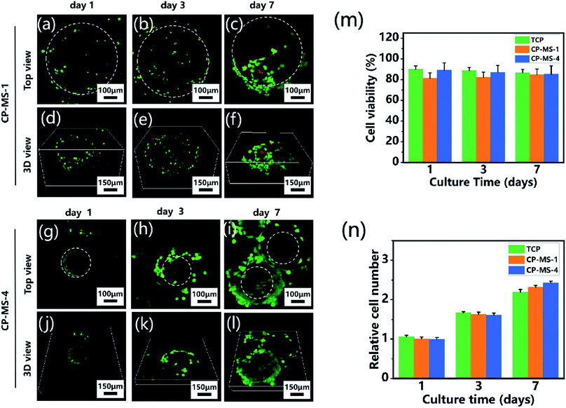
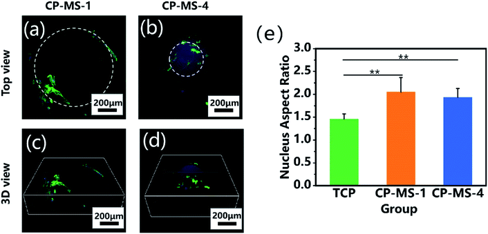
To determine the biocompatibility of CP-MSs for cell adhesion, viability, and proliferation, chondrocytes were seeded and cultured on CP-MSs for 7 days. During the period of cultivation, the cell viability of chondrocyte-laden CP-MS-1 and CP-MS-4 was measured using the live/dead staining. The confocal images showed that most of the chondrocytes were stained with green during the cultivation for 1, 3, and 7 days (Fig. 5a–c and g–i), and the statistical analysis results showed that the cell viability was as higher as 80% in both CP-MS-1 and CP-MS-4 groups even after culturing for 7 days. These data indicated the good cell viability of cell-laden CP-MS as well as the TCP control group, and also illustrated that the cell viability does not decrease with the increase in cultivation time (Fig. 5m). Furthermore, the top view (Fig. 5a–c and g–i) images clearly showed that the chondrocytes on CP-MS-1 and CP-MS-4 not only maintained good vitality but also showed good cell proliferation during the 7 days of cultivation, while there was no statistical significance between the two CP-MS groups and the TCP group at days 1, 3, and 7 (Fig. 5n). In addition, the 3D view (Fig. 5d–f and j–l) images further indicated that the chondrocytes were grown and they fully filled around the 3D surface of these microspheres. These obvious results of the high cell viability and significant proliferation of chondrocytes on microspheres with different diameters further demonstrated that both CP-MSs with a relatively large or small diameter offered the excellent cellular microenvironment for chondrocyte adhesion and proliferation. In particular, compared with the individual chondrocyte-laden CP-MS-1, chondrocyte-laden CP-MS-4 tended to agglomerate together without any other additional stimuli after long-term culture (Fig. 5f and l). The findings suggested that the self-assembly of cell-laden microspheres was observed when chondrocytes proliferated on the surface of microspheres due to the cell–cell interconnectivity between the microspheres with a smaller diameter. Therefore, we supposed that the sizes of the appropriate microspheres would be able to offer a better cellular microenvironment for chondrocyte adhesion and proliferation.The cellular morphologies of chondrocytes on CP-MSs were further investigated by using phalloidin-FITC/DAPI staining. Fig. 6a and b shows that the cells on both CP-MS-1 and CP-MS-4 showed organized actin fibers, which demonstrated a spreading morphology on the surface of these microspheres. Moreover, the 3D view images showed that chondrocytes were gradually spread over the 3D spherical surface of the microspheres (Fig. 6c and d). The cellular elongation properties of cells on the microsphere were measured and analyzed by the nuclear diameter ratio (Fig. S1†). As shown in Fig. 6e, the nucleus aspect ratios of the CP-MS-1 and CP-MS-4 group were significantly higher than that of cells in the TCP group (P < 0.01), which suggested that the 3D nanofibrous microenvironment of CP-MSs was more suitable for the 3D cell elongation than the 2D TCP environment. These results further indicated that these microspheres with a controllable diameter and a nanofibrous surface showed promising potential as the injectable chondrocyte carrier for cartilage tissue engineering applications.
3.4 Injectable self-assembly of chondrocyte-laden microspheres
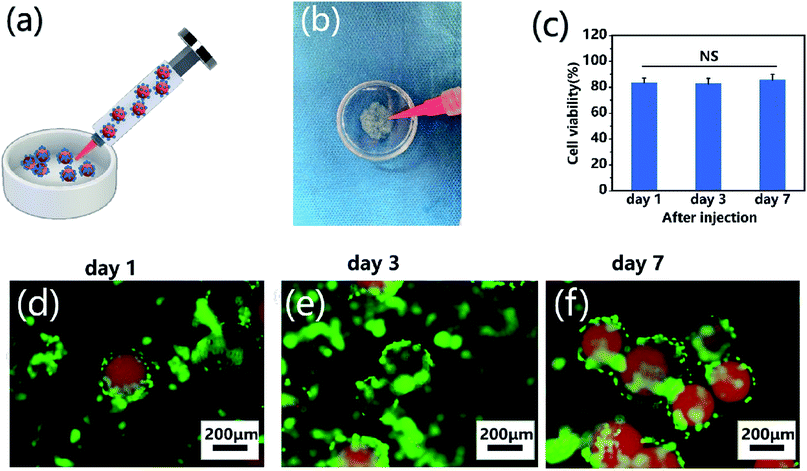
To demonstrate the self-assembly of chondrocyte-laden microspheres after injection, chondrocytes were seeded on CP-MS-4 for culturing 1 day. Subsequently, these cell-laden microspheres were then injected into a Petri dish mold mimicking as the cartilage defect (Fig. 7a and b). We hypothesized that the surface-laden microspheres would reduce the shear stress on cells during the injection process due to the protection of these CP double-network hydrogel microspheres. It is well known that bare cells were subjected to serious mechanical shear stress during the injection process, resulting in a decrease in cell viability or even cell death.5,21,64 For investigating whether the injection process would damage cells on microspheres, cell viability analysis was applied after cell injection and further culturing for 7 days, respectively (Fig. 7c). In the study of Cao and the co-worker, the naked BMSCs die violently with the injection rate and only 35% of BMSCs survive at the injection rate of 5 mL h−1.21 In our study, we also use an injection rate of 5 mL h−1, and these statistical analysis results showed that the cell viability was as high as 80% after injection, and there was no significant decrease in cell viability to be observed even after cultivation for 7 days. These data suggested that the injection process did not show a negative effect on cell viability due to the protection of these CP double-network hydrogel microspheres. Furthermore, the self-assembly of these microspheres after injection was evaluated by fluorescent images, where nile red dye was blended with a CP polymer solution to label single microspheres, and chondrocytes were stained with calcium AM. As shown in Fig. 7d–f, the chondrocyte-laden microspheres underwent the course of bottom-to-up self-assembly after injection during 7 days of cultivation. These results indicated that the individual microspheres started to connect through cell–cell interconnectivity with the prolonged cultivation time, which would ultimately self-assemble into 3D cartilage-like scaffolds. Therefore, we suggested that the injectable chondrocyte-laden microspheres would potentially self-assemble into a 3D cartilage-like scaffold via a bottom-to-up approach.4. Conclusion
In summary, we have successfully developed a list of injectable CP-MSs based on CP double-network hydrogels using a microfluidic chip and further demonstrated their potentials as cell carriers. These CP-MSs with sizes ranging from 121 ± 23 to 550 ± 9 μm were prepared by adjusting the flow rates and flow ratios of the water and oil phases. Chondrocytes were seeded and cultured on these CP-MSs, and the cell culture results indicated good cell biocompatibility of these microspheres. In particular, long-term cultivation results further indicated that these microspheres with nanofibrous surfaces were able to improve cell adhesion and proliferation. The injection and self-assembly properties of these chondrocyte-laden microspheres were also demonstrated, and the cell viability did not show a significant decrease during the injection process. Moreover, the self-assembly of cell-laden microspheres based on cell–cell interconnectivity was observed during 7 days of cultivation. These results indicated that these injectable chondrocyte-laden microspheres showed promising potential applications as chondrocyte carriers for bottom-to-up cartilage tissue engineering applications.Conflicts of interest
There are no conflicts to declare.Acknowledgements
This work was supported by the National Key R&D Program of China (2017YFC1103400), the National Natural Science Foundation of China (31972915 and 31900960), the Science and Technology Project of Guangdong Province (2016B090917001), the Natural Science Foundation of Guangdong Province (2019A1515011413), the Key-Area Research and Development Program of Guangdong Province (2018B090944002), and the Sanming Project of Medicine in Shenzhen (SZSM201612019).References
- L. Danisovic, I. Varga, R. Zamborsky and D. Bohmer, Exp. Biol. Med., 2012, 237, 10–17 CrossRef CAS.
- R. S. Tuan, A. F. Chen and B. A. Klatt, J. Am. Acad. Orthop. Surg., 2013, 21, 303–311 CrossRef.
- N. P. Truong, W. Gu, I. Prasadam, Z. Jia, R. Crawford, Y. Xiao and M. J. Monteiro, Nat. Commun., 2013, 4, 1902 CrossRef.
- S. R. Tew, A. D. Murdoch, R. P. Rauchenberg and T. E. Hardingham, Methods, 2008, 45, 2–9 CrossRef CAS.
- B. A. Aguado, W. Mulyasasmita, J. Su, K. J. Lampe and S. C. Heilshorn, Tissue Eng., Part A, 2012, 18, 806–815 CrossRef CAS.
- H. Outani, M. Okada, A. Yamashita, K. Nakagawa, H. Yoshikawa and N. Tsumaki, PLoS One, 2013, 8, e77365 CrossRef CAS.
- H. K. Kleinman, D. Philp and M. P. Hoffman, Curr. Opin. Biotechnol., 2003, 14, 526–532 CrossRef CAS.
- S. K. Boda, S. Chen, K. Chu, H. J. Kim and J. Xie, ACS Appl. Mater. Interfaces, 2018, 10, 25069–25079 CrossRef CAS.
- H. Chiang, T. F. Kuo, C. C. Tsai, M. C. Lin, B. R. She, Y. Y. Huang, H. S. Lee, C. S. Shieh, M. H. Chen, J. A. Ramshaw, J. A. Werkmeister, R. S. Tuan and C. C. Jiang, J. Orthop. Res., 2005, 23, 584–593 CrossRef.
- R. Levato, J. Visser, J. A. Planell, E. Engel, J. Malda and M. A. Mateos-Timoneda, Biofabrication, 2014, 6, 035020 CrossRef.
- P. X. Ma, Adv. Drug Delivery Rev., 2008, 60, 184–198 CrossRef CAS.
- Y. Yang, X. Song, X. Li, Z. Chen, C. Zhou, Q. Zhou and Y. Chen, Adv. Mater., 2018, 30, e1706539 CrossRef.
- L. Wang, Y. Wu, T. Hu, B. Guo and P. X. Ma, Acta Biomater., 2017, 59, 68–81 CrossRef CAS.
- S. L. Vega, M. Y. Kwon and J. A. Burdick, Eur. Cells Mater., 2017, 33, 59–75 CrossRef CAS.
- U.-J. Kim, J. Park, H. Joo Kim, M. Wada and D. L. Kaplan, Biomaterials, 2005, 26, 2775–2785 CrossRef CAS.
- S. Saxena and L. A. Lyon, J. Colloid Interface Sci., 2015, 455, 93–100 CrossRef CAS.
- T. G. Kim, H. Shin and D. W. Lim, Adv. Funct. Mater., 2012, 22, 2446–2468 CrossRef CAS.
- Z. Liu, Q. Lin, Y. Sun, T. Liu, C. Bao, F. Li and L. Zhu, Adv. Mater., 2014, 26, 3912–3917 CrossRef CAS.
- J. Liu, H. Lin, X. Li, Y. Fan and X. Zhang, RSC Adv., 2015, 5, 54446–54453 RSC.
- D. L. Elbert, Curr. Opin. Biotechnol., 2011, 22, 674–680 CrossRef CAS.
- Q. Feng, Q. Li, H. Wen, J. Chen, M. Liang, H. Huang, D. Lan, H. Dong and X. Cao, Adv. Funct. Mater., 2019, 29, 1906690 CrossRef CAS.
- Y. Hu, M. Grosche, S. Sheshachala, C. Oelschlaeger, N. Willenbacher, K. S. Rabe and C. M. Niemeyer, Angew. Chem., Int. Ed., 2019, 58, 17269–17272 CrossRef CAS.
- Y. Zhou, H. L. Gao, L. L. Shen, Z. Pan, L. B. Mao, T. Wu, J. C. He, D. H. Zou, Z. Y. Zhang and S. H. Yu, Nanoscale, 2016, 8, 309–317 RSC.
- D. J. Caldwell, R. R. Rao and J. P. Stegemann, Adv. Healthcare Mater., 2013, 2, 673–677 CrossRef CAS.
- D. L. Elbert, Acta Biomater., 2011, 7, 31–56 CrossRef CAS.
- S. Dhaliwal, S. Jain, H. P. Singh and A. K. Tiwary, AAPS J., 2008, 10, 322–330 CrossRef CAS.
- E. Y. Liu, S. Jung, D. A. Weitz, H. Yi and C. H. Choi, Lab Chip, 2018, 18, 323–334 RSC.
- Y. Wu, L. Wang, B. Guo and P. X. Ma, J. Mater. Chem. B, 2014, 2, 3674–3685 RSC.
- Q. Li, Y. W. Zhang, C. F. Wang, D. A. Weitz and S. Chen, Adv. Mater., 2018, 30, e1803475 CrossRef.
- C. B. Highley, K. H. Song, A. C. Daly and J. A. Burdick, Adv. Sci., 2019, 6, 1801076 CrossRef.
- X. Zhao, S. Liu, L. Yildirimer, H. Zhao, R. Ding, H. Wang, W. Cui and D. Weitz, Adv. Funct. Mater., 2016, 26, 2809–2819 CrossRef CAS.
- J. E. Mealy, J. J. Chung, H. H. Jeong, D. Issadore, D. Lee, P. Atluri and J. A. Burdick, Adv. Mater., 2018, 30, e1705912 CrossRef.
- C. Cha, J. Oh, K. Kim, Y. Qiu, M. Joh, S. R. Shin, X. Wang, G. Camci-Unal, K. T. Wan, R. Liao and A. Khademhosseini, Biomacromolecules, 2014, 15, 283–290 CrossRef CAS.
- M. N. Vu, H. G. Kelly, A. K. Wheatley, S. Peng, E. H. Pilkington, N. A. Veldhuis, T. P. Davis, S. J. Kent and N. P. Truong, Small, 2020, 16, 2002861 CrossRef CAS.
- B. V. Slaughter, S. S. Khurshid, O. Z. Fisher, A. Khademhosseini and N. A. Peppas, Adv. Mater., 2009, 21, 3307–3329 CrossRef CAS.
- N. A. Peppas, B. V. Slaughter and M. A. Kanzelberger, in Polymer Science: A Comprehensive Reference, 2012, pp. 385–395, DOI:10.1016/b978-0-444-53349-4.00226-0.
- F. Croisier and C. Jérôme, Eur. Polym. J., 2013, 49, 780–792 CrossRef CAS.
- D. J. Griffon, M. R. Sedighi, D. V. Schaeffer, J. A. Eurell and A. L. Johnson, Acta Biomater., 2006, 2, 313–320 CrossRef.
- S. Jung and H. Yi, Langmuir, 2012, 28, 17061–17070 CrossRef CAS.
- I. M. El-Sherbiny, E. M. Abdel-Bary and D. R. K. Harding, J. Appl. Polym. Sci., 2006, 102, 977–985 CrossRef CAS.
- V. B. Morris, S. Nimbalkar, M. Younesi, P. McClellan and O. Akkus, Ann. Biomed. Eng., 2017, 45, 286–296 CrossRef.
- G. Ma, X. Zhang, J. Han, G. Song and J. Nie, Int. J. Biol. Macromol., 2009, 45, 499–503 CrossRef CAS.
- C. Zhong, J. Wu, C. A. Reinhart-King and C. C. Chu, Acta Biomater., 2010, 6, 3908–3918 CrossRef CAS.
- M. B. Browning, S. N. Cereceres, P. T. Luong and E. M. Cosgriff-Hernandez, J. Biomed. Mater. Res., Part A, 2014, 102, 4244–4251 CAS.
- M. K. Schesny, M. Monaghan, A. H. Bindermann, D. Freund, M. Seifert, J. A. Eble, S. Vogel, M. P. Gawaz, S. Hinderer and K. Schenke-Layland, Biomaterials, 2014, 35, 7180–7187 CrossRef CAS.
- C. G. Williams, A. N. Malik, T. K. Kim, P. N. Manson and J. H. Elisseeff, Biomaterials, 2005, 26, 1211–1218 CrossRef CAS.
- S. Sokic and G. Papavasiliou, Tissue Eng., Part A, 2012, 18, 2477–2486 CrossRef CAS.
- W. Zhang, Q. Lian, D. Li, K. Wang, D. Hao, W. Bian and Z. Jin, Mater. Sci. Eng., C, 2015, 46, 10–15 CrossRef CAS.
- C. H. Chen, C. H. Chang, K. C. Wang, C. I. Su, H. T. Liu, C. M. Yu, C. B. Wong, I. C. Wang, S. W. Whu and H. W. Liu, Knee Surg. Sports Traumatol. Arthrosc., 2011, 19, 1597–1607 CrossRef.
- M. V. N. Siddharth, Y. Mousa and A. Ozan, Front. Bioeng. Biotechnol., 2016, 4 DOI:10.3389/conf.FBIOE.2016.01.00514.
- J. Chen, D. Huang, L. Wang, J. Hou, H. Zhang, Y. Li, S. Zhong, Y. Wang, Y. Wu and W. Huang, J. Colloid Interface Sci., 2020, 574, 162–173 CrossRef CAS.
- Y. Wu, L. Wang, T. Hu, P. X. Ma and B. Guo, J. Colloid Interface Sci., 2018, 518, 252–262 CrossRef CAS.
- S. Ladet, L. David and A. Domard, Nature, 2008, 452, 76–79 CrossRef CAS.
- T. Rattanawongwiboon, K. Hemvichian, P. Lertsarawut and P. Suwanmala, Radiat. Phys. Chem., 2020, 170, 108656 CrossRef CAS.
- C. Chen, L. Wang, L. Deng, R. Hu and A. Dong, J. Biomed. Mater. Res., Part A, 2013, 101, 684–693 CrossRef.
- D.-y. Teng, Z.-m. Wu, X.-g. Zhang, Y.-x. Wang, C. Zheng, Z. Wang and C.-x. Li, Polymer, 2010, 51, 639–646 CrossRef CAS.
- Y. Wu, L. Wang, B. Guo and P. X. Ma, ACS Nano, 2017, 11, 5646–5659 CrossRef CAS.
- L. Wang, Y. Wu, T. Hu, P. X. Ma and B. Guo, Acta Biomater., 2019, 96, 175–187 CrossRef CAS.
- L. Wang, Y. Wu, B. Guo and P. X. Ma, ACS Nano, 2015, 9, 9167–9179 CrossRef CAS.
- Y. Shirosaki, M. Nakatsukasa, S. Yasutomi, S. Cruz-Neves, S. Hayakawa, A. Osaka, T. Maeda and T. Miyazaki, Polymers, 2019, 11, 1676–1676 CrossRef CAS.
- B. Duan, X. Zheng, Z. Xia, X. Fan, L. Guo, J. Liu, Y. Wang, Q. Ye and L. Zhang, Angew. Chem., Int. Ed., 2015, 54, 5152–5156 CrossRef CAS.
- X. Liu, X. Jin and P. X. Ma, Nat. Mater., 2011, 10, 398–406 CrossRef CAS.
- Z. Zhang, R. L. Marson, Z. Ge, S. C. Glotzer and P. X. Ma, Adv. Mater., 2015, 27, 3947–3952 CrossRef CAS.
- D. T. Covas, H. Outani, M. Okada, A. Yamashita, K. Nakagawa, H. Yoshikawa and N. Tsumaki, PLoS One, 2013, 8, e77365 CrossRef.
Footnotes |
| † Electronic supplementary information (ESI) available. See DOI: 10.1039/d0ra07318k |
| ‡ These authors contributed equally to this work. |
| This journal is © The Royal Society of Chemistry 2020 |

