
 Open Access Article
 This Open Access Article is licensed under a Creative Commons Attribution-Non Commercial 3.0 Unported Licence
Strong correlation between flux pinning and epitaxial strain in the GdBa2Cu3O7−x/La0.7Sr0.3MnO3 nanocrystalline heterostructure
J. Y. Oha,
C. Y. Songa,
Y. J. Koa,
J. M. Leeb,
W. N. Kangb,
D. S. Yangc and
B. Kang *a
*a
aDepartment of Physics, Chungbuk National University, Cheongju, Korea. E-mail: bwkang@chungbuk.ac.kr; Fax: +82 43 274 7811; Tel: +82 43 261 3394
bDepartment of Physics, Sungkyunkwan University, Suwon, Korea
cDepartment of Physics Education, Chungbuk National University, Cheongju, Korea
First published on 26th October 2020
Abstract
The effect of magnetic flux pinning is investigated in GdBa2Cu3O7 (GdBCO) thin films with two different types of ferromagnetic La0.7Sr0.3MnO3 (LSMO) buffers (nanoparticles and a layer) deposited on an STO substrate. Magnetization analyses reveal the presence of multiple flux pinning mechanisms responsible for the improvement in the critical current density of GdBCO films. While core pinning becomes a dominant pinning mechanism in GdBCO films with LSMO nanoparticles, a hybrid effect of magnetic-volume and core-point pinning is observed in GdBCO films with LSMO layers. Examinations of local structures for both LSMO and GdBCO using extended X-ray absorption fine structure spectroscopy (EXAFS) exhibit a close relation between the parameters in the pinning force scaling and the length ratio of the Mn–O bond to the Cu–O bond. This result implies that the origin of core pinning is probably attributed to epitaxial strain induced by lattice mismatch between LSMO and GdBCO. Therefore, an appropriate strain state of LSMO is required for an effective operation of magnetic pinning.
1. Introduction
For the large-scale application of superconductors, high-Tc superconductors (HTSC) are one of the most promising materials which can transport high electrical currents under magnetic fields without losses at liquid nitrogen temperature (77 K). One of the key issues for the practical applications of HTSC is how to improve the critical current density (Jc), which depends entirely on the interaction between vortices and pinning centers. The motion of vortices is a main mechanism limiting the values of Jc, and one way to prevent the vortex movement is to pin vortices on pinning sites. For this purpose, the search for a suitable process of generating nano-scale defects inside the superconducting matrix to serve as pinning sites has been continued.As one of the attempts in the early stage, enhancement of the Jc values via optimization of core pinning through an artificial pinning landscape has been extremely successful.1–5 However, it appears to have reached its technological limit due to the fact that depinning has been taken place at the temperature close to Tc, i.e., the condensation energy of the Cooper pairs in the volume of a vortex core, Ucp ≈ (ϕ0/8πλL)2 rapidly drops as temperature approaches Tc because of the increase of the London penetration depth λL. Thus to proceed toward commercial application, a new technical process is needed to overcome this shortcoming.
Recently, it has been suggested that magnetic pinning could be a possible solution for the depinning in HTSC. Bulaevskii et al. have proposed that in a ferromagnet-superconductor multilayer, the stripe domain structure within the ferromagnetic (FM) layer creates a magnetic pinning potential by means of Zeeman interaction with the vortices in the superconducting (SC) layers.6 The temperature independent and periodic magnetic pinning potential is described as Ump ∼ ϕ0Mds, where M is the magnetization of the FM layer, and ds is the thickness of the SC layer. The magnetic pinning potential for a single vortex is estimated to be 100 times larger than that of columnar defects.7 Thus, both temperature independence and large magnetic pinning potential make magnetic pinning be considered as a promising candidate to overcome depinning of HTSC near its Tc.
In this respect, there have been various approaches of magnetic pinning including ferromagnetic nano-particle inclusion, surface decoration, and multilayers or artificial bilayer.8–12 Especially, researches on the ReBa2Cu3O7 (REBCO)/lanthanum manganite (La1−xAxMnO3, A: Sr and Ca) system have been actively conducted because the fabrication of high quality hetero-structure can be possible due to epitaxial compatibility and good lattice mismatch between these materials.13 In addition to the role of magnetic pinning, for the application of HTSC in the form of coated conductors, lanthanum manganite is one of highly preferred conductive buffer layers which can provide electrical coupling between the superconducting layer and metal substrate. The most important point in the fabrication of bi-layered system is maintaining the structural and the chemical integrity of buffer layer which can be obtained in the form of nanocrystalline materials.14,15 Even though conspicuous enhancements of flux pinning has been achieved by using various ways of ferromagnetic material insertion, understanding on the mechanism of magnetic flux pinning has not been fully obtained yet.
In this work, we investigate the characteristics of magnetic flux pinning of GdBa2Cu3O7−x (GdBCO) films on two types of La0.7Sr0.3MnO3 (LSMO); nanoparticles and layers. Enhanced flux pinning is observed in both cases, however, the pinning mechanisms are found to be different depending on the formation of LSMO. In order to find the origin of pinning mechanism, a systematic inspection on the local structural changes of LSMO and GdBCO layers has been performed.
2. Experimental details
The fabrication process of the bilayer thin films is as follows: La0.7Sr0.3MnO3 (LSMO) was deposited as forms of nanoparticles and layers on a single crystal STO (100) substrate by using a pulsed laser deposition (PLD) technique (KrF excimer laser, LPX pro240, 248 nm). Then, 400 nm-thick GdBa2Cu3O7−x (GdBCO) film was deposited on top of the LSMO. The detailed deposition conditions for a fabrication process can be found in our previous work.16 The density of LSMO nanoparticles and the thickness of LSMO layers were controlled by the number of laser pulses and by the deposition time, respectively. Depending on the LSMO formation and variations of parameters, the samples are labeled as pristine, xP (x = 80, 160, 320 laser pulses for nanoparticles), and Ly (y = 25, 50, 100 nm for layers).Topographical analyses of all the samples were conducted by Atomic Force Microscopy (AFM) Park system XE-100 with a scan range of 5 μm × 5 μm. The magnetic hysteresis (M–H) loops of GdBCO/LSMO were measured by using a magnetic property measurement system (MPMS, Quantum design) in magnetic fields up to 5 T applied parallel to the c-axis of the film. The critical current density (Jc) was calculated from the M–H loops by using an extended critical state Bean's model (Jc = 20ΔM/[a(1 − (a/3b))]), where a and b are planar dimensions of rectangular films (b < a), ΔM is the magnetization difference per unit volume.17,18 The magnetic property of LSMO was characterized by the magnetic hysteresis measured by a vibrating sample magnetometer (VSM, Lakeshore-7307) under applied magnetic fields ranging from 0 to ±8 kOe at 150 K. The temperature of 150 K, which is much higher than the superconducting transition temperature Tc (∼90 K) of GdBCO, was chosen to eliminate the contribution of GdBCO to magnetization. An investigation on the local atomic displacements was carried out by the extended X-ray absorption fine structure (EXAFS) spectroscopy. The EXAFS spectra were collected at the 8C Beam-line of the Pohang Light Source (PLS), which operated at an electron energy of 2.5 GeV and a maximum current of 230 mA. The EXAFS spectra at Mn K-edge and Cu K-edge were collected in the fluorescence mode at room temperature and the data were recorded using a Si (111) double crystal monochromator. The collected data were analyzed by the ATHENA and the ARTEMIS codes of the IFEFFIT (Newville, 2001) software programs.19
3. Results and discussion
Fig. 1 shows a double logarithmic plot of the spatial frequency dependence of the power spectral density (PSD) functions for both LSMO nanoparticles and layers, which deduced from the atomic force microscopy (AFM) data as shown in the inset of Fig. 1.16 The PSD functions are separated into two distinct regimes, an initial region of a plateau at lower frequency and a power-law-decay region at higher frequency where the PSD spectra follow a scaling with a slope α. Specific surface feature of each LSMO case can be evaluated in the PSD function depending upon the feature of a plateau. The featured peak in the PSD function of 80P represents a characteristic periodicity of ∼40 nm. However, this periodicity becomes shorten and shifted to lower frequencies as the form of LSMO changes from nanoparticles to a layer. Changes in the surface feature are more protruded in a fast decay of the PSD spectra observed at higher frequencies. The exponents in the power law regime are defined in the range from the end point of the plateau to spatial frequency of 5 × 10/μm. For the samples without an apparent plateau at the low frequency, the exponents are estimated in the range of 8/μm to 5 × 10/μm where the data show a linear behavior.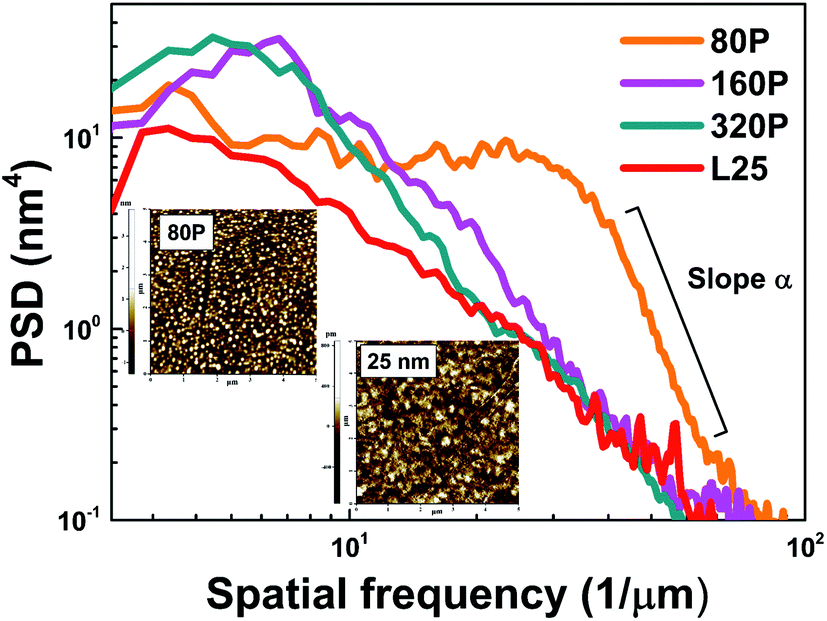 | ||
| Fig. 1 The power spectral densities of LSMO films (80P, 160P, 320P and L25) obtained from 5 μm × 5 μm AFM images (inset) and the value of α represent an exponent value of −4.9. | ||
In the case of 80P sample, the fast decay of spectra scales with a slope of α = −4.9, which is attributed to a 3D island growth of LSMO as well be seen in the inset of Fig. 1.16 On the contrary, as the formation of LSMO changes from nanoparticles to a layer, condensation of LSMO grains becomes a dominant growth process bringing about smaller α values in the spectra. In particular, it is interesting to note that 320P sample is in the middle state between nanoparticles and layers. This result presents a coalescence of nanoparticles with a higher density, which results dense particles to exhibit a characteristics close to a layer.
In order to investigate the effect of ferromagnetic LSMO buffer on the flux pinning of GdBCO, the magnetic field dependences of the critical current density Jc of GdBCO films on top of LSMO nanoparticles and layers were measured and were displayed in Fig. 2(a) and (b), respectively. As is clearly shown, GdBCO films with the LSMO buffers exhibit huge enhancement of Jc compared to pristine GdBCO film over the whole magnetic field region, regardless of the form of LSMO, indicating that the ferromagnetic LSMO buffers provide an effective pinning. It is worth to note that the degree of enhancement of Jc decreases upon increases of both the density of nanoparticles and the thickness of LSMO layer. Even though the 320P sample shows a characteristic close to a LSMO layer, it's Jcs are found to be much lower than those of the L25 sample. This result manifests a possibility of an existence of another pinning besides the magnetic pinning by LSMO.
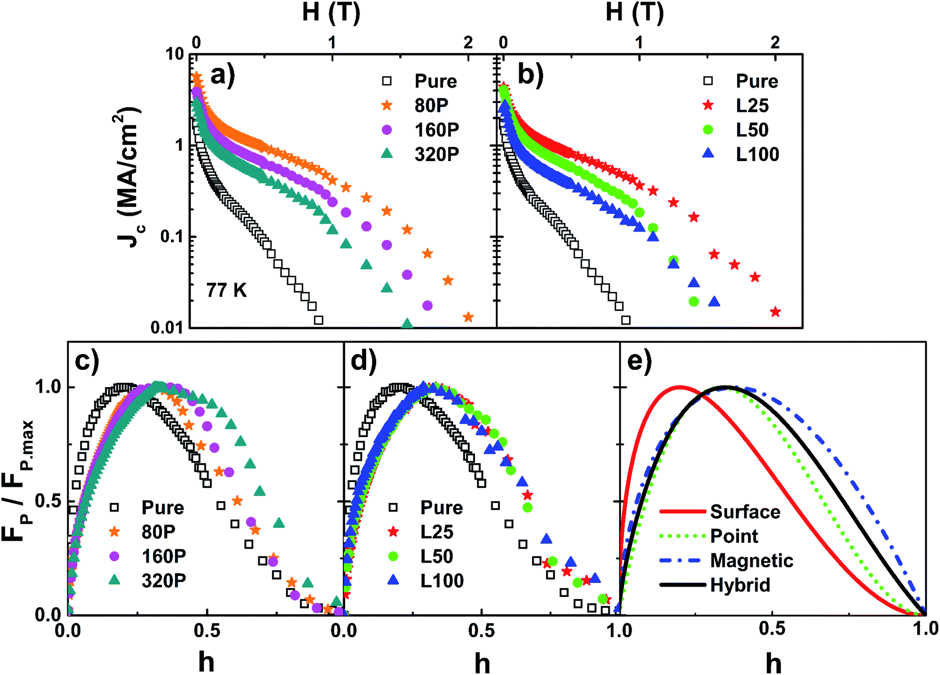 | ||
| Fig. 2 The critical current density, Jc as a function of magnetic field for GdBCO on LSMO (a) nano-particles and (b) layers samples. The plots of the experimental data with Dew-Hughes' scaling law for GdBCO on LSMO (c) nano-particles and (d) layers. (e) The corresponded results of theoretical Dew-Hughes' scaling of the flux pinning force; solid line is the core-surface pinning, dotted line is the core-point pinning and dashed-dotted line is magnetic pinning. | ||
For an in-depth evaluation of the pinning mechanism of the GdBCO/LSMO system, the flux pinning forces FP (Fp = Jc × μ0H) are scaled with the Dew-Hughes' formula, Fp/Fp.max ∼ hp(1 − h)q, where p and q are characteristic exponents, and h is the reduced field expressed by h = H/Hc2.20 It is experimentally found that the upper critical field (Hc2) can be replaced by the irreversibility field (Hirr) with the criterion of 103 A cm−2 for HTSC.21,22 Fig. 2(c) and (d) show the field dependence of the normalized pinning force Fp/Fp.max for the GdBCO films grown on LSMO nanoparticles and LSMO layers, respectively. For the LSMO nanoparticles, the shape of curves is changing with the particle density, whereas the shape of curves for the LSMO layer is remained to be the same regardless of the LSMO thickness. These results imply that pinning mechanisms in two types of LSMO buffer may be different. For direct comparison of the flux pinning mechanism, the functions of four types of pinning, (i) core-surface (p = 0.5, q = 2), (ii) core-point (p = 1, q = 2), (iii) magnetic-volume (p = 0.5, q = 1), and (iv) hybrid pinning with the equal contribution of core-point and magnetic-volume pinning (p = 0.7, q = 1.5) are visualized in Fig. 2(e). Comparing Fig. 2(c) and (d) with Fig. 2(e), it can be confirmed that LSMO buffer provides different contributions to pinning depending on the formation of LSMO. For the case of GdBCO on LSMO layers, all the films reveal an identical flux pinning mechanism of hybrid pinning regardless of the LSMO thickness. For the case on LSMO nanoparticles, however, the pinning mechanism seems to depend on the nanoparticle density. The 80P sample shows core point pinning and the curve of 160P starts to deviate from the curve of core pinning. The curve of 320P is different from those of other nanoparticles and is rather similar to those of LSMO layers, but the contribution of core point pinning appears to be low. Different pinning mechanisms upon the formation of LSMO indicate the possibility of structural distortion in GdBCO matrix induced by the different strain states of LSMO. In order to investigate the source of pinning mechanism, investigation on the local structures of both LSMO and GdBCO films are thoroughly performed.
Structural deformation of LSMO can cause changes both on the electronic configuration and on the inter-atomic distances, which extend through a whole lattice. These changes would be reflected in the Jahn–Teller distortion of MnO6 octahedron governing the magnetic property of LSMO. We investigate the local structure of LSMO by means of the Mn K-edge EXAFS spectroscopy. In order to gain an information on local atomic displacement of the Mn–O bond in the MnO6 octahedron, an isolated contribution of the Mn–O bond was first filtered by an inverse Fourier transformation of EXAFS (not shown here), and then the Mn–O pair distribution functions (PDF) were calculated from the filtered spectra by using the EXAFS regularization technique.23 The well-defined PDFs signify a single Mn–O bond distance existing in the MnO6 octahedron, providing the average Mn–O bond distance corresponds to a peak of the function. As can be seen from Fig. 3(a), the average Mn–O bond tends to elongate as the formation of LSMO changes to a layer form. Distribution of the Mn–O bonds in the MnO6 octahedron is evaluated by using a Gaussian fitting based on the reference values of a short and a long bonds between manganese and oxygen ions.24 As displayed in Fig. 3(b)–(e), it is possible to identify a dominant contribution from clearly separated a short and a long Mn–O bonds. Since the MnO6 octahedron consist of four in-plane and two out-of-plane Mn–O bonds, the predominant bond in the results may be considered as a contribution of the in-plane bonds. In the cases of 80P and 160P samples, a contribution from short-bonds is larger (average RMn–O contraction), which indicates the Jahn–Teller elongation of the MnO6 octahedron in the out-of-plane direction. On the contrary, as the formation of LSMO converts to a layer, a contribution from long-bonds becomes more dominant (average RMn–O elongation), indicating the Jahn–Teller elongation in the in-plane direction.
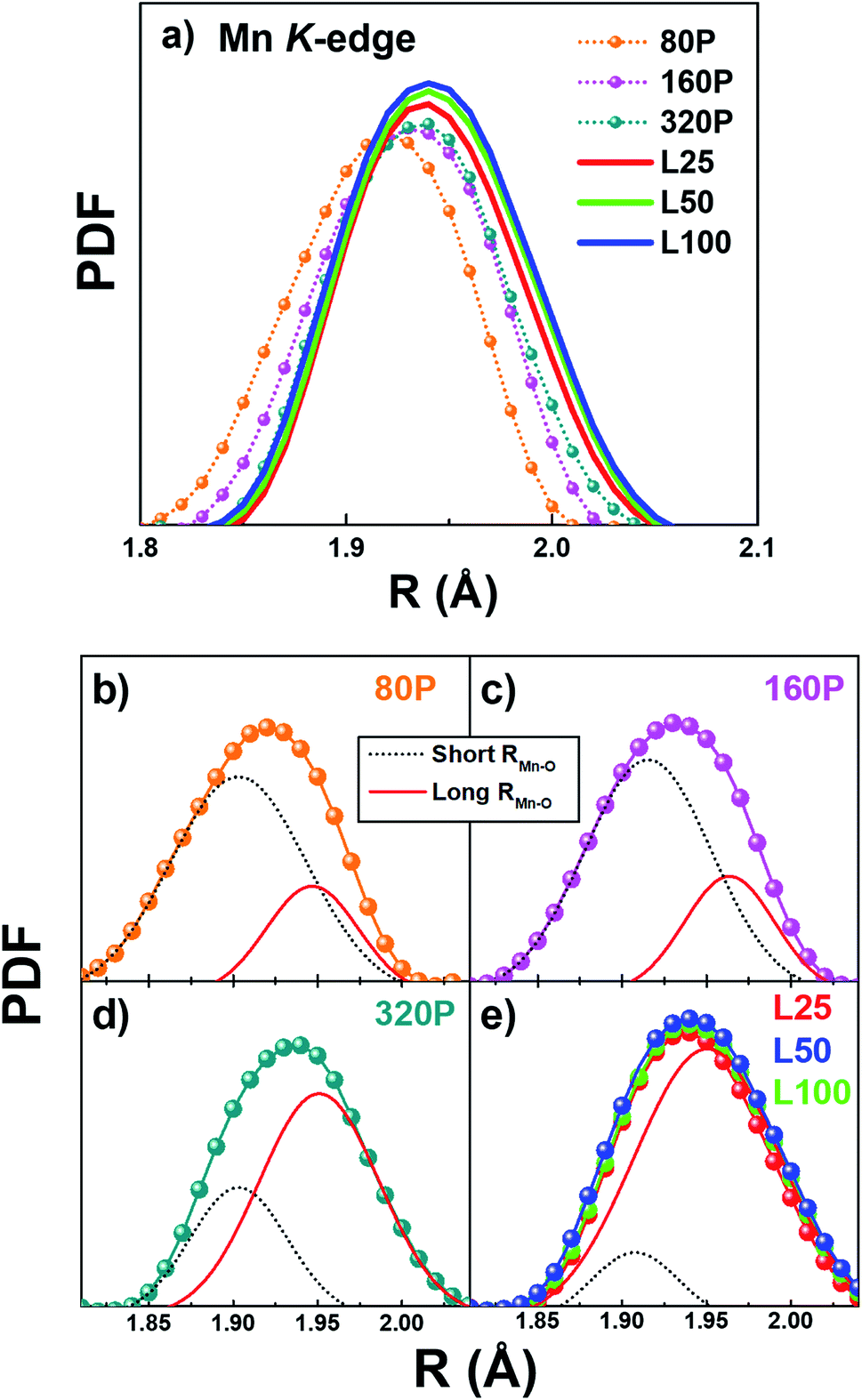 | ||
| Fig. 3 (a) Mn–O pair distribution function (PDF) for GdBCO on each LSMO type. (b)–(e) Gaussian fitting results on an initial experimental data: solid and dotted lines are the pair distribution of short and long Mn–O bonds in MnO6 octahedron. | ||
An effect of different formations of LSMO in our system is summarized in Fig. 4, in which the Mn–O bond distances and magnetic responses of all the samples are compared. Fig. 4(a) shows the in-plane Mn–O bond distances obtained from a fitting process of Fig. 3 as a function of LSMO formation. The in-plane Mn–O bond distance rapidly increases as the number of laser pulses increases from 80P to 320P, and then is saturated with a value of ∼1.95 Å as the formation of LSMO is converted to a layer. The reason for such an elongation of Mn–O bond may be attributed to the dissimilarity of lattice constants between LSMO and STO substrate (lattice mismatch of 0.64%), indicating a presence of tensile strain in the LSMO films. In our previous study,16 we found that LSMO nanoparticles on STO substrate are rather under a compressive strain state, which is independent on the tensile strain produced by lattice mismatch until they are grown into a form of layer.
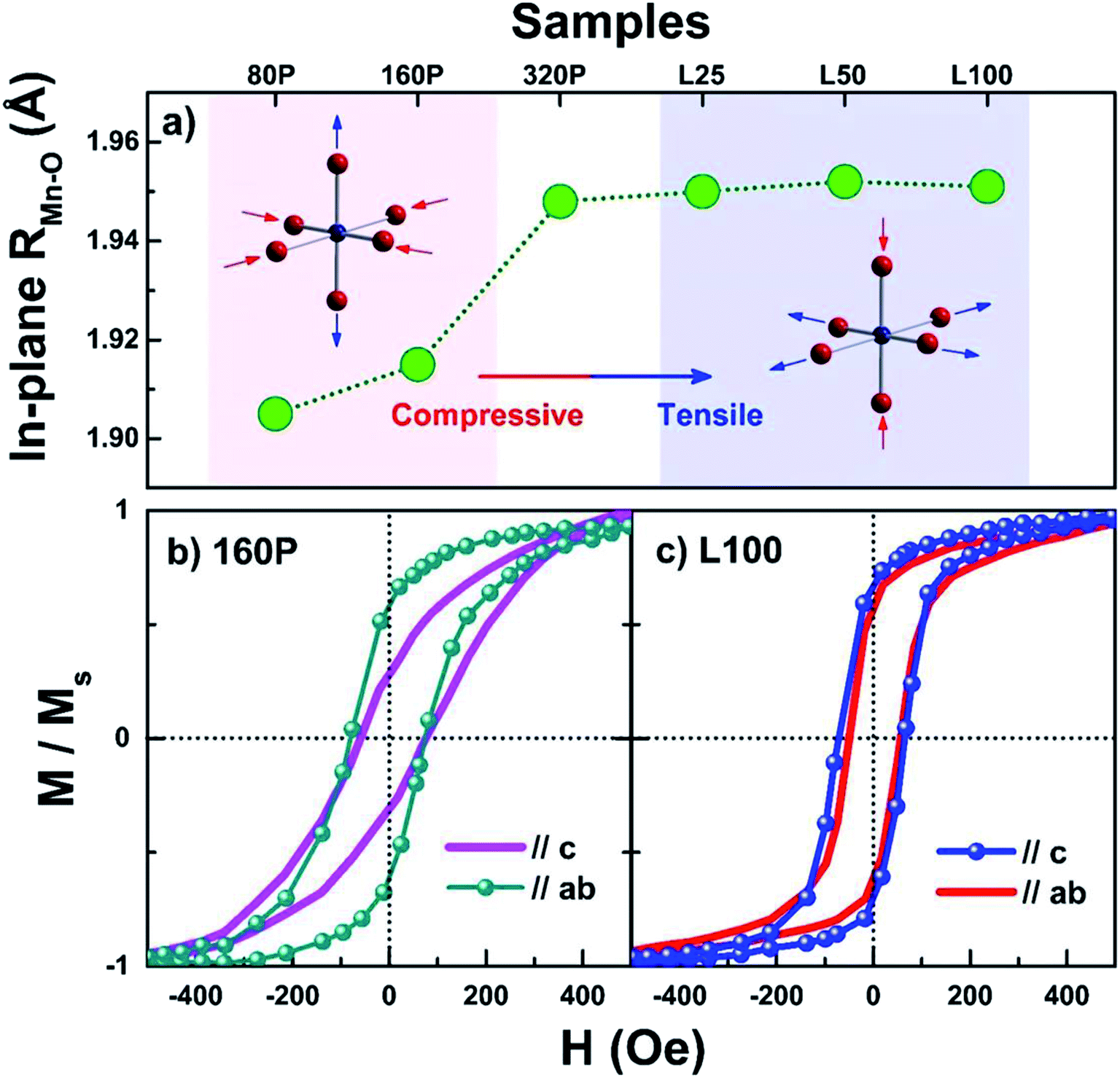 | ||
| Fig. 4 (a) In-plane Mn–O bond distance as a function of samples. The normalized in-plane and out-of-plane magnetization curves for (b) 160P and (c) L100. | ||
The Jahn–Teller elongation which buckles the Mn–O bond could lead to a strong electron–phonon coupling due to Jahn–Teller splitting of the Mn3+ ion.25–29 Consequently it affects the double-exchange of eg electron hopping between ferromagnetically coupled Mn3+ and Mn4+, which indicates the occurrence of charge orbital ordering.27,29–31 In particular, a contraction of MnO6 octahedron in in-plane direction is accompanied by the stabilization of the d3z2−r2 orbital with an increase in the out-of-plane ferromagnetic interaction, as observed in the case of LSMO nanoparticles.32,33 For the case of a contraction of MnO6 octahedron in the out-of-plane direction, the stabilization of the dx2−y2 orbital with a reduction in the out-of-plane ferromagnetic interaction is expected. Different directional ferromagnetic interaction of LSMO nanoparticles and layer is also reflected in the M–H hysteresis loops measured at 150 K displayed in Fig. 4(b) and (c). It can be clearly seen that the field dependences of magnetization and the coercive fields are different depending upon the LSMO formation, which are sensitive to the strain state. In the case of LSMO nanoparticles, compressive strain results in a reduction of the in-plane Mn–O bond and induce a rotation of easy axis large anisotropy in magnetization. On the contrary, the tensile strained LSMO layers exhibit an out-of-plane magnetization irrespective of the direction of magnetic field, which is necessary for magnetic flux pinning. It may be due to a complicate competition between the Jahn–Teller elongation and the charge orbital ordering in the MnO6 octahedron.29–31 The structural and magnetic disparities between LSMO nanoparticles and layer may alter the superconducting property of the top GdBCO film in different ways.
We investigated the effect of structural deformation of GdBCO films under different strain states of LSMO. The Cu–O bond lengths in the CuO2 plane of GdBCO films for all the samples are evaluated from the analysis of Cu K-edge EXAFS measurements.16 The Cu–O bonds are observed to have a close correlation with the Mn–O bond length, which may be attributed to the inextricable link of top GdBCO layer to the bottom LSMO buffer, and the length ratios of the Cu–O bond to the Mn–O bond are displayed in Fig. 5(a). The bond ratio drastically decreases as the nanoparticle density increases and reaches to a minimum for 320P sample, and becomes nearly constant as LSMO forms a layer. As a result, the Cu–O bonds in GdBCO deposited on the LSMO nanoparticles are elongated with much less strain, while they are gradually contracted in the LSMO layer. The deformation in local atomic structure is found to be closely related to the critical temperature, Tc, and the Tc values of GdBCO/LSMO layer are higher than those of GdBCO/LSMO nanoparticles, as reported in our previous study.16 It suggests that the formation of LSMO has a critical effect on local atomic displacement and can also provide charge transfers in the CuO2 plane. Moreover, according to the bond contraction pairing (BCP) model,34,35 when the formation of Cooper pairs is suppressed by an elongation of the Cu–O bond, there is a possibility of creating non-superconducting state with a dimension close to the coherence length of GdBCO. Thus, the Jc enhancements observed in the GdBCO/LSMO nanoparticles can be understood by the effect of non-superconducting cores created by lattice disorder, which further appears as core pinning mechanism in Fig. 2(c).
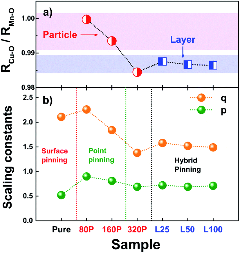 | ||
| Fig. 5 (a) Bond ratio between Mn–O and Cu–O bond as a function of samples. (b) The variation of characteristic exponents upon the samples, obtained from the Dew-Hughes' scaling in Fig. 2(b) and (c). | ||
Change in the flux pinning mechanism can be numerically verified by the behaviors of the Dew-Hughes' scaling constants as a function of samples as shown in Fig. 5(b). Due to a combination of possible pinning mechanisms, the values of the constant may not be perfectly matched to the theoretical values, however, the effect of LSMO formation on the flux pinning can be predicted. As shown in Fig. 5(b), the values of p remain to be constant between 0.7 and 0.9 while a drastic change is observed in the q values. It is interesting to note that the trend of q is quite consistent with the trend of the bond ratio displayed in Fig. 5(a). This indicates that the flux pinning mechanism is closely related to the structures of upper and bottom layers. In the regime where the Cu–O bond is relatively elongated, core-pinning mechanism is dominant in GdBCO films. As the Cu–O bond is contracted due to the strain of LSMO, the flux pinning mechanism changes from core pinning to hybrid pinning, which is attributed to both magnetic- and core-pinnings. It is interesting to note that for the 320P sample which has the shortest Cu–O bond among the samples, the q value is lower than that of LSMO layer samples, which suggests a reduction of core-pinning. This estimation can be inferred through the fact that the normalized Fp function becomes convex at higher field sides as the contribution of core-point pinning decreases in the hybrid pining mechanism. As a result, it is shown that the transition of flux pinning mechanism is associated with the LSMO-induced Cu–O bond buckling, which points out that magnetic pinning may work better at an appropriate state of the Cu–O bond. The fact that the GdBCO films on LSMO nanoparticles exhibit a weak contribution of magnetic pinning even though of which coercive field is greater than that of LSMO layer suggests that proper structural compatibility between GdBCO and LSMO lattice is an essential condition for operation of magnetic pinning. Moreover, the use of a ferromagnetic LSMO buffer layer appears to be an attractive method from an application point of view as high Jc can be achieved through the hybrid pining with core-point pinning.
4. Conclusion
A comparative study on the effects of two types of LSMO buffers (nanoparticles and layers) on the flux pinning properties of the GdBCO/LSMO system shows that the strain states of LSMO can alter the local structure of GdBCO and directly affect the flux pinning property. In both cases, the values of Jc significantly enhanced than those of the GdBCO film without LSMO buffer although the mechanisms of Jc enhancements seem to be different. For the GdBCO films on LSMO layers, hybrid pinning of magnetic pinning and core point pinning is a dominant pinning mechanism, while core pining becomes a major pinning mechanism for the GdBCO on LSMO nanoparticles. The relative contraction or elongation of the Cu–O bond respect to the Mn–O bond induced by different strain states of LSMO is found to directly affect the flux pinning properties and to result in different pinning mechanisms. This study of comparison between two LSMO types therefore offers better understanding on the flux pinning mechanism of GdBCO/LSMO system, which is essential for realizing Jc enhancement by LSMO buffer layer, which is suitable for practical applications.Conflicts of interest
There are no conflicts to declare.Acknowledgements
This work was supported by the National Research Foundation of Korea (NRF) grant funded by the Korean government (MSIT) (NRF-2018R1A2B6004784).References
- J. L. Macmanus-Driscoll, S. R. Foltyn, Q. X. Jia, H. Wang, A. Serquis, L. Civale, B. Maiorov, M. E. Hawley, M. P. Maley and D. E. Peterson, Nat. Mater., 2004, 3, 439 CrossRef CAS.
- T. A. Campbell, T. J. Haugan, I. Maartense, J. Murphy, L. Brunke and P. N. Barnes, Phys. C, 2005, 423, 1 CrossRef CAS.
- T. Horide, K. Taguchi, K. Matsumoto, N. Matsukida, M. Ishimaru, P. Mele and R. Kita, Appl. Phys. Lett., 2016, 108, 082601 CrossRef.
- T. Horide, N. Matsukida, M. Ishimaru, R. Kita, S. Awaji and K. Matsumoto, Appl. Phys. Lett., 2017, 110, 1 CrossRef.
- C. F. Tsai, Y. Zhu, L. Chen and H. Wang, IEEE Trans. Appl. Supercond., 2011, 21, 2758 CAS.
- L. N. Bulaevskii, E. M. Chudnovsky and M. P. Maley, Appl. Phys. Lett., 2000, 76, 2594 CrossRef CAS.
- D. B. Jan, J. Y. Coulter, M. E. Hawley, L. N. Bulaevskii, M. P. Maley and Q. Jia, Appl. Phys. Lett., 2003, 82, 778 CrossRef CAS.
- S. C. Wimbush, J. H. Currell, C. F. Tsai, H. Wang, Q. X. Jia, M. G. Balmire and J. L. MacManus-Driscoll, Supercond. Sci. Technol., 2010, 23, 045019 CrossRef.
- A. K. Jha, N. Khare and R. Pinto, J. Supercond. Novel Magn., 2014, 27, 1021 CrossRef CAS.
- A. K. Jha, N. Khare and R. Pinto, J. Appl. Phys., 2011, 110, 113920 CrossRef.
- J. Huang, C. F. Tsai, L. Chen, J. Jian, K. Yu, W. Zhang and H. Wang, IEEE Trans. Appl. Supercond., 2015, 25, 3 Search PubMed.
- T. Donchev, V. Tsaneva, T. Nurgaliev, L. Gravier, J. P. Ansermet, I. Petrov, V. Petrova, V. W. Matz, R. Groetzschel, S. Pignard and H. Vincent, Vacuum, 2002, 69, 243 CrossRef CAS.
- T. Petrisor Jr, M. S. Gabor, C. Tiusan, V. Galluzzi, G. Celentano, S. Popa, A. Boulle and T. Petrisor, J. Appl. Phys., 2012, 112, 053919 CrossRef.
- A. L. Kozlovskiy and M. V. Zdorovets, J. Mater. Sci.: Mater. Electron., 2019, 30, 11819 CrossRef CAS.
- K. K. Kadyrzhanov, D. I. Shlimas, A. L. Kozlovskiy and M. V. Zdorovets, J. Mater. Sci.: Mater. Electron., 2020, 31, 11729 CrossRef CAS.
- J. Y. Oh, C. Y. Song, Y. J. Ko, D. S. Yang and B. Kang, Supercond. Sci. Technol., 2020, 33, 075002 CrossRef.
- C. P. Bean, Rev. Mod. Phys., 1964, 36, 31 CrossRef.
- H. P. Wiesinger, F. M. Sauerzopf and H. W. Weber, Phys. C, 1992, 203, 121 CrossRef CAS.
- B. Ravel and M. Newville, J. Synchrotron Radiat., 2005, 12, 537 CrossRef CAS.
- D. Dew-Hughes, Philos. Mag., 1974, 30, 293 CrossRef CAS.
- A. Crisan, V. S. Dang, G. Yearwood, P. Mikheenko, H. Huhtinen and P. Paturi, Phys. C, 2014, 503, 89 CrossRef CAS.
- M. R. Koblischka, A. J. J. van Dalen, T. Higuchi, S. I. Yoo and M. Murakami, Phys. Rev. B: Condens. Matter Mater. Phys., 1998, 58, 2863–2867 CrossRef CAS.
- D. S. Yang and G. Bunker, Phys. Rev. B: Condens. Matter Mater. Phys., 1996, 54, 3169 CrossRef CAS.
- A. N. Ulyanov, D. S. Yang and S. C. Yu, J. Phys. Soc. Jpn., 2003, 72, 1204 CrossRef CAS.
- N. Zener, Phys. Rev., 1951, 82, 403 CrossRef.
- P. W. Anderson and H. Hasegava, Phys. Rev., 1955, 100, 675 CrossRef CAS.
- A. J. Millis, P. B. Littlewood and B. I. Shraiman, Phys. Rev. Lett., 1995, 74, 5144 CrossRef CAS.
- M. B. Salamon and M. Jaime, Rev. Mod. Phys., 2001, 73, 583 CrossRef CAS.
- M. Uehara, S. Mori, C. H. Chen and S. W. Cheong, Nature, 1999, 399, 560 CrossRef CAS.
- H. Röder, J. Zang and A. R. Bishop, Phys. Rev. Lett., 1996, 76, 1356 CrossRef.
- B. Dabrowski, X. Xiong, Z. Bukowski, R. Dybzinski, P. W. Klamut, J. E. Siewenie, O. Chmaissem, J. Shaffer, C. W. Kimball, J. D. Jorgensen and S. Short, Phys. Rev. B: Condens. Matter Mater. Phys., 1999, 60, 7006 CrossRef CAS.
- L. Hu, Z. Sheng, X. Hu, R. Zhang, B. Wang, W. Song and Y. Sun, J. Phys. D: Appl. Phys., 2012, 45, 175002 CrossRef.
- A. Sadoc, B. Mercey, C. Simon, D. Grebille, W. Prellier and M.-B. Lepetit, Phys. Rev. Lett., 2010, 104, 046804 CrossRef.
- G. Deutscher and P. G. de Gennes, C. R. Phys., 2007, 8, 937–941 CrossRef CAS.
- G. Deutscher, Appl. Phys. Lett., 2010, 96, 122502 CrossRef.
| This journal is © The Royal Society of Chemistry 2020 |