DOI:
10.1039/D0RA06309F
(Paper)
RSC Adv., 2020,
10, 31442-31452
Photocatalytic partial oxidation of methanol to methyl formate under visible light irradiation on Bi-doped TiO2 via tuning band structure and surface hydroxyls†
Received
20th July 2020
, Accepted 20th August 2020
First published on 26th August 2020
Abstract
Preparing visible light responsive catalysts for partial oxidation of methanol to methyl formate is a challenging issue. This work addresses the synthesis, characterization and theoretical calculation of Bi doped TiO2 catalysts as well as their photocatalytic performance and reaction mechanism for MF synthesis from methanol. The catalysts were prepared by a simple wet chemical method. The results of the characterization and theoretical calculation evidenced that bismuth was intercalated in the lattice of anatase by the substitution of titanium. Impurity levels were formed in the valence band, conduction band and between the two bands. The Bi 6s and 5p orbitals contributed to the formation of the impurity levels. The photo-excited electrons transited from the valence band via impurity levels, formed by Bi 6s orbitals, to the conduction band. The doping of Bi enhanced surface hydroxyls, reduced the band gaps and raised the valence band edges (VBE) of the Bi doped catalyst. The Bi doped catalysts were visible light responsive due to the reduced band gap. The surface hydroxyls were beneficial to the methanol conversion, and the rise of the VBE enhanced the redox potential of the photogenerated holes. Only moderate redox potentials and sufficient surface hydroxyls could lead to high methanol conversion and MF selectivity. This study is of great significance to the development of the photocatalytic synthesis theory and provides a green route for MF synthesis from methanol.
Introduction
From coal via methanol to methyl formate (MF), a key intermediate to produce important chemicals such as formic acid, formamide, acetic acid and ethylene glycol,1–5 is a promising route in coal chemical industry.6 The photocatalytic synthesis of MF from methanol is a new green route and has become a hot research topic in recent years due to the ambient reaction conditions and high MF selectivity.7–12
TiO2-based materials have been widely studied for many reactions.13–21 The secondary alcohol photo-oxidation on TiO2 and ZnO was first reported by J. Cunningham and B. K. Hodnett in 1981,22 and Liu et al. reported the photocatalytic methanol oxidation on MoO3/TiO2 and TiO2 as early as 1985.23 H. Kominami et al. studied this reaction on an anatase-type TiO2 in 2010.11 In our previous studies, we have reported Au, Ag, Au–Ag alloy and Cu nanoparticles supported on TiO2 and ZnO for photocatalytic partial oxidation of methanol at 15 °C–45 °C since 2014.7–9,12 J. C. Colmenares et al. studied the same reaction on Pd–Au/TiO2 and Pd–Cu/TiO2.10,24 However, all studies used UV irradiation as light source so far. It has great potential of application if the reaction can occur under the irradiation of visible light.
Titania is an effective photocatalyst for partial oxidation of methanol because, on the one hand, there are plenty of surface hydroxyls which can react with methanol molecules to give rise to methoxy, a key intermediate for the reaction, at room temperature without irradiation,2,3,25 and on the other hand, it has suitable valence band edge that can generate photoexcited holes being able to oxidize methoxy to formaldehyde under UV irradiation.7–10,12,24 However, TiO2 cannot work as a photocatalyst for partial oxidation of methanol to MF under visible light irradiation due to the wide band gap (3.0 eV).26 Even so, TiO2 is still the most promising visible light responsive photocatalyst for this reaction if proper modification is carried out. Doping TiO2 with metallic or non-metallic elements can form impurity energy levels between the conduction band and valence band of TiO2, and thus was often employed to lower the threshold energy for excitation in order to utilize a wide range of solar energy.27–32 Such a modification usually works in a lot of photocatalytic processes such as the degradation of organics,31,33–35 but it is a challenge in photocatalytic partial oxidation process, especially for partial oxidation of methanol. This is because the doping process can cause not only the reduction of the band gap but also the shift of valence and/or conduction band edges, leading to the variation of the redox potential of the photoexcited holes and thus the partial oxidation reaction. In addition, the doping may change the surface hydroxyls of titania as well, remarkably influencing the methanol conversion and methyl formate selectivity.
Bismuth has d10 electronic configuration. Bi-doped TiO2 extends the spectral range of TiO2 to visible light responsive region and inhibits electron–hole recombination, and thus has been extensively studied for the degradation of organic pollutants,27,29,33,35,36 antibacterial application37 and photocathode for fuel cell38 etc. However, it is seldom used in photocatalytic partial oxidation reactions due to the more complicated reaction mechanism. In this study, Bi-doped TiO2 was prepared by the wet chemical method and the photocatalytic performance for partial oxidation of methanol to MF was investigated. The band structure and surface species of the catalyst were characterized by a UV-visible spectrometer (UV-vis), electrochemical workstation, X-ray photoelectron spectroscopy (XPS) and a Fourier transform infrared spectrometer (FTIR) etc., and the band structure and optical properties before and after doping was studied by the first principal theory as well. The purpose of this study is to investigate the effect of the Bi doping on the band structure, especially the valence band edges and band gaps, and the surface hydroxyls, as well as their effect on the photocatalytic performance for partial oxidation of methanol to MF under visible light irradiation.
Experimental
Materials
Tetrabutyl titanate (TBOT), Bi(NO3)3·5H2O, absolute ethanol and methanol were purchased from J & K Scientific. All chemicals were used as received.
Catalyst preparation
Typically, 6.8 ml of TBOT was dissolved in 60 ml of absolute ethanol and keep stirring for 30 min to obtain solution A. A certain amount of Bi(NO3)3·5H2O was dissolved in a solution of 30 ml of absolute ethanol and 8 ml of deionized water to obtain solution B. Add solution B to solution A dropwise with vigorously stirring, and keep stirring for 8 hours. The obtained solid was washed with deionized water and absolute ethanol several times and dried under supercritical condition (245 °C, 8 MPa), and finally the catalyst was obtained after calcination at 500 °C for 2 h, and labelled as XBi-TiO2, where X = n(Bi/Ti) is the percentage of Bi in the catalyst.
Catalyst characterization
X-ray diffraction (XRD) profiles were obtained using a Bruker D8 Advance diffractometer with a Cu Kα radiation operated at 40 kV. The scanning range (2θ) was 10–80°. The morphology of the samples was investigated by a FEI Tecnai S-Twin field emission high resolution transmission electron microscope (HR-TEM). The optical property was determined by a UVIKON/XL UV-vis diffuse reflectance spectrometer (UV-vis) with a scanning range of 200–800 nm. The X-ray photoelectron spectra (XPS) of the catalysts were recorded by a Kratos Amicus spectrometer using an Al K (1486.6 eV) radiation source. The binding energy (BE) was adjusted by the C1s transition at 284.6 eV. The Fourier transform infrared (FTIR) spectrum was recorded on a Bruker Vertex 70 FTIR spectrometer. The temperature programmed reduction with hydrogen (H2-TPR) was performed with a Micromeritics AutoChem 2910 analyzer. The gas mixture is 10% H2 balanced with N2 and the flow rate is 50 mL min−1. The heating rate is 10°C min−1 10 mg sample was loaded in the quartz tube for each run. The N2 adsorption–desorption isotherms were measured using a Micromeritics ASAP 2020 analyzer. The specific surface areas were calculated by the Brunauer–Emmett–Teller (BET) equation from the N2 adsorption isotherm. The pore structure parameters were obtained from the adsorption branch using the BJH model. Prior to the experiment of adsorption, all samples were degassed under vacuum at 150 °C for 12 h. The electrochemical properties of the catalyst were carried out in liquid junction cells on a Shanghai Chenhua CHI700E Chemical Station.
Photocatalytic reaction
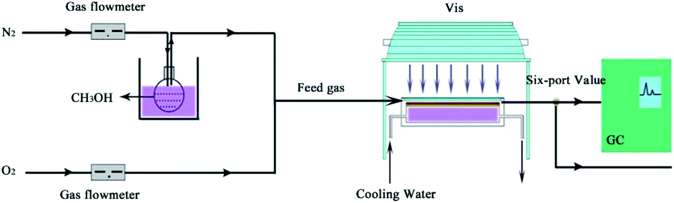
The photocatalytic activity of the catalyst was performed in a continuous flow magnesium–aluminium alloy reactor with a rectangle quartz window on the top and a dividing wall-type heat exchanger connected to the back of the reactor.7 Three pieces of rectangle glass which were used as the catalyst holders were installed in the bottom of the reactor, with a thermocouple fixed in touch with the middle catalyst holder. The catalyst of 0.02 g was loaded on the holders for each run. The dimension of each piece of the glass holders was 26 mm × 80 mm × 1 mm. The cooling water flowed through the heat exchanger to maintain a constant temperature. A 500 W xenon lamp without filter was positioned 10 cm over the quartz window of the reactor (light intensity, 100 mW cm−2). A gas mixture containing 1–3 vol% methanol and 0.17–20 vol% O2 balanced with N2 was supplied at the flow rate of 50 ml min−1 into the reactor. Oxygen and nitrogen in the mixture were measured by mass flowmeters. The reaction temperature was from 15 to 45 °C. The products were qualified by a GC-MS and a LC-MS in batches and quantified on line by a Shimadzu GC2014C equipped with a FID detector (Fig. 1).
 |
| | Fig. 1 Schematic diagram of the reaction process. | |
The methanol conversion was obtained by eqn (1), assuming the volume flow rate was constant before and after the reaction due to the low reactant content in the feed gas.
| |
 | (1) |
where
C is the methanol conversion, %;
ρM0 is the initial methanol content, mg L
−1;
ρM1 is the methanol content in the off gas after reaction, mg L
−1.
| |
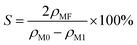 | (2) |
where
S is the methyl formate selectivity, %;
ρMF is the methyl formate content in the off gas after reaction, mg L
−1.
The formation rate of methyl formate was calculated by the following eqn (3).
| |
 | (3) |
where Fr is the formation rate, mmol g
−1 h
−1;
ρM0 is the initial methanol content in feed gas, mg L
−1;
V is the flow rate of feed gas, L h
−1;
C is the methanol conversion, %;
S is the methyl formate selectivity, %;
M is the molecular weight of methanol, g mol
−1;
m is the weight of catalyst, g.
Results and discussion
Catalyst characterization
Fig. 2 shows the XRD patterns of TiO2 and Bi-doped TiO2. The diffraction peaks at 25.35°, 37.60°, 48.10°, 53.89°, 55.30°, 63.20°, 69.00°, 70.18°, 75.37° are assigned to the (101), (004), (200), (105), (211), (204), (116), (210), (215) faces of anatase, tetragonal crystal system (reference code 00-002-0406). No diffractions attributed to bismuth species could be identified in the profiles. With the increase of the Bi content from 0.25 wt% to 2.00 wt%, the width of the (101) diffraction peak is broadened and the intensity is weakened gradually. The average crystal sizes of anatase becomes smaller and smaller from 9.47 to 7.60 nm, calculated by the Debye–Scherrer's equation. The lattice parameters of each sample were calculated and listed in Table 1. It can be observed that the cell volume gradually swells with increasing the content of bismuth, indicating that Bi was doped in the lattice of anatase.
 |
| | Fig. 2 XRD patterns of (a) bare TiO2, (b) 0.25Bi-TiO2, (c) 0.5Bi-TiO2, (d) 1Bi-TiO2, and (e) 2Bi-TiO2. | |
Table 1 The lattice parameters and average size of anatase
| Samples |
Lattice parameter (Å) |
Crystal size, nm |
Cell volume, Å3 |
| a = b |
c |
| Bare TiO2 |
3.7853 |
9.4944 |
9.47 |
136.0375 |
| 0.25Bi-TiO2 |
3.7869 |
9.5001 |
9.45 |
136.2365 |
| 0.5Bi-TiO2 |
3.7866 |
9.5036 |
9.17 |
136.2623 |
| 1Bi-TiO2 |
3.7880 |
9.5040 |
8.58 |
136.3704 |
| 2Bi-TiO2 |
3.7906 |
9.5007 |
7.60 |
136.5137 |
|
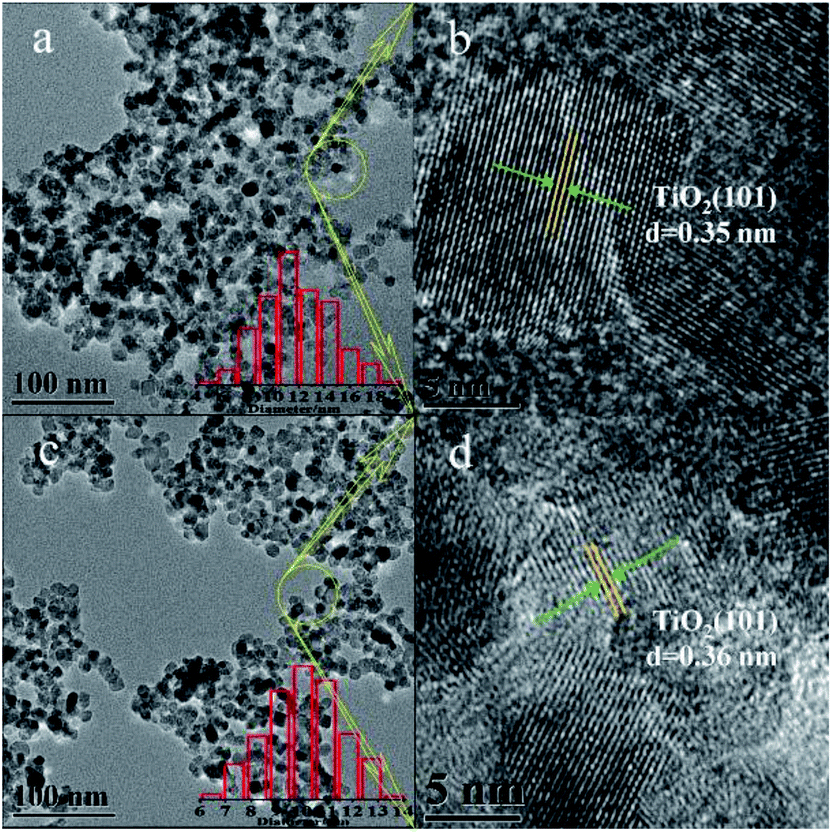
Fig. 3 and s1† show TEM images of bare TiO2 and XBi-TiO2 samples. The size of the nanoparticles distributed uniformly and it becomes smaller and smaller with the increase of the Bi content, which is in line with the result calculated by the Debye–Scherrer's equation from the XRD profile. The d(101) spacing of anatase can be observed from the HR-TEM images, which is the only phase that can be identified from the lattice fringes. The d spacing enlarges with increasing the Bi content (Fig. 3d, s1h and j†). This is consistent with the cell parameters listed in Table 1, suggesting that Bi was intercalated into the lattice of anatase. This is consistent with the result calculated from the XRD.
 |
| | Fig. 3 TEM images of (a and b) bare TiO2, (c and d) 0.5Bi-TiO2. | |
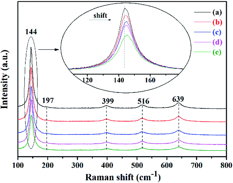
Raman spectra can also evidence the intercalation of Bi into the lattice of anatase. As shown in Fig. 4, the bands at 144, 197, 399, 516 and 639 cm−1 are the Raman active fundamentals of anatase.29,36,39,40 The three Raman bands at 144, 197 and 639 cm−1 are definitely assigned to the three Eg modes, the band at 516 cm−1 is from the doublet of A1g and B1g modes and that at 399 cm−1 is attributed to the B1g mode. It can be observed that the Eg bands centered at 144 cm−1, attributed to the shift of Ti–O–Ti frame of anatase, shift to higher position, the peak width is broadened and the intensity of the peaks is weakened with the increase of the Bi content, indicating poorer crystallinity and evidencing the intercalation of Bi into the lattice of anatase from another angle.
 |
| | Fig. 4 Raman spectra of (a) bare TiO2, (b) 0.25Bi-TiO2, (c) 0.5Bi-TiO2, (d) 1Bi-TiO2, and (e) 2Bi-TiO2. | |
Fig. 5A shows the UV-visible diffuse reflection spectra of bare TiO2 and XBi-TiO2 samples, and Fig. 5B shows the Kubelka–Munk plot of the samples.41 The bare TiO2 exhibits absorption edge at 400 nm, corresponding to 3.1 eV of the band gap. The absorption bands of the Bi doped samples exhibit obvious red shift. With the increase of the Bi content from 0.25 wt% to 2 wt%, the absorption band edge shifts from 407 nm to 427 nm, and the band gap energy varies from 3.04 eV to 2.90 eV. The absorption bands of the Bi doped samples extend to visible light region. The Bi dopant in the lattice of TiO2 can form impurity levels in the band gap of TiO2 and reduce the recombination of the photoexcited electron and hole pair, as well as the excitation energy.33–35,38,42 In addition, the doping process can result in oxygen vacancies in the lattice, which play the role of photoexcited electron traps and is beneficial to inhibiting the recombination of the electron and hole as well.
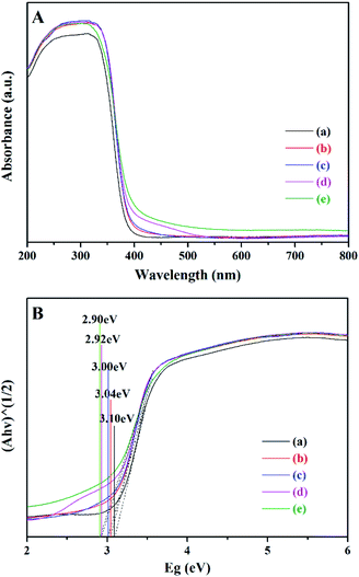 |
| | Fig. 5 UV-visible spectra (A) and Kubelka–Munk plot (B) of the samples. (a) Bare TiO2, (b) 0.25Bi-TiO2, (c) 0.5Bi-TiO2, (d) 1Bi-TiO2, and (e) 2Bi-TiO2. | |
The N2 adsorption–desorption results of all the five samples exhibit type IV isotherm, suggesting mesopores in these samples43 (see Fig. s2†). The bare TiO2, 1Bi-doped TiO2 and 2Bi-doped TiO2 show a H3 hysteresis loop and the samples 0.25Bi-doped TiO2 and 0.5Bi-doped TiO2 show a H1 hysteresis loop. The H1 loop is associated with the mesopores composed by relatively uniform particles and the H3 loop is often regarded as from the slit-like pores.43 However, it can be observed that the onset of the hysteresis loop starts from 0.8 of the relative pressure. Such a hysteresis loop is not from structure mesopores of the nanoparticles but from the pores of agglomerates composed by nanoparticles.44 As a result, the isotherms of the samples just indicates that the particle size of 0.25Bi-doped TiO2 and 0.5Bi-doped TiO2 was relatively evenly distributed while that of samples bare TiO2, 1Bi-doped TiO2 and 2Bi-doped TiO2 was unevenly distributed. The incompact pore structure is resulted from the supercritical drying process. Table 2 lists the specific surface area, pore volume, pore size and Bi content of the catalyst. The actual Bi content in each sample is slightly less than that of the nominal one. Although the pores in the samples were from the accumulation of the nanoparticles, it is easier to be dispersed and thus beneficial to the reaction.
Table 2 BET specific surface areas, pore volumes and Bi content of catalysts
| Samples |
SBET (m2 g−1) |
Pore volume (m3 g−1) |
Pore size (nm) |
Nominal value n(Bi/Ti) |
Actual value n(Bi/Ti) |
| Bare TiO2 |
100.60 |
0.16 |
6.65 |
0.00 |
0.00 |
| 0.25Bi-TiO2 |
112.30 |
0.35 |
9.43 |
0.25 |
0.23 |
| 0.5Bi-TiO2 |
131.50 |
0.41 |
9.64 |
0.50 |
0.44 |
| 1Bi-TiO2 |
106.80 |
0.28 |
8.62 |
1.00 |
0.93 |
| 2Bi-TiO2 |
103.50 |
0.23 |
7.80 |
2.00 |
1.96 |
Fig. 6 shows the normalized FTIR spectra of the samples. It is considered that the amount of the total surface (Ti, Bi)–O bond in each sample should be similar in the case that the Bi content in the sample varied from 0 to 2 wt%. Thus, the intensity variation of the (Ti, Bi)–O vibrations in the spectrum may be from the difference of the sample amount in the light spot due to the inhomogeneous blending of KBr and the sample for FTIR investigation. In order to compared the surface hydroxyls of each sample, the stretching vibrations of (Ti, Bi)–O, the band from 400 to 800 cm−1, of each sample are considered as equal or very close.45,46 Set the intensity of the Ti–O stretching vibration of any sample as a standard, and those of the other samples are normalized to the same level. So the whole spectrum of the sample other than the standard one may enlarge or reduce the same times as the Ti–O vibrations of the same sample. Such a treatment is expected to eliminate the operation errors for FTIR investigation.
 |
| | Fig. 6 FTIR spectra of (a) bare TiO2, (b) 0.25Bi-TiO2, (c) 0.5Bi-TiO2, (d) 1Bi-TiO2, and (e) 2Bi-TiO2. | |
The band around 3400 cm−1 is attributed to the stretching vibration of the surface hydroxyls.47–49 In comparison of this band in Fig. 6, it can be observed that more surface hydroxyls on the Bi-doped samples than those on bare TiO2. The number of hydroxyls on the Bi-doped samples rises first and then declines with the increase of the samples rises first and then declines with the increase of the Bi content, and the sample 0.5Bi-doped TiO2 has the most surface hydroxyls.
Fig. 7 shows the XPS spectra of the catalysts. The binding energy at 458.4 and 464.2 eV are ascribed to the 2p3/2 and 2p1/2 of Ti4+, respectively.50,51 A remarkable shift of the two peaks to low binding energy can be observed in the spectrum of sample 2Bi-doped TiO2, suggesting Ti4+ in this sample obtained additional electrons.52 The binding energy of O 1s is shown in Fig. 7B. Three oxygen species can be identified from the spectrum of each sample. Fig. 7C is the enlarged O 1s spectrum of sample TiO2. The three deconvoluted peaks at 529.6, 531.6 and 533.2 eV are ascribed to oxygen in the framework of TiO2, oxygen in surface hydroxyl and oxygen in absorbed water, respectively.53–56 From Fig. 7B, it can be observed that the binding energy of the framework oxygen in sample 2Bi-doped TiO2 shifts to low binding energy direction, suggesting oxygen in the framework obtained electron as well.52 Fig. 7D shows the binding energy of Bi 4f7/2 and 4f5/2 in the samples. From the deconvoluted spectra, two Bi species can be identified in each sample. The peaks near 158.7 and 164 eV are ascribed to Bi3+ species, and those near 157 and 162 eV are ascribed to Bi0, suggesting very little amount of Bi species was reduced to Bi0 during preparation.57,58 With the increase of the Bi content, the peak near 158.7 eV shift to high value, especially for sample 2Bi-doped TiO2. Given that the binding energy of the framework Ti and O in this sample shifts to low value, it indicates that bond Bi–O–Ti might be formed and electron transfer from Bi to O and Ti might occur in these samples.52
 |
| | Fig. 7 XPS spectra of Ti 2p (A), O 1s (B), enlarged O 1s of bare TiO2 (C), and Bi 4f (D). (a) Bare TiO2, (b) 0.25Bi-TiO2, (c) 0.5Bi-TiO2, (d) 1Bi-TiO2, and (e) 2Bi-TiO2. | |
In order to exclude that Bi3+ species was from Bi2O3, the H2-TPR experiment was carried out for the samples (Fig. 8). For comparison, additional H2-TPR experiment was performed using high-purity Bi2O3 at a temperature range from 100 to 800 °C. A broadened hump starting from 350 °C and ending by 670 °C can be observed in the profile, which can be attributed to the reduction of Bi3+ species in sample Bi2O3.59,60 However, no reduction peaks can be observed from the profiles of the Bi-doped TiO2 samples, indicating that no Bi2O3 species exist in these samples. In combination of results from XRD, HRTEM, Raman and XPS, Bi species was intercalated in the lattice of TiO2.
 |
| | Fig. 8 H2-TPR test of catalyst. | |
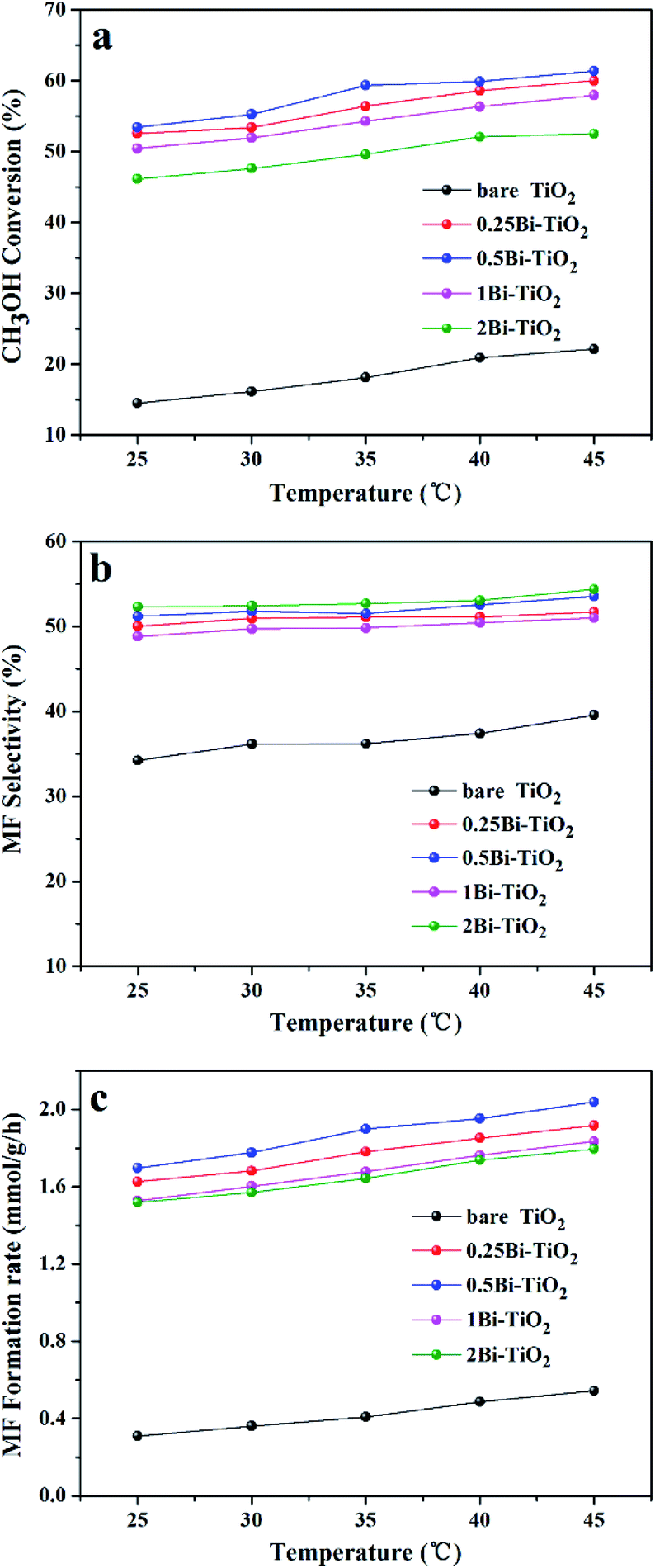
Photocatalytic performance
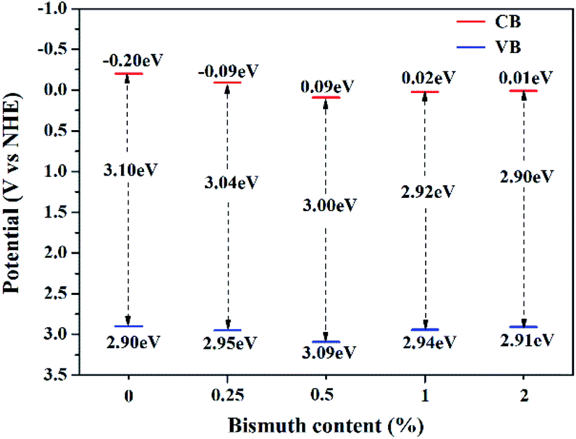
Fig. 9 shows the methanol conversion (Fig. 9a), MF selectivity (Fig. 9b) and MF formation rate (Fig. 9c) of the catalysts for photocatalytic partial oxidation methanol at a temperature range from 25 °C to 45 °C under the irradiation of visible light. The catalysts are not active in the temperature range without irradiation. But temperature exhibits positive effect on methanol conversion, in line with the Arrhenius's rule relating to temperature and reaction rate, under irradiation, suggesting photon provides energy to overcome the barrier in the key step of the reaction and the subsequent steps can occur at low temperatures. The bare TiO2 exhibits very low activity for the reaction. This is because the band gap of this sample is 3.1 eV, corresponding to 400 nm of the absorption wavelength, which just lies on the edge of the visible light spectrum. The Bi-doped samples exhibit far better photocatalytic activity than the bare TiO2. The methanol conversion and MF selectivity of the Bi-doped TiO2 catalyst are all about 50%, while those of the bare TiO2 are less than 20% and 35%, respectively, suggesting the doping of Bi remarkably enhanced the photocatalytic performance. However, the photocatalytic performance of the Bi-doped TiO2 varies with the Bi content in the sample. With the increase of the Bi content, the MF selectivity rises first and then goes down. The 0.5Bi-doped TiO2 exhibits the best MF formation rate. Such a phenomenon has a close relation with the fine band structure of the catalyst, which will be further discussed later. In order to understand the fine band structure of the catalyst, the flat band potentials of the samples were determined by the electrochemical impedance spectra and calculated by the Mott–Schottky plot. Fig. 10 presents typical Mott–Schottky plots constructed from capacitance vs. electrode potential measurements at 0.5 kHz in 0.2 M Na2SO4 solution. All samples show a positive slope in Mott–Schottky plots, which means that they exhibit n-type semiconductor properties.61 The flat band positions of bare TiO2, 0.25Bi-doped TiO2, 0.5Bi-doped TiO2, 1Bi-doped TiO2 and 2Bi-doped TiO2 were 0.40, 0.51, 0.69, 0.62 and 0.61 V vs. RHE, respectively. In general, the conduction band is more negative about −0.1 or −0.2 eV than the flat band for a lot of n-type semiconductor.62 If −0.2 eV is taken, the conduction bands lie on 0.2, 0.31, 0.49, 0.42 and 0.41 V for bare TiO2, 0.25Bi-doped TiO2, 0.5Bi-doped TiO2, 1Bi-doped TiO2 and 2Bi-doped TiO2, respectively. Combining the band gap energy of the samples calculated from the UV-vis investigation, the band energy diagram can be obtained as shown in Fig. 11.
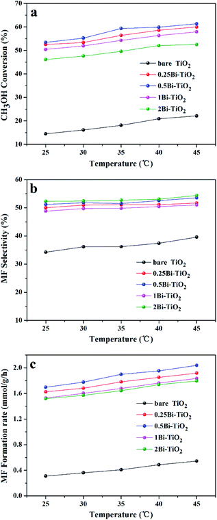 |
| | Fig. 9 Photocatalytic activity of Bi-TiO2 catalysts, (a) methanol conversion; (b) MF selectivity; (c) MF formation rate. | |
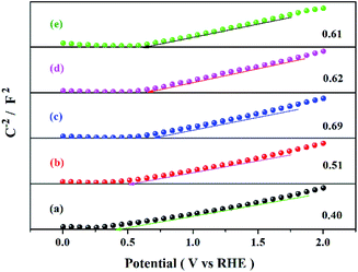 |
| | Fig. 10 Mott–Schottky diagram of the catalyst at 500 Hz in 0.2 M Na2SO4 solution. | |
 |
| | Fig. 11 Band energy diagram of the catalysts with different Bi content. | |
Density functional theory calculations
Bismuth doped titania prepared by the wet chemical method in this study is efficient for photocatalytic partial oxidation of methanol to MF under visible light irradiation. Based on the series characterizations, bismuth species were intercalated in the lattice of anatase. However, it is not yet clear where bismuth exists in the lattice. In order to clarify the possible state of bismuth in the lattice of titania, the DFT method which was implemented in the Cambridge Sequential Total Energy Package (CASTEP) was employed to calculate possible structure, as well as its band structure, density of states and optical properties.63–67 The calculated results indicate that bismuth most possibly occupied the sites of Ti substitutively but not was in the interstitial space of the lattice (see Fig. s3 and s4†). It can be observed in Fig. S3† that the energy levels comprising the valence band and conduction band of Bi-doped TiO2 is more dense than that of pure TiO2, and both the valence band and conduction band move downward, which is consistent with the experimental results (Fig. 11). The band gap of the Bi-doped TiO2 is narrower than that of pure TiO2, which is resulted from the formation of impurity levels between the valence band and conduction of TiO2. Fig. 12 shows the total and fractal state density of pure TiO2 and Bi-doped TiO2. Apparently, the band positions of the Bi-doped TiO2 lowered and new impurity energy levels are formed. The conduction and valence bands of pure TiO2 are mainly composed by the 3d orbitals of Ti and 2p orbitals of O. The 3d orbitals of Ti play a major role in the formation of the conduction band, and the 2p orbitals of O mainly contribute to the formation of the valence band. The 6s and 6p orbitals of Bi involve in the band formation of Bi-doped TiO2, and the 6s orbitals of Bi play the major role in the formation of the impurity level and are responsible for the narrowing of the band gap. The calculated light absorption spectrum is shown in Fig. S4.† An obvious red-shift can be observed in the Bi-doped TiO2, and the absorption band extends to visible light spectrum, which is in line with the experimental results (Fig. 5). By comparison of the calculated and the experimental results, it can be confirmed that Bi species substitute some Ti sites to form Bi doped TiO2.
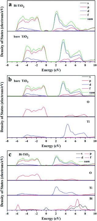 |
| | Fig. 12 Comparison of PDOS, (a) total state density; (b) fractal density of TiO2; (c) fractal density of Bi-TiO2. | |
The Bi content in the catalyst has remarkable impact on the valence band edge (VBE) and surface hydroxyls, and the VBE and the surface hydroxyls exhibit obvious correlation with the photocatalytic performance (Fig. 13). The surface hydroxyls almost show linear relation with the methanol conversion and the VBE exhibits positive correlation with methanol conversion as well. The MF selectivity exhibits remarkable dependence on both the VBE and the surface hydroxyls. The bare TiO2 and 2Bi-TiO2 have similar VBE, and the surface hydroxyls on 2Bi-TiO2 is about 2 times than those on bare TiO2. However, the bare TiO2 exhibits the lowest methanol conversion of 18% and MF selectivity of 36%, while 2Bi-TiO2 exhibits the highest MF selectivity of 53% and relatively high methanol conversion of 50%. The sample 0.25Bi-TiO2 and sample 1Bi-TiO2 have almost equal VBE and similar surface hydroxyls, and they also exhibit similar methanol conversion and MF selectivity. The sample 1Bi-TiO2 has a little more surface hydroxyls than sample 1Bi-TiO2 and the VBE of 1Bi-TiO2 is 0.03 eV higher than that of 2Bi-TiO2, while the MF selectivity of 1Bi-TiO2 is lower than that of 2Bi-TiO2 although the methanol conversion of 1Bi-TiO2 is slightly higher. The sample 0.5Bi-TiO2 has the most surface hydroxyls and VBE, but it exhibits only the highest methanol conversion but moderate MF selectivity. From the above facts, it is definite that the surface hydroxyls play important roles for methanol conversion and MF selectivity. The VBE plays a part role for MF selectivity. Actually, the photocatalytic partial oxidation of methanol to MF must undergo the following important steps.
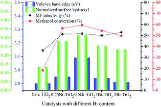 |
| | Fig. 13 VBE, normalized surface hydroxyls as well as methanol conversion and MF selectivity at 35 °C of catalysts with different Bi content. | |
Firstly, methanol molecules react with surface hydroxyls to give rise to methoxy groups. This step can occur at room temperature without irradiation. Secondly, the methoxy groups are oxidized to coordinated formaldehyde by the photoexcited holes. If the redox potential of the hole is higher than that from methoxy to formaldehyde the reaction can occur, or the reaction stops. However, if the redox potential is far higher than required, deep oxidation may occur, resulting in low MF selectivity. Thirdly, the methoxy group reacts with coordinated formaldehyde through coupling reaction to give rise to MF or is deeply oxidized to CO2.68 The surface hydroxyls lost during the reaction can be recovered by oxygen in flow gas filling the oxygen vacancies and combining with hydrogen from methoxy in the second step. Apparently, surface hydroxyls are important intermediate reactant, the more surface hydroxyls the faster the reaction proceeds.49 This is why the methanol conversion is proportional to the surface hydroxyls. The photocatalytic oxidation of methanol can occur on bare TiO2, although it has the lowest VBE, indicating the VBEs of all the Bi-doped catalysts can generate photoexcited holes that enable to oxidize methoxy. The second step and the third step determine the MF selectivity. In order to obtain high MF selectivity, there must be sufficient methoxy groups being able to closely contact with coordinated formaldehyde on the surface of the catalyst. So, over strong redox potential of the holes will result in excess formaldehyde and lean methoxy on the surface of catalyst, and thus low MF selectivity. A moderate redox potential of the photogenerated holes and sufficient surface hydroxyls can maintain reasonable distribution of methoxy groups and coordinated formaldehyde to achieve high methanol conversion and MF selectivity. This is why 2Bi-TiO2 exhibits the highest MF selectivity but the lowest methanol conversion, while 0.5Bi-TiO2 exhibits the high methanol conversion but moderate MF selectivity.
In addition, all of the Bi-doped samples display stronger photocurrent density (see Fig. S6†) than bare TiO2. The 0.5Bi-TiO2 exhibits the best photocurrent, implying the best photo response. With increasing the Bi content, the photocurrent density increases first and then decrease. The worse of photo response for the higher Bi content samples may be resulted from the charge trapping effect.69 The relation between the photocurrent density and irradiation time is in line with valence band edges of the catalysts.
Photocatalytic mechanism
The reaction mechanism of photocatalytic partial oxidation of methanol to MF on Bi-doped TiO2 is similar to those in literature, including the steps mentioned above, except the photoexcited process under visible light irradiation in Bi-doped TiO2. The schematic diagram is shown in Fig. 14. The photons in the band of visible light spectrum is absorbed by electrons in the valence band of Bi-doped TiO2, and the electrons are excited to the conduction band via the impurity level, mainly composed by the 6s orbitals of Bi. The conduction band is mainly composed by the O 2p orbitals and a small part of Ti 3d and Bi 6p orbitals. The overcharged surface can adsorb and dissociate oxygen molecules into active oxygen atoms to fill the surface oxygen vacancies resulted from the loss of surface hydroxyls during the reaction. Besides, H from the methanol or methoxy can react with hydroxyl to form water, in the case of lean methoxy on the surface of catalyst, the coordinated formaldehyde can be further oxidized to CO2 and water.
 |
| | Fig. 14 Reaction mechanism of selective oxidation of methanol to methyl formate with Bi-TiO2 catalyst under simulated sunlight. | |
Conclusions
A series of Bi-TiO2 catalysts were prepared by wet chemical method. The catalysts exhibit visible light photoactive to partial oxidation of methanol to MF. Bismuth is intercalated in the lattice of anatase by substitution of titanium. Impurity levels are formed in the valence band, conduction band as well as between the two bands. The Bi 6s and 5p orbitals contribute to the formation of the impurity levels. The Bi doped TiO2 enhances the surface hydroxyls, reduces the band gaps and raises the VBEs. The reduced band gap makes the catalyst respond to visible light. The surface hydroxyls are beneficial to the methanol conversion, and the rise of VBE enhances the redox potential of the photogenerated holes. Only moderate redox potentials and sufficient surface hydroxyls can result in high methanol conversion and MF selectivity.
Conflicts of interest
There are no conflicts to declare.
Acknowledgements
This project was funded by the National Science Foundation of China (No. 21766020, No. 21566026), the Natural Science Foundation of Inner Mongolia (No. 2019MS02011), the continuously supporting project of Grassland Talent of Inner Mongolia and the major basic research and open project of the Inner Mongolia Autonomous Region (30500-515330303).
Notes and references
- S. P. Tonner, D. L. Trimm, M. S. Wainwright and N. W. Cant, Ind. Eng. Chem. Prod. Res. Dev., 1984, 23, 384–388 CrossRef.
- E. Tronconi, A. S. Elmi, N. Ferlazzo, P. Forzatti, G. Busca and P. Tittarelli, Ind. Eng. Chem. Res., 1987, 26, 1269–1275 CrossRef CAS.
- A. S. Elmi, E. Tronconi, C. Cristiani, J. P. Gomez Martin, P. Forzatti and G. Busca, Ind. Eng. Chem. Res., 1989, 28, 387–393 CrossRef CAS.
- P. J. A. Tijm, F. J. Waller and D. M. Brown, Appl. Catal., A, 2001, 221, 275–282 CrossRef CAS.
- J. S. Lee, J. C. Kim and Y. G. Kim, Appl. Catal., 1990, 57, 1–30 CrossRef CAS.
- L. Rong, Z. Xu, J. Sun and G. Guo, J. Energy Chem., 2018, 27, 238–242 CrossRef.
- C. Han, X. Yang, G. Gao, J. Wang, H. Lu, J. Liu, M. Tong and X. Liang, Green Chem., 2014, 16, 3603–3615 RSC.
- J. Liu, C. Han, X. Yang, G. Gao, Q. Shi, M. Tong, X. Liang and C. Li, J. Catal., 2016, 333, 162–170 CrossRef CAS.
- X. Yang, A. Zhang, G. Gao, D. Han, C. Han, J. Wang, H. Lu, J. Liu and M. Tong, Catal. Commun., 2014, 43, 192–196 CrossRef CAS.
- J. C. Colmenares, P. Lisowski, D. Łomot, O. Chernyayeva and D. Lisovytskiy, Chemsuschem, 2015, 8, 1676–1685 CrossRef CAS.
- H. Kominami, H. Sugahara and K. Hashimoto, Catal. Commun., 2010, 11, 426–429 CrossRef CAS.
- C. Li, X. Yang, G. Gao, Y. Li, W. Zhang, X. Chen, H. Su, S. Wang and Z. Wang, Catal. Sci. Technol., 2019, 9, 6240–6252 RSC.
- Y. C. Pu, G. Wang, K. D. Chang, Y. Ling, Y. K. Lin, B. C. Fitzmorris, C. M. Liu, X. Lu, Y. Tong, J. Z. Zhang, Y. J. Hsu and Y. Li, Nano Lett., 2013, 13, 3817–3823 CrossRef CAS.
- Y. C. Pu, Y. Ling, K. D. Chang, C. M. Liu and Y. Li, J. Phys. Chem. C, 2014, 118, 15086–15094 CrossRef CAS.
- Y.-H. Chiu and Y.-J. Hsu, Nano Energy, 2017, 31, 286–295 CrossRef CAS.
- Y. H. Chiu, T. H. Lai, C. Y. Chen, P. Y. Hsieh, K. Ozasa, M. Niinomi, K. Okada, T. M. Chang, N. Matsushita, M. Sone and Y. J. Hsu, ACS Appl. Mater. Interfaces, 2018, 10, 22997–23008 CrossRef CAS PubMed.
- J.-M. Li, C.-W. Tsao, M.-J. Fang, C.-C. Chen, C.-W. Liu and Y.-J. Hsu, ACS Appl. Nano Mater., 2018, 1, 6843–6853 CrossRef CAS.
- Y.-H. Chiu, T.-F. M. Chang, C.-Y. Chen, M. Sone and Y.-J. Hsu, Catalysts, 2019, 9, 430–462 CrossRef CAS.
- P. Y. Hsieh, Y. H. Chiu, T. H. Lai, M. J. Fang, Y. T. Wang and Y. J. Hsu, ACS Appl. Mater. Interfaces, 2019, 11, 3006–3015 CrossRef CAS PubMed.
- M.-J. Fang, C.-W. Tsao and Y.-J. Hsu, J. Phys. D: Appl. Phys., 2020, 53(14), 143001 CrossRef CAS.
- P.-Y. Hsieh, J.-Y. Wu, T.-F. M. Chang, C.-Y. Chen, M. Sone and Y.-J. Hsu, Arabian J. Chem., 2020 DOI:10.1016/j.arabjc.2020.05.025.
- J. Cunninghamand and B. K. Hodnett, J. Chem. Soc., Faraday Trans., 1981, 77, 2777–2801 RSC.
- Y. C. Liu, G. L. Griffin, S. S. Chan and I. E. Wachs, J. Catal., 1985, 94, 108–119 CrossRef CAS.
- P. Lisowski, J. C. Colmenares, D. Łomot, O. Chernyayeva and D. Lisovytskiy, J. Mol. Catal. A: Chem., 2016, 411, 247–256 CrossRef CAS.
- G. Ramis, G. Busca and V. Lorenzelli, J. Chem. Soc. , Faraday Trans., 1987, 183, 1591–1599 RSC.
- A. Fujishima and K. Honda, Nature, 1972, 238, 37–38 CrossRef CAS PubMed.
- U. Alam, M. Fleisch, I. Kretschmer, D. Bahnemann and M. Muneer, Appl. Catal., B, 2017, 218, 758–769 CrossRef CAS.
- R. Asahi, T. Morikawa, T. Ohwaki, K. Aoki and Y. Taga, Science, 2001, 293, 269–271 CrossRef CAS PubMed.
- Y. Hu, Y. Cao, P. Wang, D. Li, W. Chen, Y. He, X. Fu, Y. Shao and Y. Zheng, Appl. Catal., B, 2012, 125, 294–303 CrossRef CAS.
- Y. Huang, J.-J. Cao, F. Kang, S.-J. You, C.-W. Chang and Y.-F. Wang, Aerosol Air Qual. Res., 2017, 17, 2555–2565 CrossRef CAS.
- L. Kumaresan, A. Prabhu, M. Palanichamy, E. Arumugam and V. Murugesan, J. Hazard. Mater., 2011, 186, 1183–1192 CrossRef CAS PubMed.
- M. Schraml-Marth, A. Wokaun and A. Baiker, J. Catal., 1990, 124, 86–96 CrossRef CAS.
- A. Khaleel, M. Meetani, N. S. Al Kaabi, K. Abdul al, S. Salem, S. Mansour, S. H. Ahmed, M. Bakiro, T. Ramachandran, F. Hamed and A. Alzamly, J. Water Reuse Desalin., 2019, 9, 31–46 CrossRef.
- P. A. K. Reddy, B. Srinivas, P. Kala, V. D. Kumari and M. Subrahmanyam, Mater. Res. Bull., 2011, 46, 1766–1771 CrossRef CAS.
- S. Sood, S. K. Mehta, A. Umar and S. K. Kansal, New J. Chem., 2014, 38, 3127–3136 RSC.
- S. Sajjad, S. A. Leghari, F. Chen and J. Zhang, Chem.–Eur. J., 2010, 16, 13795–13804 CrossRef CAS PubMed.
- P. Magesan, P. Ganesan and M. J. Umapathy, Optik, 2016, 16, 5171–5180 CrossRef.
- G. D. Bhowmick, M. T. Noori, I. Das, B. Neethu, M. M. Ghangrekar and A. Mitra, Int. J. Hydrogen Energy, 2018, 43, 7501–7510 CrossRef CAS.
- T. Ohsaka, F. Izumi and Y. Fujiki, J. Raman Spectrosc., 1978, 7, 321–324 CrossRef.
- W. Zhao, X. Wang, H. Sang and K. Wang, Chin. J. Chem., 2013, 31, 415–420 CrossRef CAS.
- R. López and R. Gómez, J. Sol-Gel Sci. Technol., 2011, 61, 1–7 CrossRef.
- S. Murcia-López, M. C. Hidalgo and J. A. Navío, Appl. Catal., A, 2011, 404, 59–67 Search PubMed.
- K. S. W. Sing, Pure Appl. Chem., 1982, 54, 2201–2218 Search PubMed.
- S. W. K. Sing, Pure Appl. Chem., 1985, 57, 603–619 Search PubMed.
- C. Y. Yen, Y. F. Lin, C. H. Hung, Y. H. Tseng, C. C. Ma, M. C. Chang and H. Shao, Nanotechnology, 2008, 19, 045604 CrossRef PubMed.
- H. Zuo, J. Sun, K. Deng, R. Su, F. Wei and D. Wang, Chem. Eng. Technol., 2007, 30, 577–582 CrossRef CAS.
- C. P. Sibu, S. R. Kumar, P. Mukundan and K. G. K. Warrier, Chem. Mater., 2002, 14, 2876–2881 CrossRef CAS.
- V. Augugliaro, S. Coluccia, V. Loddo, L. Marchese and M. Schiavello, Appl. Catal., B, 1999, 20, 15–27 CrossRef CAS.
- K. L. Yeung, S. T. Yau, A. J. Maira, J. M. Coronado, J. Soria and P. L. Yue, J. Catal., 2003, 20, 107–116 CrossRef.
- D. O. Scanlon, C. W. Dunnill, J. Buckeridge, S. A. Shevlin, A. J. Logsdail, S. M. Woodley, C. R. Catlow, M. J. Powell, R. G. Palgrave, I. P. Parkin, G. W. Watson, T. W. Keal, P. Sherwood, A. Walsh and A. A. Sokol, Nat. Mater., 2013, 12, 798–801 CrossRef CAS.
- A. Sanchez-Martinez, O. Ceballos-Sanchez, C. Koop-Santa, E. R. López-Mena, E. Orozco-Guareño and M. García-Guaderrama, Ceram. Int., 2018, 44, 5273–5283 CrossRef CAS.
- H. Li, D. Wang, P. Wang, H. Fan and T. Xie, Chem.–Eur. J., 2009, 15, 12521–12527 CrossRef CAS PubMed.
- D. Chen, D. Yang, Q. Wang and Z. Jiang, Ind. Eng. Chem. Res., 2006, 45, 4110–4116 CrossRef CAS.
- Z. Zhang, J. Long, X. Xie, H. Zhuang, Y. Zhou, H. Lin, R. Yuan, W. Dai, Z. Ding, X. Wang and X. Fu, Appl. Catal., A, 2012, 425–426, 117–124 CrossRef CAS.
- A. Naldoni, M. Allieta, S. Santangelo, M. Marelli, F. Fabbri, S. Cappelli, C. L. Bianchi, R. Psaro and V. Dal Santo, J. Am. Chem. Soc., 2012, 134, 7600–7603 CrossRef CAS PubMed.
- T. K. Sham and M. S. Lazarus, Chem. Phys. Lett., 1979, 68, 426–432 CrossRef CAS.
- J. Ma, J. Chu, L. Qiang and J. Xue, RSC Adv., 2012, 2, 3753–3758 RSC.
- W. Yuqi, L. Gongxuan and L. Shuben, J. Phys. Chem. C, 2009, 2, 9950–9955 Search PubMed.
- M. Kang, Y.-R. Ko, M.-K. Jeon, S.-C. Lee, S.-J. Choung, J.-Y. Park, S. Kim and S.-H. Choi, J. Photochem. Photobiol., A, 2005, 173, 128–136 CrossRef CAS.
- Y. Xie, C. Zhang, D. Wang, J. Lu, Y. Wang, J. Wang, L. Zhang and R. Zhang, New J. Chem., 2019, 43, 15368–15374 RSC.
- S. B. Taieb, I. B. Assaker, A. Bardaoui, M. Gannouni, A. Souissi, S. Nowak, L. Mouton, S. Ammar and R. Chtourou, Int. J. Hydrogen Energy, 2016, 41, 6230–6239 CrossRef CAS.
- L. Li, J. Yan, T. Wang, Z. J. Zhao, J. Zhang, J. Gong and N. Guan, Nat. Commun., 2015, 6, 5881 CrossRef PubMed.
- V. Milman, K. Refson, S. J. Clark, C. J. Pickard, J. R. Yates, S. P. Gao, P. J. Hasnip, M. I. J. Probert, A. Perlov and M. D. Segall, J. Mol. Struct.: THEOCHEM, 2010, 954, 22–35 CrossRef CAS.
- S. J. Clark, M. D. Segall, C. J. Pickardii, P. J. Hasnipiii and M. I. J. Probertiv, Z. Kristallogr., 2005, 220, 567–570 CAS.
- J. E. Jaffe, Z. Lin and A. C. Hess, Phys. Rev. B, 1998, 57, 11834–11837 CrossRef CAS.
- K. Choudhary and F. Tavazza, Comput. Mater. Sci., 2019, 161, 300–308 CrossRef CAS PubMed.
- C. Di Valentin, E. Finazzi, G. Pacchioni, A. Selloni and E. Giamello, Chem. Mater., 2008, 20, 3706–3714 CrossRef CAS.
- K. R. Phillips, S. C. Jensen, M. Baron, S. C. Li and C. M. Friend, J. Am. Chem. Soc., 2013, 135, 574–577 CrossRef CAS PubMed.
- Y. H. Lu, W. H. Lin, C. Y. Yang, Y. H. Chiu, Y. C. Pu, M. H. Lee, Y. C. Tseng and Y. J. Hsu, Nanoscale, 2014, 6, 8796–8803 RSC.
Footnote |
| † Electronic supplementary information (ESI) available. See DOI: 10.1039/d0ra06309f |
|
| This journal is © The Royal Society of Chemistry 2020 |
Click here to see how this site uses Cookies. View our privacy policy here. 
 Open Access Article
 This Open Access Article is licensed under a Creative Commons Attribution-Non Commercial 3.0 Unported Licence
 *,
Guanjun Gao,
Zhe Yan,
Haiquan Su
*,
Guanjun Gao,
Zhe Yan,
Haiquan Su