 Open Access Article
Hydrophilic modification of polyvinyl chloride with polyacrylic acid using ATRP†
Edina Rusena,
Raluca Şomoghib,
Cristina Busuioca and
Aurel Diacon *a
*a
aUniversity POLITEHNICA of Bucharest, Faculty of Applied Chemistry and Materials Science, Gh. Polizu Street 1-7, Bucharest, 011061, Romania. E-mail: aurel_diacon@yahoo.com; aurel.diacon@upb.ro
bNational Research and Development Institute for Chemistry and Petrochemistry – ICECHIM, 202 Splaiul Independenţei, Bucharest, 060021, Romania
First published on 28th September 2020
Abstract
The aim of this paper was the synthesis of amphiphilic copolymers by employing an atom transfer radical polymerization (ATRP), control polymerization “grafting from” method, initiated both on the surface of an iodinated polyvinyl chloride (PVC–I) membrane and in solution. The iodination of PVC was performed through a Conant-Finkelstein reaction that afforded a 30% molar transformation. Using the contact angle measurements, we highlighted the higher degree of grafting polyacrylic acid (PAA) in the case of solution polymerization, the polar fraction increasing significantly. The micromembrane obtained by surface grafting has pores with a homogenous distribution, which contain –COOH functional groups and with a pore size that decreased about 10 times compared to the initial membrane. The TGA analysis highlighted the thermal resistance changes that the polymers registered.
1. Introduction
Polyvinyl chloride (PVC) is the third most commonly produced plastic in the world, exceeded only by polyethylene and polypropylene.1,2 It is supplied commercially in a variety of formulations, usually as a white powder or colorless granules. The polymer is resistant to moisture, weathering, most acids, fats and oils, many organic solvents, and attack by fungi. It is easily colored and manufactured in a variety of forms, including sheets, films, fibers, and foam. A wide range of applications including building materials, electrical wire and cable, leather seats, industrial components, and packaging products involve the use of PVC based materials.2 The chemical modification of polymers opens a myriad of applications for the functionalized polymers that acquire the reactivity and some of the characteristics of the introduced functionality while keeping the main features of the base polymeric matrix.3–7 Therefore, many functional polymers have been prepared through the reaction of different chemically reactive species with a base polymer.A substantial improvement of interfacial compatibility between PVC and liquid media (hydrophilic or hydrophobic) can be achieved by different surface treatments.8–11 Surface modified PVC has been used especially in the biomedical field,12 where one key parameter is the interface interaction between the polymer and the biological liquids is critical for a successful application. Another important field of application for PVC is the fabrication of membranes13 for different types of applications, where surface treatment of the polymer can extend the lifetime of the product and alter significantly its characteristics.14 PVC with different surface treatments or modifications has found significant application also in electronics.15–17 These numerous applications highlight the implication of polymer surface functionality characteristics and the practical importance of amphiphilic copolymers.18–20
The grafting process approach represents an efficient method for polymer properties modification.21–23 Thus far, the grafting process has been achieved mainly by three processes:24 “grafting onto”, “grafting from” and “grafting through” affording different polymer architectures such as comb- or brush-type graft copolymers. One of the more intense used methods allowing the use of controlled polymerization techniques is the “grafting from” method.25 This method can be employed usually in two types of processes: surface grafting and graft copolymerization. The surface grafting approach implies that only the surface is modified, without changing the properties of the bulk. Surface graft polymerization has been used to modify membrane surfaces, using various surface activation methods such as photo-activation,26 plasma treatment,27 ozone treatment,28 and chemical initiator,29 which can proceed via either free radical graft polymerization or living graft polymerization. Graft copolymerization3,7,30–32 involves the reaction of preformed homopolymer or copolymer with fresh monomers that are then covalently bonded onto the polymer chains, therefore conventional polymerization methods can be applied.
PVC modification through the grafting of acrylic acid represents an efficient route for materials properties enhancement, especially when considering membrane technologies or biomedical applications.33–37 PVC - acrylic acid grafting can be achieved by different routes such as plasma or electron beam facilitated grafting of poly(acrylic acid),14,27,33,35,38 photoinduced radical polymerization,39 use of chemically induced physisorbed radical species,36,40 in situ chlorinating graft copolymerization41 and controlled polymerization reactions. However, in the case of controlled polymerization techniques for the fabrication of polyacrylic acid grafts, the carboxyl functionality is usually obtained using a post-polymerization hydrolysis stage.42,43
Atom Transfer Radical Polymerization (ATRP) is a versatile technique that allows achieving a controlled radical polymerization involving a solubilized initiator, as well as a surface-initiated polymerization process.43 This advantage justifies the wide use of the technique that involves a fast–dynamic equilibrium between dormant species and active radical species to provide control of the polymerization (Scheme 1). The synthesis of amphiphilic block-copolymers has attracted a lot of interest due to the multitude of possible applications44,45 given by the tailorable hydrophilic/hydrophobic and their self-assembly properties.46
This study deals with the synthesis of amphiphilic copolymers presenting as the main chain PVC and polyacrylic acid grafts (PAA). The synthesis strategy pursued involved the ATRP grafting technique of acrylic acid (AA) monomer from the PVC backbone previously modified by iodination (PVC–I). The PVC iodination was performed, due to the greater lability of the C–I bond, compared to the C–Cl bond, thus assuring an efficient initiation process. The novelty of this study resides in the employing of the ATRP ‘’grafting from’’ technique in the solution for the generation of amphiphilic copolymers and the surface modification of a PVC–I membrane (Scheme 2) using directly the acrylic acid as a monomer and in the characterization of the materials properties obtained through this route. The obtained materials were assessed in terms of contact angle and surface tension properties, self-assembly properties, morphology and thermal resistance modification.
2. Materials and methods
2.1. Materials
Poly(vinyl chloride) (PVC) (OLTCHIM), obtained by suspension polymerization, elemental analysis (0% N, 39.36% C, 4.83% H, 55.81% Cl), (grains); d = 0.063–0.09 mm, sodium iodide (NaI) (Aldrich), acetone, (A) (Chimopar), tetrahydrofuran (THF) (Aldrich), methanol (M) (Aldrich), cyclohexanone (Aldrich), hexane (Aldrich), bipyridyl (BiPy) (Merck), N,N,N′,N′,N′′-penta-methyldiethylenetriamine (PMDTA), CuBr (Aldrich), ethylene glycol (Chimopar) (EG), CH2I2 (Aldrich) (DIM) were used without any prior purification. Acrylic acid (AA) (Merck) was purified by vacuum distillation.2.2. Methods
![[thin space (1/6-em)]](https://www.rsc.org/images/entities/char_2009.gif) :
:![[thin space (1/6-em)]](https://www.rsc.org/images/entities/char_2009.gif) acetone mixture (1
acetone mixture (1![[thin space (1/6-em)]](https://www.rsc.org/images/entities/char_2009.gif) :
:![[thin space (1/6-em)]](https://www.rsc.org/images/entities/char_2009.gif) 2 (vol
2 (vol![[thin space (1/6-em)]](https://www.rsc.org/images/entities/char_2009.gif) :
:![[thin space (1/6-em)]](https://www.rsc.org/images/entities/char_2009.gif) vol)) and 24 g of NaI were added to this solution. Then, the reaction was stirred under nitrogen at 40 °C for 24 h. After completing the reaction time, the modified polymer, PVC–I, was precipitated in a mixture of methanol
vol)) and 24 g of NaI were added to this solution. Then, the reaction was stirred under nitrogen at 40 °C for 24 h. After completing the reaction time, the modified polymer, PVC–I, was precipitated in a mixture of methanol![[thin space (1/6-em)]](https://www.rsc.org/images/entities/char_2009.gif) :
:![[thin space (1/6-em)]](https://www.rsc.org/images/entities/char_2009.gif) distilled water=(2
distilled water=(2![[thin space (1/6-em)]](https://www.rsc.org/images/entities/char_2009.gif) :
:![[thin space (1/6-em)]](https://www.rsc.org/images/entities/char_2009.gif) 1 (vol
1 (vol![[thin space (1/6-em)]](https://www.rsc.org/images/entities/char_2009.gif) :
:![[thin space (1/6-em)]](https://www.rsc.org/images/entities/char_2009.gif) vol)), (light-yellow powder) separated and dried under vacuum until a constant mass was attained.
vol)), (light-yellow powder) separated and dried under vacuum until a constant mass was attained.2.3. Characterization
The molecular weights of the obtained polymers were analyzed using PL-GPC 50 Integrated GPC/SEC System (Agilent Technologies) using a 1 mL min−1 THF flow rate and a column oven temperature of 30 °C using polystyrene as a standard. The GPC traces were treated according to Gavrilov et al.48A KSV CAM 200 apparatus was used for static contact angle measurements performed on dried films. Different liquids droplets were used with a drop volume of 20 μL. The measurement of each contact angle was made within 10 s after each drop to ensure that the droplet did not soak into the film. The contact angles reported were the mean of 10 determinations.
The morphology of polymer films was investigated by optical microscopy using an Olympus BX41 light microscope (Japan) equipped with live view E330 7.5MP Digital SLR Camera and QuickPhoto Micro 2.3 software. The images were collected in transmission mode.
The chemical bonds and groups were studied by Fourier transform infrared (FTIR) spectroscopy, with a Thermo Scientific Nicolet 6700 spectrophotometer, the wavenumber ranging between 400 and 4000 cm−1.
The morphology was also examined by scanning electron microscopy (SEM), employing a Quanta Inspect F50 microscope equipped with an energy-dispersive X-ray spectroscopy (EDX) probe; the accelerating voltage was set at 30 kV.
The morphology of the polymer films was evaluated using transmission electron microscopy (TEM) (Tecnai G2 F20 TWIN Cryo-TEM, FEI Company), at 300 kV acceleration voltage, at a 1 Å resolution. A small drop polymer solution (in THF), was put on a carbon film copper grid, dried at ambient temperature and then, visualized on TEM.
The thermogravimetric analysis (TGA) was performed using a Netzsch TG 209 F3 Tarsus equipment considering the next parameters: nitrogen atmosphere flow rate 20 mL min−1; samples mass: ∼2 mg; temperature range: room temperature −900 °C; heating rate: 10°C min−1 in a platinum crucible.
3. Results and discussion
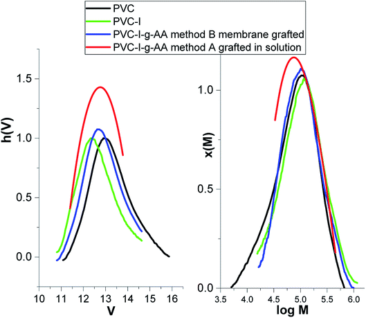
The first stage of the study consisted in the determination of the degree of modification/iodation of the PVC polymer as result of the Finkelstein reaction.5,47 The large difference between the atomic mass of the halides (Cl and I) makes this determination facile. Thus, according to the GPC data (Fig. 1) the molecular weight increased from 52![[thin space (1/6-em)]](https://www.rsc.org/images/entities/char_2009.gif) 000 g mol−1 (Mn –PVC) to 77
000 g mol−1 (Mn –PVC) to 77![[thin space (1/6-em)]](https://www.rsc.org/images/entities/char_2009.gif) 400 g mol−1 (Mn–PVC–I), the polydispersity index remained almost unchanged (2.25 to 2.07) and the degree of iodination can be estimated to be about 30% molar.
400 g mol−1 (Mn–PVC–I), the polydispersity index remained almost unchanged (2.25 to 2.07) and the degree of iodination can be estimated to be about 30% molar.
The two synthesis strategies that have been employed consisted in: (A) AA grafting from PVC-I using an ATRP process in solution, in a homogenous media and (B) grafting of AA from the surface of a preformed PVC–I membrane using ATRP (Scheme 2). For both methods the same PVC–I starting material was used. Also, both methods take advantage on the iodine capacity to efficiently initiate an ATRP process.
Method (A) – in solution represents the straightforward and easier approach, but due to hydrophilic characteristics of the PAA grafts is difficult to find a common solvent–nonsolvent system, in the event of the formation of a subsequent membrane by the inverse-phase method. It is this behavior that first of all supports the (B) strategy – the surface-initiated polymerization using the preformed membrane resulting in a grafting-from technique for generation of PAA grafts.
In order to confirm the PAA grafting on the PVC–I chain, we performed FT-IR analysis. Thus, a carboxylic acid shows an absorption pattern in the region 3125 cm−1, with the broad O–H band superimposed on the sharp C–H stretching bands. The specific signal for carbonyl C![[double bond, length as m-dash]](https://www.rsc.org/images/entities/char_e001.gif) O stretching corresponding to the carboxylic acid appears as an intense band from 1730 cm−1. The FTIR spectrum of the PVC includes C–Cl stretching at 700 cm−1, C–C stretching at 1100 cm−1, C–H stretching of CH–Cl (2968, 2917, and 2845 cm−1), CH2 wagging (1425, 1330 and 1250 cm−1), CH2 rocking at 960 cm−1. In the case of PVC-I, the C–I stretching appears at 635 cm−1.
O stretching corresponding to the carboxylic acid appears as an intense band from 1730 cm−1. The FTIR spectrum of the PVC includes C–Cl stretching at 700 cm−1, C–C stretching at 1100 cm−1, C–H stretching of CH–Cl (2968, 2917, and 2845 cm−1), CH2 wagging (1425, 1330 and 1250 cm−1), CH2 rocking at 960 cm−1. In the case of PVC-I, the C–I stretching appears at 635 cm−1.
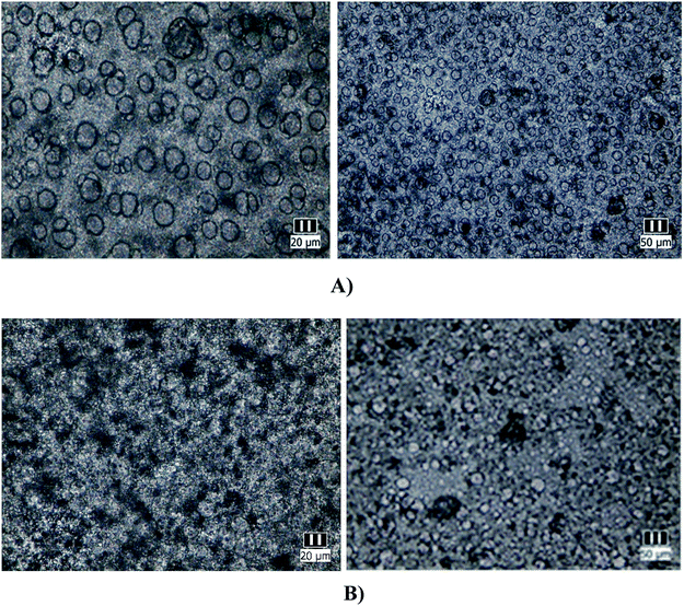
Optical microscopy was employed as a preliminary characterization of the grafted copolymers since it can give information about the morphology of the copolymers and their amphiphilic characteristics.3,49 Both synthesized materials, the polymer obtained by ATRP polymerization in solution and the modified membrane by surface-initiated grafting were solubilized in THF (20% by mass), deposited glass plates and allowed to slowly dry. The obtained images are presented in Fig. 2(A and B).
From Fig. 2, it is easy to notice that nearly monodisperse spherical micelles are formed with dimensions between 10–20 μm. The micelles are regarded as colloidal particles with nearly pure PAA core and THF-swollen PVC corona domains. Thus, the grafted copolymers can be envisaged for possible practical applications, such as: emulsifiers, surface-modifying agents, coating materials and compatibilizers in polymer blends.18,19
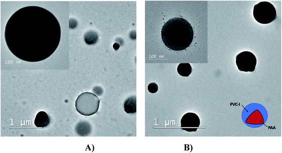
The spherulite structuring of the PVC–I–g-PAA grafts was also confirmed by TEM analysis (Fig. 3) with a larger size in the case of PVC–I–g-PAA (A).
Being an amphiphilic copolymer, the next step consisted in determining the surface energy, the polar components, respectively dispersive components.
Surface energy with its dispersive and polar components for the solid surfaces was estimated using the Owens–Wendt model.50–53 With the known surface energy components of liquids and by measuring the contact angle on a flat surface, the surface energy components of solid substrates can be calculated, as shown in eqn (1)–(4).50–53 For the calculation, contact angles of water (WA), ethylene glycol (EG) and diiodomethane (DIM) were measured on flat film surfaces (Table 1).
| Sample | WA (°) | EG (°) | DIM (°) |
|---|---|---|---|
| PVC | 89 ± 0.58 | 60 ± 0.55 | 39.62 ± 0.21 |
| PVC–I | 76 ± 0.66 | 55 ± 0.60 | 67.33 ± 0.46 |
| PVC–I–g-PAA (A) | 10 ± 0.23 | 56 ± 0.30 | 49 ± 0.70 |
| PVC–I–g-PAA (B) | 45 ± 0.44 | 82 ± 0.70 | 69 ± 0.30 |
The dispersive and polar constants for the three liquids are: (Table 2)
The equations used are:
 | (1) |
γS = γSL + γL![[thin space (1/6-em)]](https://www.rsc.org/images/entities/char_2009.gif) cos cos![[thin space (1/6-em)]](https://www.rsc.org/images/entities/char_2009.gif) θ θ
| (2) |
 | (3) |
| γS = γdS+γpS | (4) |
• θ: contact angle of liquid on solid surface
• γSL: interfacial energy between solid and liquid
• γS: surface energy of solid
• γdS: dispersive component surface energy of solid
• γpS: polar component surface energy of solid
• γL: surface energy of liquid
• γdL: dispersive component surface energy of liquid
• γpL: polar component surface energy of liquid
Owens–Wendt theory (extended Fowkes) extends on the Fowkes model by incorporating Good's equation:
 | (5) |
 | (6) |
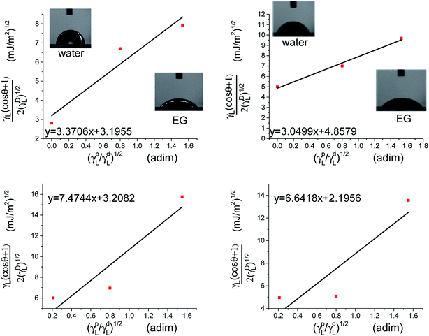
The polar and dispersive components of the liquid surface energy are known and plotting the left side of eqn (6) against (γpL)1/2/(γdL)1/2 will produce a linear line of data points. Linear regression of data will allow for determination of γpS as the square of the slope and γdS as the square of the y-intercept (Fig. 4).
Following the graphical approximation in Fig. 4, the next values were obtained.
• PVC: γpS=11.35 mJ m−2, γdS = 10.21 mJ m−2, polar fraction xpS = 0.52.
• PVC–I: γpS = 9.24 mJ m−2, γdS = 23.52 mJ m−2, polar fraction xpS = 0.28.
• PVC–I–g-PAA (A): γpS = 55.80 mJ m−2, γdS = 10.24 mJ m−2, polar fraction xpS = 0.85.
• PVC–I–g-PAA (B): γpS = 44.08 mJ m−2, γdS = 48.87 mJ m−2, polar fraction xpS = 0.90.
The grafting of PAA leads to an increase of the polar fraction, nevertheless, the copolymers obtained by method (A) have a polar fraction 1.3 times higher compared to the polymer obtained by method (B). This result can be explained by the higher degree of grafting in solution compared to the degree of grafting from the surface-initiated polymerization. Considering the molecular weight of the backbone and of the grafts, a grafting degree was calculated for each method (see ESI†). As expected, the grafting degree in solution (method A 33%) was higher than the grafting from the membrane surface (27%) which can be explained by the high.
The prospect to obtain a micromembrane by synthesis is very attractive but also necessary since it is difficult to select a common solvent–nonsolvent system for both polymers that are present in the main chain and the grafts.
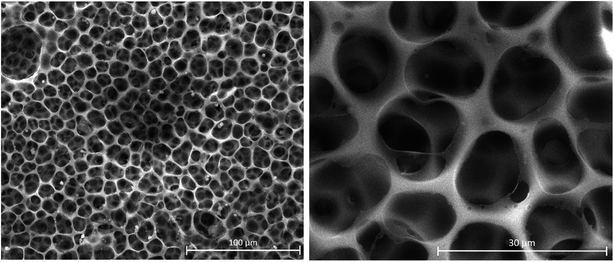
To ascertain the morphological changes for the membrane as a result of the PAA grafting reaction, we have characterized by SEM the initial PVC-I membrane (Fig. 5).
The analysis of the images in Fig. 5 confirms a good dimensional homogeneity and uniform distribution of the pores, which have a diameter of around 15 μm.
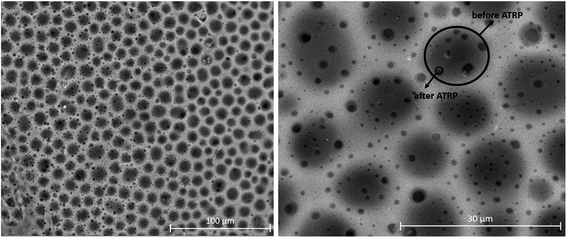
The next step was the investigation by SEM of the membrane after the PAA ‘’grafting from’’ its surface. As it can be observed in Fig. 6, the pore homogeneity was preserved, but there is a clear reduction of the pore diameter due to the PAA grafts to a value of around 1.5 μm. On one side of the membrane surface, the pores seem connected by PAA grafts, resulting in the formation of an increased number of smaller pores, a result similar to other literature examples.54,55 However, the initial porous and canal structure it is clearly visible. On average, the pore size decrease by a factor of 10.
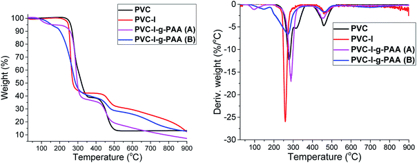
The thermogravimetric analysis (TGA) gives important information about the thermal stability of the synthesized materials and that can be correlated with their composition. Thus, in Fig. 7 are presented the thermal degradation profiles and derivative thermogravimetric analyses (DTG) of the samples.
The TGA and DTG analysis presented in Fig. 7 reveals a two-stage degradation process with the first (about 220–370 °C) corresponding to the dechlorination of PVC, with formation and stoichiometric elimination of hydrochloric acid and chlorinated hydrocarbon.56 The formation of aromatic compounds by the cyclization of conjugated polyene57 mainly occurred in the second stage (about 350–450 °C). In the last stage (>450 °C), the second degradation was shown, which is mainly contributed to the degradation of the complex structures resulting from aromatization.58
In the case of PVC–I the thermal degradation curve has a similar aspect to PVC but it starts at a lower temperature since the C–I bond is more labile compared to C–Cl. In the case of PVC–I–g-PAA (A) and PVC–I–g-PAA (B) the first stage of decomposition is up to 150 °C and represents the loss of water molecules, with the formation of cyclic structures,59 followed by the decarboxylation stage 150–270 °C and then the third stage is the decomposition of the polymer chain. Comparing the grafting methods (A) and (B) TGA results, it is clearly visible a lower weight loss in the case of (B) that is determined by a lower degree of PAA grafting.
4. Conclusions
The present paper presents the synthesis of an amphiphilic grafted copolymer containing PVC (main chain) and PAA grafts using and iodinated PVC as starting material. The two methods of synthesis were: (A) grafting from PVC–I in solution and (B) surface-initiated polymerization using a PVC–I membrane. Both methods allow access to amphiphilic copolymers, characterized by optical microscopy, contact angle measurements-surface energy calculation, SEM and TGA analyses. From the calculation results for PVC–I and PVC, it can be noticed, that the polar component increased 5 times, due to higher hydrophilicity and wettability with polar liquids. Comparing the two specimens (A) solution and (B) membrane, the polarity in case (A) is clearly superior, due to the higher degree of grafting. Using the ATRP “grafting from” technique, a micromembrane was obtained with homogeneous distributed pores, which contain –COOH functional groups. The morphology changes in the membrane structure were evaluated by SEM and TGA analysis confirmed the changes in the polymer structures.Conflicts of interest
There are no conflicts to declare.Acknowledgements
The authors would like to thank for financial support from University Politehnica of Bucharest, through the PubArt - Program for supporting publication of articles and scientific communications. Aurel Diacon acknowledges the financial support received from the Competitiveness Operational Programme 2014–2020, Action 1.1.4: Attracting high-level personnel from abroad in order to enhance the RD capacity, project: P_37_471, „Ultrasonic/Microwave Nonconventional Techniques as new tools for nonchemical and chemical processes”, financed by contract: 47/05.09.2016. The SEM analyses on samples were possible due to EU-funding grant POSCCE-A2-O2.2.1-2013-1, Priority direction 2, Project No. 638/12.c03.2014, Code SMIS-CSrNR 48652. Raluca Şomoghi acknowledges financial support by Ministry of Research and Inovation, Nucleu Programme, Project PN.19.23.01.01 Smart-Bi.References
- R. Geyer, J. R. Jambeck and K. L. Law, Sci. Adv., 2017, 3, e1700782 CrossRef.
- I. Fischer, W. F. Schmitt, H.-C. Porth, M. W. Allsopp and G. Vianello, in Ullmann's Encyclopedia of Industrial Chemistry, 2014, pp. 1–30, DOI:10.1002/14356007.a21_717.pub2.
- A. Ding, J. Xu, G. Gu, G. Lu and X. Huang, Sci. Rep., 2017, 7, 12601 CrossRef.
- M. Balcı, A. Allı, B. Hazer, O. Güven, K. Cavicchi and M. Cakmak, Polym. Bull., 2009, 64, 691–705 CrossRef.
- S. Moulay, Prog. Polym. Sci., 2010, 35, 303–331 CrossRef CAS.
- M. A. Tooma, T. S. Najim, Q. F. Alsalhy, T. Marino, A. Criscuoli, L. Giorno and A. Figoli, Desalination, 2015, 373, 58–70 CrossRef CAS.
- D. Pathania, R. Sharma and S. Kalia, Adv. Mater. Lett., 2012, 3, 259–264 CrossRef.
- C. Lăzăroaie, E. Rusen, B. Mărculescu, T. Zecheru and G. Hubcă, UPB Science Bulletin, 2010, 72, 127–140 Search PubMed.
- A. Thabet and A. A. Ebnalwaled, Measurement, 2017, 110, 78–83 CrossRef.
- S. K. Nemani, R. K. Annavarapu, B. Mohammadian, A. Raiyan, J. Heil, M. A. Haque, A. Abdelaal and H. Sojoudi, Adv. Mater. Interfaces, 2018, 5, 1801247 CrossRef.
- A. Asadinezhad, M. Lehocký, P. Sáha and M. Mozetič, Materials, 2012, 5, 2937–2959 CrossRef CAS.
- M. F. Maitz, Biosurf. Biotribol., 2015, 1, 161–176 CrossRef.
- Y. Zhang, J. Tian, H. Liang, J. Nan, Z. Chen and G. Li, J. Environ. Sci., 2011, 23, 529–536 CrossRef CAS.
- S. M. Hosseini, S. S. Madaeni, A. R. Khodabakhshi and A. Zendehnam, J. Membr. Sci., 2010, 365, 438–446 CrossRef CAS.
- E. Lindner, V. V. Cosofret, R. P. Kusy, R. P. Buck, T. Rosatzin, U. Schaller, W. Simon, J. Jeney, K. Toth and E. Pungor, Talanta, 1993, 40, 957–967 CrossRef CAS.
- A. Soleymanpour, N. A. Rad and K. Niknam, Sens. Actuators, B, 2006, 114, 740–746 CrossRef CAS.
- M. S. Park, D. Walsh, J. Zhang, J. H. Kim and S. Eslava, J. Power Sources, 2018, 404, 149–158 CrossRef CAS.
- P. Raffa, A. A. Broekhuis and F. Picchioni, J. Pet. Sci. Eng., 2016, 145, 723–733 CrossRef CAS.
- P. Alexandridis, Curr. Opin. Colloid Interface Sci., 1996, 1, 490–501 CrossRef CAS.
- H. Chang, C. Li, R. Huang, R. Su, W. Qi and Z. He, J. Mater. Chem. B, 2019, 7, 2899–2910 RSC.
- C. Lu, C. Wang, J. Yu, J. Wang and F. Chu, Green Chem., 2019, 21, 2759–2770 RSC.
- R. Barbey, L. Lavanant, D. Paripovic, N. Schuwer, C. Sugnaux, S. Tugulu and H. A. Klok, Chem. Rev., 2009, 109, 5437–5527 CrossRef CAS.
- D. W. Jenkins and S. M. Hudson, Chem. Rev., 2001, 101, 3245–3273 CrossRef CAS.
- N. Hadjichristidis, M. Pitsikalis, S. Pispas and H. Iatrou, Chem. Rev., 2001, 101, 3747–3792 CrossRef CAS.
- A. Bhattacharya, Prog. Polym. Sci., 2004, 29, 767–814 CrossRef CAS.
- J. Deng, L. Wang, L. Liu and W. Yang, Prog. Polym. Sci., 2009, 34, 156–193 CrossRef CAS.
- A. Fahmy, M. Abu-Saied, N. Morgan, W. Qutop, H. Abdelbary and T. Salama, Turk. J. Chem., 2019, 43, 1686–1696 CrossRef CAS.
- Y. Wang, J.-H. Kim, K.-H. Choo, Y.-S. Lee and C.-H. Lee, J. Membr. Sci., 2000, 169, 269–276 CrossRef CAS.
- L. Li, G. Yan and J. Wu, J. Appl. Polym. Sci., 2009, 111, 1942–1946 CrossRef CAS.
- V. K. Thakur and M. K. Thakur, ACS Sustainable Chem. Eng., 2014, 2, 2637–2652 CrossRef CAS.
- C. Feng and X. Huang, Acc. Chem. Res., 2018, 51, 2314–2323 CrossRef CAS.
- B. Xu, C. Feng and X. Huang, Nat. Commun., 2017, 8, 333 CrossRef.
- F. Liu, B.-K. Zhu and Y.-Y. Xu, J. Appl. Polym. Sci., 2007, 105, 291–296 CrossRef CAS.
- P. Akkahat, W. Mekboonsonglarp, S. Kiatkamjornwong and V. P. Hoven, Langmuir, 2012, 28, 5302–5311 CrossRef CAS.
- M. Abu-Saied, A. Fahmy, N. Morgan, W. Qutop, H. Abdelbary and J. F. Friedrich, Plasma Chem. Plasma Process., 2019, 39, 1499–1517 CrossRef CAS.
- K. M. McGinty and W. J. Brittain, Polymer, 2008, 49, 4350–4357 CrossRef CAS.
- L. Islas, C. Alvarez-Lorenzo, B. Magariños, A. Concheiro, L. F. d. Castillo and G. Burillo, Int. J. Pharm., 2015, 488, 20–28 CrossRef CAS.
- F. Vigo, C. Uliana and M. Traverso, Eur. Polym. J., 1991, 27, 779–783 CrossRef CAS.
- W. Kawai and T. Ichihashi, J. Macromol. Sci., Part A, 1974, 8, 805–818 CrossRef CAS.
- A. Salazar Avalos, M. Hakkarainen and K. Odelius, Polymers, 2017, 9, 84 CrossRef.
- B. WANG, L. ZHANG, J. ZHAO, Y. FENG and J. YIN, Iran. Polym. J., 2008, 17, 625–633 CAS.
- P. Liu, Y. Liu and Z. Su, Ind. Eng. Chem. Res., 2006, 45, 2255–2260 CrossRef CAS.
- K. Matyjaszewski and N. V. Tsarevsky, J. Am. Chem. Soc., 2014, 136, 6513–6533 CrossRef CAS.
- B. Xu, Y. Liu, X. Sun, J. Hu, P. Shi and X. Huang, ACS Appl. Mater. Interfaces, 2017, 9, 16517–16523 CrossRef CAS.
- Y. Que, Y. Liu, W. Tan, C. Feng, P. Shi, Y. Li and H. Xiaoyu, ACS Macro Lett., 2016, 5, 168–173 CrossRef CAS.
- D. Tao, C. Feng, Y. Cui, X. Yang, I. Manners, M. A. Winnik and X. Huang, J. Am. Chem. Soc., 2017, 139, 7136–7139 CrossRef CAS.
- S. Moulay and Z. Zeffouni, J. Polym. Res., 2006, 13, 267–275 CrossRef CAS.
- M. Gavrilov and M. J. Monteiro, Eur. Polym. J., 2015, 65, 191–196 CrossRef CAS.
- Y. Zhou and D. Yan, Chem. Commun., 2009, 1172–1188, 10.1039/b814560c.
- D. K. Owens and R. C. Wendt, J. Appl. Polym. Sci., 1969, 13, 1741–1747 CrossRef CAS.
- K. Song, J. Lee, S. O. Choi and J. Kim, Polymers, 2019, 11 Search PubMed.
- E. Kraus, L. Orf, M. Heilig, B. Baudrit, I. Starostina and O. Stoyanov, Int. J. Polym. Sci., 2017, 2017, 1–7 CrossRef.
- A. Kozbial, Z. Li, C. Conaway, R. McGinley, S. Dhingra, V. Vahdat, F. Zhou, B. D'Urso, H. Liu and L. Li, Langmuir, 2014, 30, 8598–8606 CrossRef CAS.
- G. D. C. Pizarro, O. G. Marambio, M. Jeria-Orell, D. P. Oyarzun, R. Martin-Trasanco and J. Sanchez, Front. Chem., 2019, 7, 181 CrossRef.
- H.-P. Xu, Y.-H. Yu, W.-Z. Lang, X. Yan and Y.-J. Guo, RSC Adv., 2015, 5, 13733–13742 RSC.
- J. Chen, X. A. Nie, J. C. Jiang and Y. H. Zhou, IOP Conf. Ser.: Mater. Sci. Eng., 2018, 292, 012008 CrossRef.
- Y. Soudais, L. Moga, J. Blazek and F. Lemort, J. Anal. Appl. Pyrolysis, 2007, 78, 46–57 CrossRef CAS.
- R. F. Grossman, J. Vinyl Addit. Technol., 1993, 15, 25–28 CrossRef CAS.
- S. Dubinsky, G. S. Grader, G. E. Shter and M. S. Silverstein, Polym. Degrad. Stab., 2004, 86, 171–178 CrossRef CAS.
Footnote |
| † Electronic supplementary information (ESI) available: Calculation of grafting degree considering GPC analyses results. See DOI: 10.1039/d0ra05936f |
| This journal is © The Royal Society of Chemistry 2020 |


