
 Open Access Article
 This Open Access Article is licensed under a
 Creative Commons Attribution 3.0 Unported Licence
The design of Mn2+&Co2+ co-doped CdTe quantum dot sensitized solar cells with much higher efficiency†
Huazheng Lia,
Wangwei Lua,
Bin Songb,
Jing Zhouc,
Gaoling Zhao *a and
Gaorong Hana
*a and
Gaorong Hana
aState Key Laboratory of Silicon Materials & School of Materials Science and Engineering, Zhejiang University, Hangzhou 310027, P. R. China. E-mail: glzhao@zju.edu.cn
bState Key Laboratory of Silicon Materials & Department of Physics, Zhejiang University, Hangzhou 310027, P. R. China
cDepartment of Traffic Management Engineering, Zhejiang Police College, Hangzhou, 310053, P. R. China
First published on 29th September 2020
Abstract
High quality Mn2+-doped CdTe quantum dots (QDs), Co2+-doped CdTe QDs and Mn2+&Co2+ co-doped CdTe QDs were successfully synthesized via an aqueous phase method with mercaptopropanoic acid (MPA) ligands. The doped QDs maintain the same zinc blende structure of CdTe by X-ray diffraction (XRD). The Mn2+-doped CdTe QDs and Co2+-doped CdTe QDs both show a red-shift on absorption and photoluminescence (PL) spectra compared to pure CdTe QDs. In addition, Mn2+-doped CdTe QDs show a significant increase in the PL lifetime due to an orbitally forbidden d–d transition, which is of benefit to the reduction of electron recombination loss. Co2+ doping has a more matched doping energy level. In view of this, Mn2+&Co2+ co-doped CdTe QDs were applied as sensitizers for quantum dot sensitized solar cells, resulting in a significantly enhanced efficiency.
1. Introduction
Quantum dots (QDs) have exhibited properties significantly different from their bulk materials.1–4 The importance of these QDs is attributed to their unique properties such as band-gap tenability2–4 and multiexciton generation (MEG).5–7 Quantum dot sensitized solar cells (QDSCs)8–12 have attracted much attention because of their promising development prospects in solar cells. Zn–Cu–In–Se QDSCs retain a power conversion efficiency (PCE) record of 12.98%.13 On the other hand, CdTe QDs have advantages of high extinction coefficient (∼105 cm−1)14 and convenient synthesis.15 In addition, CdTe has a narrower band gap (1.5 eV),16 which expands the light absorption range to a longer wavelength, and has a higher conduction band edge makes the electrons injection from CdTe QDs to TiO2 photoanode faster.17 CdTe QDs is a promising sensitizer in QDSCs. So far, however, only a few research studies on CdTe based on QDSCs have been carried out.7,17 The potential of CdTe based QDSCs has not been fully realized. Nowadays, introduction of dopant in semiconductors is widely used to modify the properties of host semiconductor nanocrystals such as electrical conductivity and magnetic properties.18–22 Doping of 3d transition metal in II–VI semiconductor QDs have been widely investigated because the dopant can adjust optical properties of QDs.23–25 The optical properties of transition metal doped QDs are found a dramatical change due to the presence of d-emission that arises by d–d transition.26The transition between 4T1–6A1 of Mn2+ is both spin and orbitally forbidden, as a result, the emission lifetime of Mn2+-doped QDs measured to be in the range of milliseconds.27 Long excited state lifetime is one of the key factors for the design and development of higher efficient QDSCs. In addition, the doping of transition metals could accelerate the electron transfer speed and reduce the electron recombination rate at the TiO2/electrolyte interface. Mn2+ doped QDs have applied in QDSCs with good performance.27–29 On the other hand, doping a certain amount of cobalt could change energy level structure of semiconductor,30 adjust the Fermi level of photoanode,31 enhance light harvesting range,32 and improve the performance of DSSCs.
Considering the synergy of transition metals,24,33 the different doping energy levels make it easier for electrons to transition. In this paper, Co2+ and Mn2+ were chosen as effective dopants for enhancing the performance of QDSCs. Doped QDs through adding dopant precursor during the syntheses. For the Mn2+&Co2+ co-doped CdTe QDs sensitized TiO2 photoelectrodes in polysulfide redox electrolyte, cell performance with 2.26% efficiency was obtained. A systematic study was also undertaken on the effects of doping on the recombination mechanism by optical absorption spectra, photoluminescence (PL) and PL decay spectra.
2. Experiment
2.1. Synthesis of doped CdTe QDs
CdTe QDs and doped CdTe QDs were synthesized by hot injection method. In a typical Te precursor preparation procedure, Te powder (4 mmol) and sodium borohydride (10 mmol) were dissolved in 2.5 ml distilled water at 30 °C under nitrogen atmosphere for 3 h. To synthesize pure CdTe QDs, Cd(NO3)2 (4 mmol) was dissolved in 80 ml distilled water with mercaptopropionic acid (MPA, 8 mmol), drop into NaOH solution (1 M) to adjust the pH to 6. Then stirred 30 min at 80 °C in a 250 ml three-neck round-bottom flask under nitrogen atmosphere, and injected Te precursor rapidly, after reacting at 100 °C for 24 hours. The reaction mixture was then purified by centrifugation at 6000 rpm for 5 min with adding isovolumetric 2-propanol. Take the supernatant and centrifugate at 8000 rpm for 5 min to obtain precipitation of the MPA capped pure CdTe QDs, then disperse with distilled water, labels CdTe-pure, to obtain Mn2+, Co2+ doped or co-doped in CdTe QDs, MnCl2, CoCl2 or both with Cd(NO3)2 and MPA dissolved in distilled water [n(Mn)![[thin space (1/6-em)]](https://www.rsc.org/images/entities/char_2009.gif) :n(Cd) = 1:19, n(Co):n(Cd) = 1:19, n(Mn):n(Co):n(Cd) = 1:1:18 and total cations remain 4 mmol], kept next synthesize steps same, and label CdTe:Mn2+, CdTe:Co2+ and CdTe:Mn2+&Co2+, respectively. All QDs were stored in distilled water.
:n(Cd) = 1:19, n(Co):n(Cd) = 1:19, n(Mn):n(Co):n(Cd) = 1:1:18 and total cations remain 4 mmol], kept next synthesize steps same, and label CdTe:Mn2+, CdTe:Co2+ and CdTe:Mn2+&Co2+, respectively. All QDs were stored in distilled water.
2.2. Construction of QDSCs
TiO2 mesoporous films were prepared by screen printing of a transparent layer (12 ± 0.5 μm) with the use of homemade P25 paste over F:SnO2 glass (FTO, 10 Ω per square) substrates followed by sintered in a muffle-type furnace at 500 °C for 30 min. The obtained TiO2 films were then sensitized using QDs. The TiO2 films were dipped into pure CdTe QDs or different doped QDs aqueous solution and remained for 24 h to tether QDs on TiO2 films before being rinsed with water and ethanol sequentially.The cells were prepared by assembling the counter electrode and a QD-sensitized photoanode together with polysulfide electrolyte between them. The Cu2S counter electrodes were obtained by immersing brass foil in HCl solution (1.0 M) at 70 °C for 5 min, which were then vulcanized by insertion into a polysulfide electrolyte solution for 10 min. The composition of the polysulfide electrolyte solution was 1.0 M Na2S and 1.0 M S in distilled water.
2.3. Characterization
Powder X-ray diffraction (XRD) was employed to characterize phase and crystallinity of the samples. Data were collected on an X'Pert PRO X-ray diffractometer with Cu Kα radiation (λ = 1.54178 Å) at a beam current of 40 mA. DI X-ray photoelectron spectroscopy (XPS) was used to analyze the composition of the samples. High resolution transmission electronic microscopy (HRTEM) carried out on Tecnai F20 was used to observe the morphology and microstructure of the samples. In order to clarify the doping concentration in CdTe QDs, the actual Mn2+ and Co2+ concentration was measured for the samples by Inductively Coupled Plasma (ICP) Atomic Emission Spectroscopy (730-ES). The optical transmittance spectra of the samples were recorded on a Cary 5000 UV-Vis-NIR spectrophotometer. Photoluminescence (PL) spectra and photoluminescence decay measurement were achieved by an FLS920 fluorescence emission spectrophotometer. The photovoltaic performance of the QDSCs were evaluated using a Keithley 2400 source meter with illumination by a 150 W AM 1.5G solar simulator. The power of the simulated solar light was calibrated to 100 mW cm−2 with the use of an optical power meter. Multiple devices were fabricated and all had similar performance, and took the average. The photoactive area was 0.160 cm2.3. Results and discussions
3.1. Microstructure of Mn2+ and Co2+ doped CdTe quantum dots
Various amounts of doping precursor were added in the starting solution to investigate the effects of doping concentration on properties. The results showed that 5 mol% doping concentration in the precursor got the best performance. Therefore, 5 mol% is chosen as the doping concentration in the precursor in present work. Fig. 1 shows XRD patterns of pure CdTe QDs and various doped CdTe QDs (CdTe:Mn2+, CdTe:Co2+ and CdTe:Mn2+&Co2+). Three well-defined peaks were observed for all samples in Fig. 1 at 2θ = 24.7°, 41.6° and 49.3° correspond to (111), (220) and (311) planes of the cubic of bulk CdTe zinc blende phase (PDF# 65-1081), respectively. No extra peaks of impurity phases are observed for the doped samples, which indicates that doping does not introduce new crystal phase. However, comparing with those of pure CdTe, the diffraction peaks of the doped sample broaden, indicating that doping weaken the crystal intensity of CdTe QDs.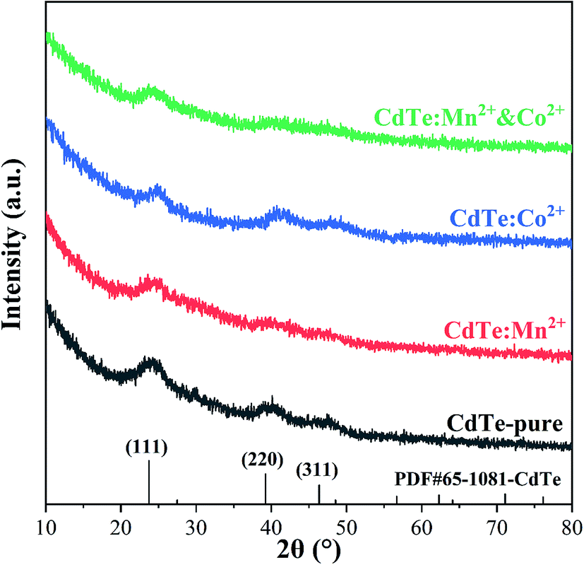 | ||
| Fig. 1 XRD patterns of pure CdTe QDs (CdTe-pure) and various doped QDs (CdTe:Mn2+, CdTe:Co2+ and CdTe:Mn2+&Co2+). | ||
Fig. 2 shows HRTEM images of pure CdTe QDs and various doped CdTe QDs (CdTe:Mn2+, CdTe:Co2+ and CdTe:Mn2+&Co2+). Crystalline with distinct lattice distances are observed for all samples, exhibits (111) and (220) planes of CdTe zinc blende, which is consistent with XRD pattern (see Fig. 1), indicating that all samples have high crystallinity, and doping does not change the structure of CdTe QDs. Insets of Fig. 2 are size distribution of QDs. The results show that CdTe-pure, CdTe:Mn2+, CdTe:Co2+ and CdTe:Mn2+&Co2+ QDs own diameters ranged from 3.4 nm to 3.7 nm, 3.8 nm to 4.2 nm, 3.6 nm to 3.8 nm, and 4.0 nm to 4.2 nm, respectively. Doping enlarges the size of CdTe QD. The QDs size increases in the order as: CdTe-pure, CdTe:Co2+, CdTe:Mn2+, CdTe:Mn2+&Co2+. In addition, sizes of the particles are all less than the Bohr exciton radius of CdTe (∼7 nm (ref. 34)).
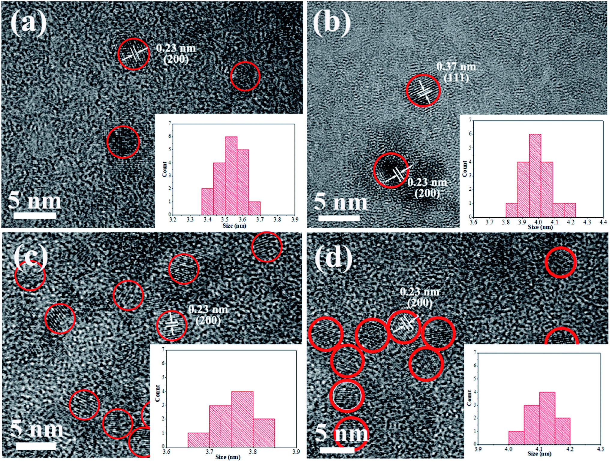 | ||
| Fig. 2 HRTEM images of pure CdTe QDs (a); the doped QDs prepared with Mn precursor (CdTe:Mn2+) (b); Co precursor (CdTe:Co2+) (c); and both Mn and Co precursor (CdTe:Mn2+&Co2+) (d). Insets: size distributions. | ||
Fig. 3 shows the typical XPS spectra of the undoped CdTe QDs (CdTe-pure) and the co-doped CdTe QDs (CdTe:Mn2+&Co2+). In Fig. 3a, the features at 404.9 and 411.6 eV for the undoped CdTe QDs are known to stem from Cd 3d5/2 and 3d3/2,14,16 respectively. The features at 571.9 and 582.4 eV of undoped CdTe QDs in Fig. 3b, corresponding to Te 3d5/2 and 3d3/2,14,16 respectively. Compared with undoped CdTe QDs, the binding energy of Cd and Te species in Fig. 3c and d for the co-doped QDs shifted to lower positions (Cd 3d shift form 404.9 and 411.6 eV to 404.1 and 410.9 eV, Te 3d shift form 571.9 and 582.4 eV to 571.4 eV and 581.7 eV). Fig. 3e and f are the high-resolution binding energy spectra for Mn and Co species, respectively. The peak of 652.2 eV, which can be attributed to Mn 2p, indicate the presence of Mn2+ species.29,35 The peaks observed at 795.1 eV and 782.3 eV can be assigned to Co 2p,36 and the satellite peaks (803.9 eV and 786.9 eV) also confirms the presence of Co2+ state. These results confirm the existence of Cd, Te, Mn and Co species in the co-doped QDs, and also indicate Mn2+ and Co2+ successfully doped in CdTe QDs. Moreover, based on ICP data, the actual cation ratio of Mn2+ and Cd2+ in the CdTe:Mn2+ is calculated to be 1.7 mol%, 98.3 mol%. The ratio of Co2+ and Cd2+ in the CdTe:Co2+ is calculated to be 2.2 mol%, 97.8 mol%, indicating that the actual doping concentration of Co2+ and Mn2+ is similar of a single doping. In co-doped QDs of CdTe:Mn2+&Co2+, the actual cation ratio of Mn2+, Co2+ and Cd2+ is calculated to be 3.0 mol%, 2.1 mol% and 94.9 mol%, respectively, also exhibiting that a similar doping concentration. The radii of Mn2+, Co2+, and Cd2+ ions are 0.67 nm, 0.745 nm, and 0.95 nm, respectively. A smaller radius gradient due to the presence of Co2+ as co-doping, which may causing Mn2+ is easier to dope into CdTe QDs.
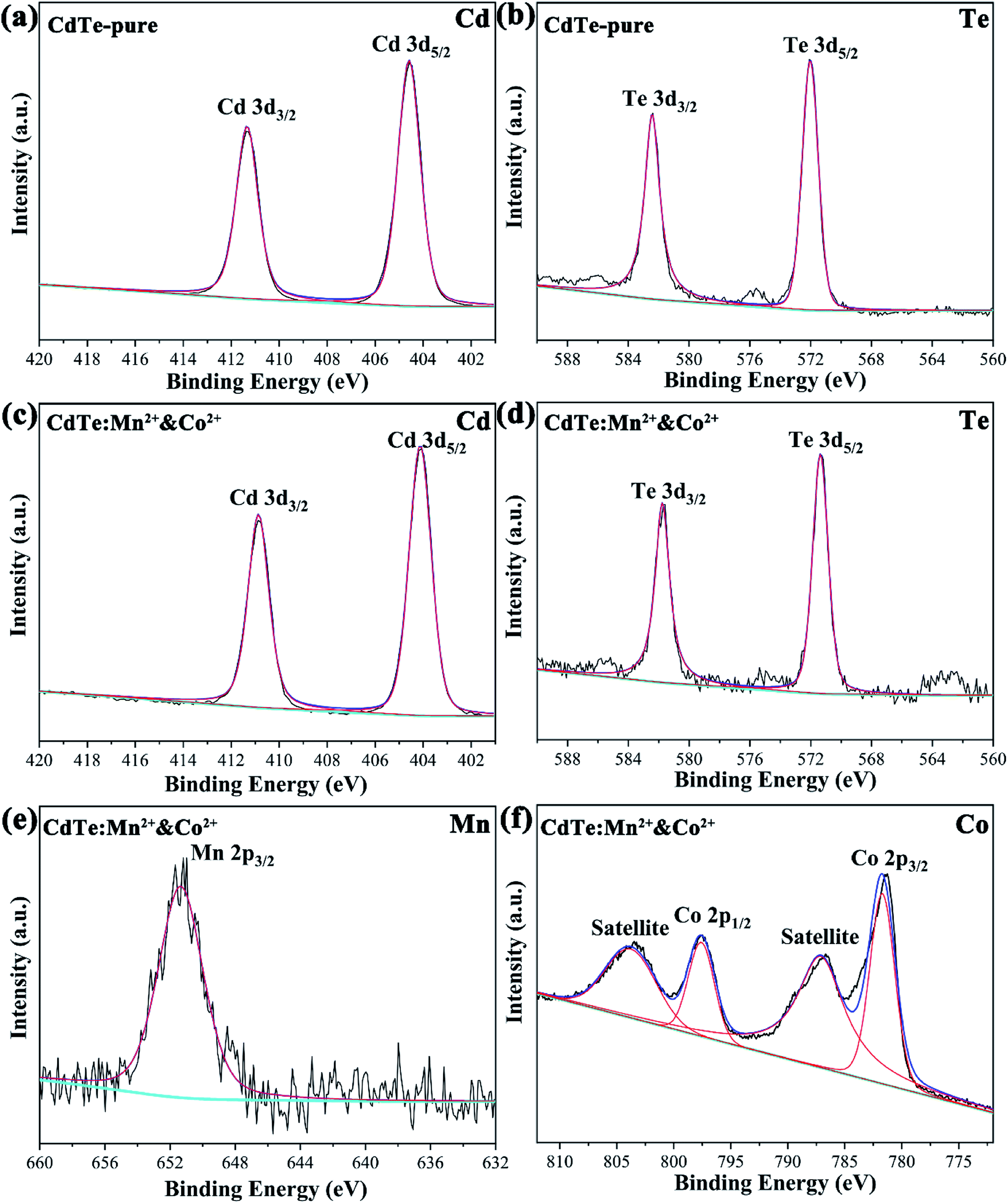 | ||
| Fig. 3 XPS spectra of the undoped CdTe QDs (CdTe-pure) (a and b) and the doped CdTe QDs (CdTe:Mn2+&Co2+) (c–f) binding energy spectra of Cd 3d (a and c), Te 3d (b and d), Mn 2p (e) and Co 2p (f). | ||
3.2. Optical properties of Mn2+ and Co2+ doped CdTe quantum dots
Fig. 4a shows optical absorption spectra of pure CdTe QDs and various doped CdTe QDs (CdTe:Mn2+, CdTe:Co2+ and CdTe:Mn2+&Co2+). Compared to the pure CdTe QDs, the optical absorption in the visible range of the doped samples increases and the absorption edge of all doped samples shift towards longer wavelength. In addition, the samples exhibit absorption peaks at 527 nm, 571 nm, 609 nm, and 609 nm of CdTe-pure, CdTe:Co2+, CdTe:Mn2+ and CdTe:Mn2+&Co2+, respectively. The red shift of optical absorption can be ascribed to the size evolution with doping. As described in Section 3.1, the QDs size increases in the order as: CdTe-pure, CdTe:Co2+, CdTe:Mn2+, CdTe:Mn2+&Co2+. Smaller size QD own larger bandgap because of quantum size effect. Therefore the optical absorption red shift in the order as: CdTe-pure, CdTe:Co2+, CdTe:Mn2+, CdTe:Mn2+&Co2+. Fig. 4b shows photoluminescence (PL) spectra of various CdTe QDs excited at 405 nm. The pure CdTe QDs shows a narrow emission peak centered at 568 nm. The full width at half maximum (FWHM) is about 45 nm, indicating a narrow size distribution. The emission peaks of all doped QDs shift towards higher wavelength compared to pure CdTe QDs. The samples of CdTe:Co2+, CdTe:Mn2+ and CdTe:Mn2+&Co2+ exhibit the PL peaks at 613 nm, 651 nm and 654 nm, respectively.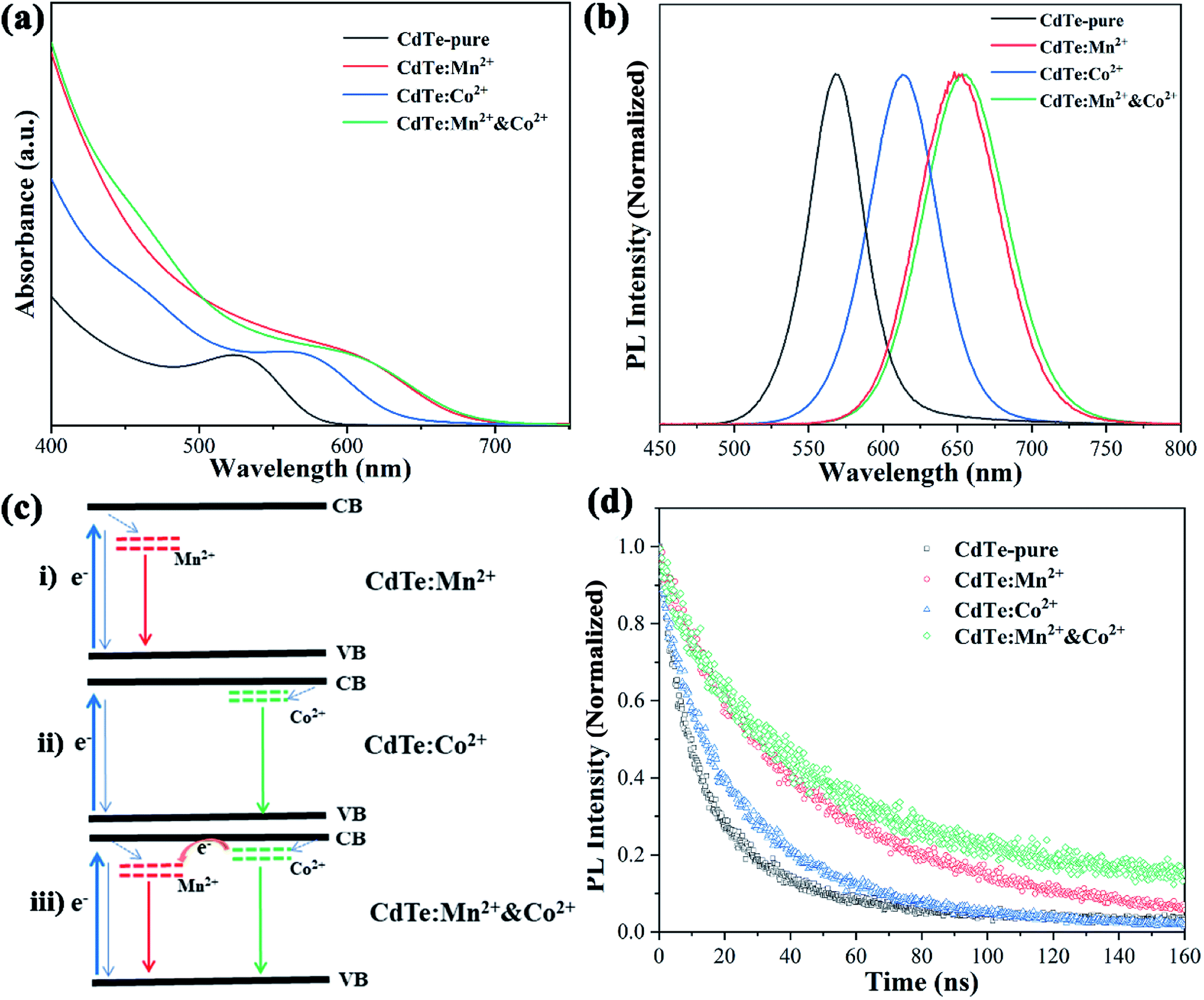 | ||
| Fig. 4 UV-vis absorption (a), photoluminescence (b) and photoluminescence decay spectra (d) of pure CdTe QDs and various doped QDs (CdTe:Mn2+, CdTe:Co2+ and CdTe:Mn2+&Co2+). Energy level diagram of the doped CdTe QDs (c). | ||
Following electron transfer process can be suggested for the emission origin. When light irradiates, electrons absorbs the energy of the photons, and excited from the valence band (VB) to the conduction band (CB) of CdTe. The excited electrons on the CB of CdTe will relax to the doping energy level, then recombine with holes, and emit fluorescence. PL spectra (Fig. 4b) shows that the emission wavelength becomes longer in the order of CdTe:Mn2+ > CdTe:Co2+ > CdTe-pure, indicating that the doping energy levels below the CB of CdTe, and the doping energy level of Mn2+ lower than that of Co2+. Accordingly, the energy level diagram of Mn2+ and Co2+ doped CdTe QDs is given in Fig. 4c. When Mn2+ and Co2+ co-doped, two doping levels are existing simultaneously as shown in Fig. 4c(iii).
The photoluminescence quantum yields (PLQY) of samples were calculated based on PL data and optical absorbance data by using the internal standard method and rhodamine B as a standard reference. The results showed that CdTe-pure, CdTe:Mn2+, CdTe:Co2+ and CdTe:Mn2+&Co2+ owned PLQYs of 20.3%, 34.1%, 14.7% and 32.2%, respectively. The doping energy levels in the band gap will increase the carrier concentration, resulting in increased PLQY. However, electrons and holes are more likely to recombine at the doping energy level of Co2+, resulting in a decrease in PLQY.
Fig. 4d shows PL decay spectra of pure CdTe QDs and various doped QDs (CdTe:Mn2+, CdTe:Co2+ and CdTe:Mn2+&Co2+). The recovery times of excited states for all samples are in the range of nanoseconds. For decay to the same PL intensity, the all doped samples need more time as shown in Table 1, indicating that the lifetime of excited electrons relaxed to the doping level is longer than that at the conduction band,24 resulting in the emission lifetimes of the doped QDs are much longer than that of pure CdTe QDs, the measured values were fitted to the eqn (1) and the average lifetimes were calculated using eqn (2):
 | (1) |
| τavg = (A1τ12 + A2τ22)/(A1τ1 + A2τ2) | (2) |
| Samples | A1 | τ1 (ns) | A2 | τ2 (ns) | τavg (ns) |
|---|---|---|---|---|---|
| CdTe-pure | 0.54 | 6.74 | 0.46 | 27.53 | 22.83 |
| CdTe:Mn2+ | 0.21 | 14.61 | 0.79 | 55.73 | 53.27 |
| CdTe:Co2+ | 0.64 | 14.52 | 0.36 | 50.34 | 38.10 |
| CdTe:Mn2+&Co2+ | 0.30 | 17.25 | 0.70 | 64.67 | 59.83 |
As shown in Fig. 4, Mn2+ doping significantly improves the optical performance of CdTe QDs than Co2+ doping. However, when Co2+ and Mn2+ co-doped, the Co2+-doping energy level is located between the conduction bands of CdTe and Mn2+-doping energy level, which is conducive to the transition of electrons. This is essential to enhance the performance of QDSCs.
3.3. Properties of Mn2+ and Co2+ doped CdTe quantum dot for sensitized solar cells
Fig. 5a shows JSC–VOC curves of QDSCs sensitized by the samples prepared with various precursors. The data such as photocurrent (Jsc), open circuit voltage (Voc), fill factor (FF) and efficiency (η) of corresponding cells are listed in Table 2, ten devices are tested, the statistical PCE present in Fig. S2,† the results show that the devices have good repeatability. Compared with sensitizer of CdTe-pure, the Jsc increases as doped Mn2+ (from 4.29 to 5.52, mA cm−2), due to doping Mn2+ can harvest more light range (see Fig. 4a) and the energy levels are matched electrons are more easily transferred from the Mn2+-doping energy level to the conduction band of TiO2. When CdTe QDs doped only Co2+, an increase of charge accumulation at the interface of QDs/TiO2 under illumination, therefore brings forward a greater upward shift of the TiO2 conduction band edge after sensitization and results in enhancement in photovoltage (from 384 to 550, mV) of the resultant cell devices.27,31 However, the Jsc decreases a lot (from 4.29 to 3.05, mA cm−2), the possible reason is that electrons and holes are easily recombined at the Co2+ doping level. For the sensitizer of CdTe:Mn2+&Co2+, both Voc (453 mV) and Jsc (10.74 mA cm−2) are remarkably greater than those of pure CdTe QDs (384 mV and 4.29 mA cm−2). As analyzed in Fig. 4c, the doping energy level formed by Mn2+ is lower than that by Co2+. Therefore, the schematic diagram of the energy diagram of CdTe:Mn2+&Co2+ is given as shown in Fig. 5b. As the sunlight irradiated, the electrons are excited to the conduction band of the CdTe QDs. The excited electrons transit to the Co2+-doping and to the Mn2+-doping energy levels, then finally injected into the conduction band of TiO2, making the electrons avoid recombination at Co2+-doping level and easier to transfer into TiO2, resulting in the Jsc increase significantly. Meanwhile, doping Co2+ will still induce an increase of charge accumulation at the interface of QDs/TiO2 under illumination and therefore brings forward upward shift of the TiO2 conduction band edge after sensitization and results in enhancement in Voc of the cell devices. Accordingly, Co2+ and Mn2+ co-doping can enhance the PCE of QDSCs. The efficiency is enhanced from 0.87% to 2.26%, which is more than 159% enhancement using a single doping procedure.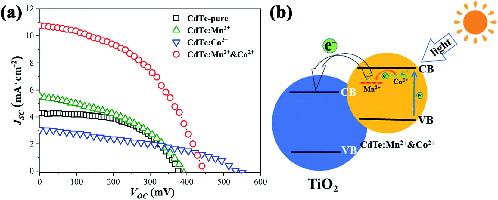 | ||
| Fig. 5 (a) JSC–VOC curves for solar cells sensitized of CdTe-pure, CdTe:Mn2+, CdTe:Co2+ and CdTe:Mn2+&Co2+; (b) schematic representation of the energy diagram of CdTe:Mn2+&Co2+. | ||
| Sensitizer | τ (ns) | Voc (mV) | Jsc (mA) | FF | η (%) |
|---|---|---|---|---|---|
| CdTe-pure | 22.83 | 384.00 | 4.29 | 0.53 | 0.87 |
| CdTe:Mn2+ | 53.27 | 392.00 | 5.52 | 0.42 | 0.91 |
| CdTe:Co2+ | 38.10 | 550.00 | 3.05 | 0.37 | 0.62 |
| CdTe:Mn2+&Co2+ | 59.83 | 453.00 | 10.74 | 0.46 | 2.26 |
Doped QDs with various transition metals have a general beneficial effect on the performance of QDSCs. Recombination of electrons and holes is limited with doping of Mn2+ as the d–d transition is orbit ally forbidden,35 Co2+ doping make electrons transit to the conduction band of TiO2 easier, and also increases the Voc, which is benefit to the enhancement of the performance of QDSCs. In addition, red shifts in optical absorption of the sample induce an enhancement in optical absorption of AM 1.5G. Therefore, combine Mn2+ and Co2+ complement each other is a better way for the design of higher efficiency QDSCs.
4. Conclusions
Mn2+-, Co2+-doped CdTe QDs and Mn2+&Co2+ co-doped CdTe QDs with narrow size distribution were successfully synthesized via aqueous phase method with MPA. All of the samples possess zinc blende crystal structure. Doping Mn2+ and Co2+ is more conducive to improving optical properties compared with pure CdTe QDs due to the new doping energy levels. Combine Mn2+ and Co2+ complement each other, broader light harvesting range of the doped CdTe QDs has been observed. The retarded charge recombination have been confirmed by PL decay characterizations. As observed by PL decay measurements, doping with both Mn2+ and Co2+ result in a significant increase in the emission lifetime and high PLQY. In addition, QDSCs sensitized by the Mn2+&Co2+ co-doped QDs possesses much higher efficiency than that of sensitized by the pure CdTe QDs.Conflicts of interest
The authors declare no conflicts of interest in relation to this paper.Acknowledgements
This research is supported by the Natural Science Foundation of Zhejiang Province of China (Grant No. LY18E020002).References
- Y. F. Xu, W. Q. Wu, H. S. Rao, H. Y. Chen, D. B. Kuang and C. Y. Su, Nano Energy, 2015, 11, 621–630 CrossRef CAS
.
- S. Jiao, J. Du, Z. L. Du, D. H. Long, W. Y. Jiang, Z. X. Pan, Y. Li and X. H. Zhong, J. Phys. Chem. Lett., 2017, 8, 559–564 CrossRef CAS
- J. M. Luther, M. C. Beard, Q. Song, M. Law, R. J. Ellingson and A. J. Nozik, Nano Lett., 2007, 7, 1779–1784 CrossRef CAS
- K. Zhao, Z. X. Pan, I. Mora-Sero, E. Canovas, H. Wang, Y. Song, X. Q. Gong, J. Wang, M. Bonn, J. Bisquert and X. H. Zhong, J. Am. Chem. Soc., 2015, 137, 5602–5609 CrossRef CAS
- S. Kundu and A. Patra, Chem. Rev., 2017, 117, 712–757 CrossRef CAS
- P. V. Kamat, J. Phys. Chem. Lett., 2013, 4, 908–918 CrossRef CAS
- K. Zhao, Z. X. Pan and X. H. Zhong, J. Phys. Chem. Lett., 2016, 7, 406–417 CrossRef CAS
- R. D. Schaller, M. Sykora, J. M. Pietryga and V. I. Klimov, Nano Lett., 2006, 6, 424–429 CrossRef CAS
- J. Du, Z. L. Du, J. S. Hu, Z. X. Pan, Q. Shen, J. K. Sung, D. H. Long, H. Dong, L. T. Sun, X. H. Zhong and L. J. Wan, J. Am. Chem. Soc., 2016, 138, 4201–4209 CrossRef CAS
- N. H. Song, H. M. Zhu, S. Y. Jin and T. Q. Lian, ACS Nano, 2011, 5, 8750–8759 CrossRef CAS
- Z. W. Ren, Z. Q. Wang, R. Wang, Z. X. Pan, X. Q. Gong and X. H. Zhong, Chem. Mater., 2016, 28, 2323–2330 CrossRef CAS
- Z. L. Du, Z. X. Pan, F. Fabregat-Santiago, K. Zhao, D. H. Long, H. Zhang, Y. X. Zhao, X. H. Zhao, J. S. Yu and J. Bisquert, J. Phys. Chem. Lett., 2016, 7, 3103–3111 CrossRef CAS
- Z. X. Pan, L. Yue, H. S. Rao, J. Zhang, X. H. Zhong, Z. L. Zhu and A. K. Y. Jen, Adv. Mater., 2019, 31, 1903696 CrossRef CAS
- S. J. Ding, S. Liang, F. Nan, X. L. Liu, J. H. Wang, L. Zhou, X. F. Yu, Z. H. Hao and Q. Q. Wang, Nanoscale, 2015, 7, 1970–1976 RSC
- L. H. Jing, S. V. Kershaw, Y. L. Li, X. Huang, Y. Y. Li, A. L. Rogach and M. Y. Gao, Chem. Rev., 2016, 116, 10623–10730 CrossRef CAS
- A. Ayyaswamy, S. Ganapathy, A. Alsalme, A. Alghamdi and J. Ramasamy, Superlattice. Microst., 2015, 88, 634–644 CrossRef CAS
- J. W. Yang and X. H. Zhong, J. Mater. Chem. A, 2016, 4, 16553–16561 RSC
- S. J. Zhou and L. W. Yin, J. Alloy. Compd., 2017, 691, 1040–1048 CrossRef CAS
- V. A. Vlaskin, N. Janssen, J. van Rijssel, R. Beaulac and D. R. Gamelin, Nano Lett., 2010, 10, 3670–3674 CrossRef CAS
- N. Pradhan and D. D. Sarma, J. Phys. Chem. Lett., 2011, 2, 2818–2826 CrossRef CAS
- W. Zheng, P. Huang, D. T. Tu, E. Ma, H. M. Zhu and X. Y. Chen, Chem. Soc. Rev., 2015, 44, 1379–1415 RSC
- M. J. Yuan, O. Voznyy, D. Zhitomirsky, P. Kanjanaboos and E. H. Sargent, Adv. Mater., 2015, 27, 917–921 CrossRef CAS
- N. S. Karan, D. D. Sarma, . R. M. Kadam and N. Pradhan, J. Phys. Chem. Lett., 2010, 1, 2863–2866 CrossRef CAS
- S. K. Panda, S. G. Hickey, H. V. Demir and A. Eychmuller, Angew. Chem. Int. Ed., 2011, 50, 4432–4436 CrossRef CAS
- H. Y. Chen, S. Maiti and D. H. Son, ACS Nano, 2012, 6, 583–591 CrossRef CAS
- B. B. Srivastava, S. Jana, N. S. Karan, S. Paria, N. R. Jana, D. D. Sarma and N. Pradhan, J. Phys. Chem. Lett., 2010, 1, 1454–1458 CrossRef CAS
- P. K. Santra and P. V. Kamat, J. Am. Chem. Soc., 2012, 134, 2508–2511 CrossRef CAS
- D. H. Phuc and H. Tung, Int. J. Photoenergy, 2019 DOI:10.1155/2019/9812719
- J. J. Tian, L. L. Lv, C. B. Fei, Y. J. Wang, X. G. Liu and G. Z. Cao, J. Mater. Chem. A, 2014, 2, 19653–19659 RSC
- N. Firoozi, H. Dehghani and M. Afrooz, J. Power Sources, 2015, 278, 98–103 CrossRef CAS
- T. R. Tatarchuk, N. D. Paliychuk, M. Bououdina, B. Al-Najar, M. Pacia, W. Macyk and A. Shyichuk, J. Alloy. Compd., 2018, 731, 1256–1266 CrossRef CAS
- S. Ebrahim, W. Ramadan and M. Ali, J. Mater. Sci. Mater. Electron., 2016, 27, 3826–3833 CrossRef CAS
- P. Piotrowski and W. Pacuski, J. Lumin., 2020, 221, 117047 CrossRef CAS
- R. Ulbricht, J. J. H. Pijpers, E. Groeneveld, R. Koole, C. M. Donega, D. Vanmaekelbergh, C. Delerue, G. Allan and M. Bonn, Nano Lett., 2012, 12, 4937–4942 CrossRef CAS
- J. Wang, Y. Li, Q. Shen, T. Izuishi, Z. X. Pan, K. Zhao and X. H. Zhong, J. Mater. Chem. A, 2015, 4, 877–886 RSC
- G. H. Ren, Z. W. Li, W. Wu, S. Han, C. Y. Liu, Z. Q. Li, M. N. Dong and W. B. Guo, Appl. Surf. Sci., 2020, 507, 145081 CrossRef CAS
Footnote |
| † Electronic supplementary information (ESI) available. See DOI: 10.1039/d0ra06381a |
| This journal is © The Royal Society of Chemistry 2020 |