DOI:
10.1039/D0RA05433J
(Paper)
RSC Adv., 2020,
10, 35619-35635
The effect of lithium on structural and luminescence performance of tunable light-emitting nanophosphors for white LEDs
Received
21st June 2020
, Accepted 17th September 2020
First published on 28th September 2020
Abstract
Li+ incorporated tunable Y2O3:Eu3+ red-emitting nanophosphors were synthesized using a wet chemical method. The effect of Li+ on structural and luminescence properties of the nanophosphors were studied in detail. The structural results exhibited that nanophosphors have a body-centered cubic (I) phase with point group symmetry m![[3 with combining macron]](https://www.rsc.org/images/entities/char_0033_0304.gif) . No additional impurity peaks were observed within the range of the XRD pattern due to the Li+ ion. FTIR spectra reveal the formation of the pure and crystalline structure of the nanophosphors. TEM results show the prepared nanophosphors were highly crystalline and polycrystalline in nature. PL studies show the highly enhanced emission band due to the flux effect, greatly improved crystallinity caused by the Li+ ion, and the different excitation wavelengths. The most intense luminescence band was observed at 612 nm for red emission ascribed to the 5D0 → 7F2 transition of Eu3+ ion upon 254, 393, and 465 nm excitations in the C3i and C2 symmetry site of Y2O3 respectively. The highly enhanced emission band was observed under excitation at 254 nm and is 6.9 and 3.67 times higher than the emission band excited at 393 and 466 nm, respectively. The average lifetime also varies with different concentrations of Li+ ions. The chromaticity color coordinates, CCT values, were tuned in the red region of the color space. Hence, the results indicate that the prepared nanophosphor can be used as a red component to construct the white light for light-emitting diode applications.
. No additional impurity peaks were observed within the range of the XRD pattern due to the Li+ ion. FTIR spectra reveal the formation of the pure and crystalline structure of the nanophosphors. TEM results show the prepared nanophosphors were highly crystalline and polycrystalline in nature. PL studies show the highly enhanced emission band due to the flux effect, greatly improved crystallinity caused by the Li+ ion, and the different excitation wavelengths. The most intense luminescence band was observed at 612 nm for red emission ascribed to the 5D0 → 7F2 transition of Eu3+ ion upon 254, 393, and 465 nm excitations in the C3i and C2 symmetry site of Y2O3 respectively. The highly enhanced emission band was observed under excitation at 254 nm and is 6.9 and 3.67 times higher than the emission band excited at 393 and 466 nm, respectively. The average lifetime also varies with different concentrations of Li+ ions. The chromaticity color coordinates, CCT values, were tuned in the red region of the color space. Hence, the results indicate that the prepared nanophosphor can be used as a red component to construct the white light for light-emitting diode applications.
1. Introduction
Over the last several decades, rare earth (RE) doped luminescence materials have attracted broad research interest, because of their potential application in various fields. Eu3+ activated Y2O3 materials have been widely used as a red-emitting nanophosphor in the white-light-emitting diodes, plasma display panels (PDPs), field emission displays (FEDs), and cathode ray tube (CRTs).1–3 They have high luminous efficiency, excellent luminescence properties, high quantum efficiency, color purity, high brightness, and good atmospheric stability.4 This nanophosphor based LED can be used to replace incandescent and fluorescent lamps due to their longer lifetime, lower energy consumption and eco-friendly behavior. They don't use toxic elements such as mercury as an excitation light source. The Eu3+ ion can reveal both the divalent and trivalent valence state among the various RE elements. Therefore, Eu3+ doped phosphors are used to produce blue, green, and red luminescence efficiently based on various host materials.5 The Eu3+ ion exhibits a prominent red emission band due to the 5D0 → 7F2 transition at about 612 nm and is used as a red component for white LED fabrication.6 Because of the special character, Eu3+ ion has been widely used as an activator in different nanophosphors.
It is well known that Li+ ion as a codopant is widely used to improve luminescence efficiency and enhanced the emission band intensity. The important role of the Li+ ion is to serve as flux materials, resulting in the higher crystallinity and growth of the crystallite size.7,8 Wang et al. reported that photoluminescence intensity of Y2O3:Eu3+ thin-films phosphors were greatly improved by the addition of Li+ ion.9 The phosphor emission band intensity was enhanced by around 3.5 times with Li+ ions. The reason for highly enhancement photoluminescence intensity was improved crystallinity, increase optical volume, and changes the concentration of oxygen vacancies caused by the flux effect of Li+ ion. Li Yongquiang et al. found that the enhancement of photoluminescence intensity of Y2O3:5% Eu3+, x% Li+ phosphor thin film, from 0–15% with increasing Li+ doping concentration and then declines with Li+ doping further due to the creation of oxygen vacancies in the phosphors.10 Very recently, Ashim et al. developed the Froster resonance energy transfer (FRET) based on rare earth material free white light-emitting colloidal luminescent due (LD) namely DCM@N-GQDs0.7 with an energy efficiency ∼30%. The F-LED exhibits an emission overlapping (56%) with the solar spectrum (AM 1.5) in the visible region which is two times higher than the commercial LED. They also tuned the PL emission in the blue and red regions by changing the D-A ratio.11 Quan et al. has fabricated a white light-emitting diode by mixing S, N-codoped oil-soluble carbon dots with epoxy and drop-casting the mixture on the gallium nitride (GaN) surface-based blue chips. This shows the excellent color property to fabricate WLED. The CCT, CIE and CRI values were found to be 5389 K, (0.33, 0.30) and 88.38, respectively.12 The quantum yield optimized of white-emitting CdSe QDs up to 22% by controlling the synthesis parameters of reaction time and temperature. Where the broad emission band was observed in the visible region and the color rendering index, luminous efficiency showed up to 89 and 11.7 lm W−1, respectively.13
In this work, we have analyzed the enhancement of emission intensity for Y2O3:4 at% Eu3+ nanophosphors, prepared by a wet chemical method with xLi+ (x = 0.5, 1, 3, 5, 7, 9 at%) co-doping from a new angle. This is well known that the variation of luminescence intensity depends on the doping concentration. With the increase of the doping concentration, the luminescent intensity enhances at first then drops down quickly. This is due to the concentration quenching effect, and the inflection point is known as the concentration quenching threshold. The concentration quenching phenomenon results from the energy transfer within neighboring ions. Here we have only investigated the effect of the codoped Li+ ion for the structural study and compare the enhances the luminescent intensity of Y2O3:Eu3+ nanophosphor under various excitation wavelengths. In the case of our study, PL emission intensity greatly increased from 0.5 to 7 at% codoping of Li+ concentration after that it decreased. Thus the 7 at% codoping concentration possessed the strongest luminescence emission intensity as a concentration quenching threshold. The structural study shows that no additional impurity peaks were exhibited within the whole range of the XRD pattern due to the Li+ codopant. Besides, the effect of Li+ on the crystal structure, internal morphology, and colorimetric performance are studied in detail.
2. Experimental section
2.1. Materials and methods
A series of xLi+ (x = 0.5, 1, 3, 5, 7, 9 at%) co-activated Y2O3:4 at% Eu3+ nanophosphors were prepared by wet chemical methods.14 For the preparation of the nanophosphor, yttrium(III) acetate hydrate (CH3·CO2)3Y·xH2O (Alfa Aesar 99.99%), europium(III) oxide (Eu2O3) (Sigma Aldrich 99.99%), and lithium acetate (C2H3LiO2) (Sigma-Aldrich, 99.95%, purity) were used as starting materials. Initially, 0.5 g yttrium(III) acetate hydrate (CH3·CO2)3Y·xH2O (Alfa Aesar 99.99%) and the calculated amount of (4 at%) Eu2O3 (Sigma Aldrich 99.99%) was mixed with 10 ml of dilute hydrochloric acid. The mixtures were stirred vigorously to get a clear solution. The solution was evaporated many times in double distilled water to remove excess acids from the solution. The solution was poured into a 250 ml round bottom flask having a condenser. Polyethylene glycol of 25 ml was added and warms the solution until it got clear. Then, 1 M strength sodium hydroxide (AR) was added into the observed clear solution and heated continuously the mixture up to 140 °C. The solution was observed as foggy white precipitate and continued the reaction for three hours. To remove the additional ligands, the forming white precipitate was washed several times using double distilled water and methanol under the centrifugation process. Finally, the residue was collected and considered as Y2O3:4 at% Eu3+ nanoparticles. To incorporate xLi+ ions in Y2O3:4 at% Eu3+, lithium acetate (C2H3LiO2) (Sigma-Aldrich, 99.95%, purity) was initially dissolved in double distilled water to get Li+ ions and is simply added into the mixture of Y3+ and Eu3+ and follows the same procedure were followed as to prepare Y2O3:4 at% Eu3+ nanoparticles. The prepared sample was annealed at 900 °C for 3 h. These synthesized nanomaterials were kept continuously in the furnace for cool down to room temperature and ground for further characterization to observe the structural and luminescence properties.
2.2. Materials characterization
X-ray diffraction (XRD) data were obtained by Explorer, GNR Instrument and Analysis, Italy using Cu Kα radiation source and a monochromatic wavelength (λ = 1.5406 Å) operating at 40 kV tube voltage and 35 mA tube current with 2θ angle ranging from 10 to 80°. The Rietveld refinement,15 quantitative structural analysis was conducted using FullProf Suite,16 software package. The crystal structure and the profile matching parameters data of cubic Y2O3 were taken from Crystallographic Open Database (COD). The internal morphology and particle size micrographs were taken by a high-resolution transmission electron microscopy (HRTEM) which was performed with (JEOL, JEM-2100) electron microscope with a tungsten filament gun operating at an accelerating voltage 200 kV. The samples for TEM were prepared by drying a drop of methanol ultrasonically dispersion of 5 mg sample for 1 h on a carbon-coated Cu-grid. The selected area electron diffraction (SAED) patterns were also obtained. The Fourier transform infrared (FTIR) spectra of the nanophosphor were monitored within the mid-IR region using KBr pellet techniques by Bruker (Model: Alpha) spectrometer. All photoluminescence (PL) measurements were observed on a Hitachi F-7000 Fluorescence Spectrophotometer at room temperature with slit width kept open for 3 nm, having a 150 W Xe arc lamp as an excitation light source. The Commission Internationale de l'Éclairage (CIE) 1931 color calculator was used to evaluating the chromaticity color coordinates (x, y) from the PL emission spectra.
3. Results and discussion
3.1. Structural characterization
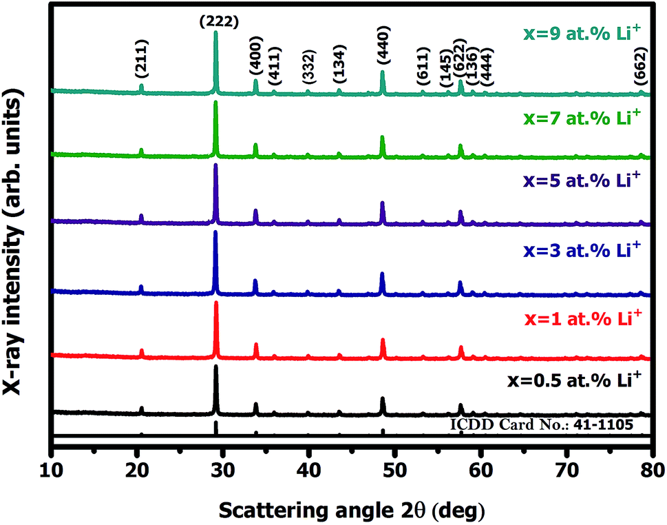
3.1.1. Qualitative X-ray diffraction analysis. Fig. 1 represents the X-ray diffraction (XRD) patterns of Y2O3:4 at% Eu3+, xLi+ (x = 0.5, 1, 3, 5, 7, 9 at%) nanophosphors. All the diffraction peaks are in good agreement with the standard International Centre for Diffraction Data (ICDD) Card No. 41-1105 corresponding to the cubic structure of Y2O3 with Ia (Number 206, Z = 16) space group. No additional peaks of other phases were observed in the XRD diffraction pattern. It indicates Li+ ion was incorporated into the host lattice, there is no effect observed on the XRD pattern. The average crystallite size (D) of the prepared sample was estimated from the prominent diffraction peak of (222) plane using Debye–Scherrer equation:17| |
 | (1) |
where k = 0.9 is the dimensionless shape factor (Scherrer constant), λ = 1.5405 Å is the wavelength of X-ray radiation used, β is the Full width at half maximum (FWHM) in radians, θ is the Bragg angle in degrees of diffraction peaks. Based on this relation, the calculated average crystallite sizes of Y2O3:4 at% Eu3+, xLi+ (x = 0.5, 1, 3, 5, 7, 9 at%) nanophosphors were obtained within nanoscale range from 50 to 55 nm. Further, the effective lattice strain (ε) associated with nanophosphors were calculated by Williamson–Hall (W–H) plots using the relation:18| |
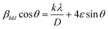 | (2) |
where βhkl represents full width at half maximum (FWHM) in radians and D represents the effective crystallite size present in the sample. The effective lattice strain values were obtained from the slope of the linear fit by plotting 4![[thin space (1/6-em)]](https://www.rsc.org/images/entities/char_2009.gif) sinθ along the x-axis versus βhklcosθ along the y-axis. Fig. 2(a) the Williamson–Hall plots of Y2O3:4 at% Eu3+, xLi+ (x = 3 at%) nanophosphors, where five major peaks with miller indices (211), (222), (400), (440) and (622) were used. It is observed that the lattice strain increases with increasing Li+ concentration. The lower value of lattice strain (ε) indicates a lower level of lattice imperfection present in the crystal.19 The diffraction peaks were also observed slightly shifts towards the lower angle (2θ) side which indicates the variations in the lattice parameters can occur of the nanophosphors. This variation of lattice parameters (a) is calculated using the formula as follows:20
sinθ along the x-axis versus βhklcosθ along the y-axis. Fig. 2(a) the Williamson–Hall plots of Y2O3:4 at% Eu3+, xLi+ (x = 3 at%) nanophosphors, where five major peaks with miller indices (211), (222), (400), (440) and (622) were used. It is observed that the lattice strain increases with increasing Li+ concentration. The lower value of lattice strain (ε) indicates a lower level of lattice imperfection present in the crystal.19 The diffraction peaks were also observed slightly shifts towards the lower angle (2θ) side which indicates the variations in the lattice parameters can occur of the nanophosphors. This variation of lattice parameters (a) is calculated using the formula as follows:20| |
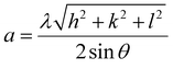 | (3) |
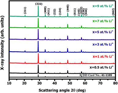 |
| | Fig. 1 X-ray diffraction (XRD) pattern of Y2O3:4 at% Eu3+, xLi+ (x = 0.5, 1, 3, 5, 7, 9 at%) nanophosphors. | |
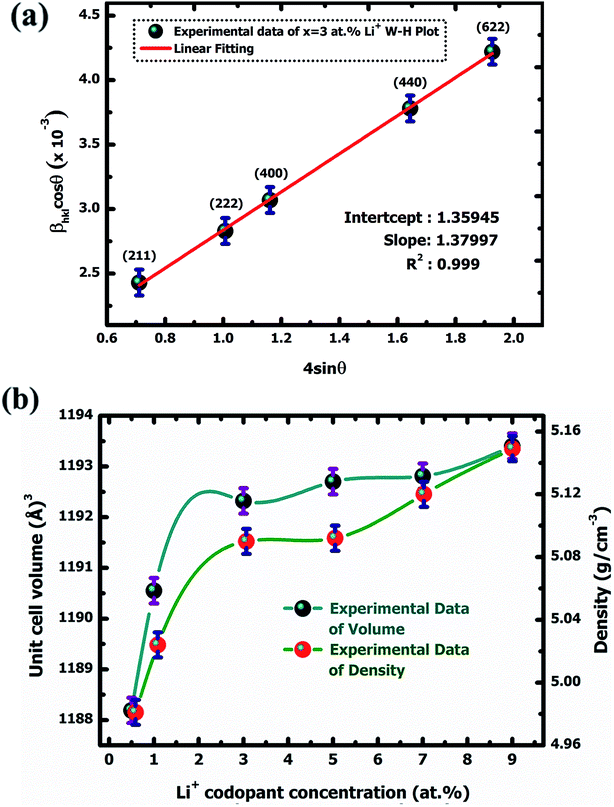 |
| | Fig. 2 W–H plot of Y2O3:4 at% Eu3+, xLi+ (a) x = 3 at% nanophosphor (b) variation of unit cell volume and density with Li+ codoping concentration. | |
The calculated lattice parameters were found to increase with increasing doping Eu3+ and codoping Li+ concentration. This is understandable that the ionic radius of Eu3+ (1.06 Å) has larger than those of Y3+ (1.01 Å) and Li+ (0.9 Å). The orderly increases lattice parameter indicates that the ions were occupied in the Y3+ site in the lattice. The unit cell volume also increased with increasing co-doping Li+ concentration due to the lattice expansion in the crystal. All the qualitative structural parameters of the prepared samples are listed in Table 1.
Table 1 Structural parameters of Y2O3:4 at% Eu3+, xLi+ (x = 0.5, 1, 3, 5, 7, 9 at%) nanophosphors
| Nanophosphor |
Li+ concentration (at%) |
2θ (°) |
Miller indices hkl |
Lattice constants a (Å) |
Crystallite size (nm) |
Lattice strain ε (× 10−3) (W–H) |
Volume of unit cell a3 (Å) |
| Calculated |
Observed |
Calculated |
Observed |
Debye–Scherrer |
| Y2O3:4 at% Eu3+, x Li+ |
x = 0.5 |
29.21 |
(2 2 2) |
(2 2 2) |
10.604 |
10.582 |
50.08 |
1.177 |
1184.95 |
| x = 1 |
29.18 |
(2 2 2) |
(2 2 2) |
10.604 |
10.593 |
51.02 |
1.214 |
1188.65 |
| x = 3 |
29.16 |
(2 2 2) |
(2 2 2) |
10.604 |
10.600 |
52.85 |
1.379 |
1191.01 |
| x = 5 |
29.15 |
(2 2 2) |
(2 2 2) |
10.604 |
10.603 |
53.95 |
1.442 |
1192.02 |
| x = 7 |
29.14 |
(2 2 2) |
(2 2 2) |
10.604 |
10.607 |
54.97 |
1.478 |
1193.37 |
| x = 9 |
29.13 |
(2 2 2) |
(2 2 2) |
10.604 |
10.610 |
55.26 |
1.495 |
1194.38 |
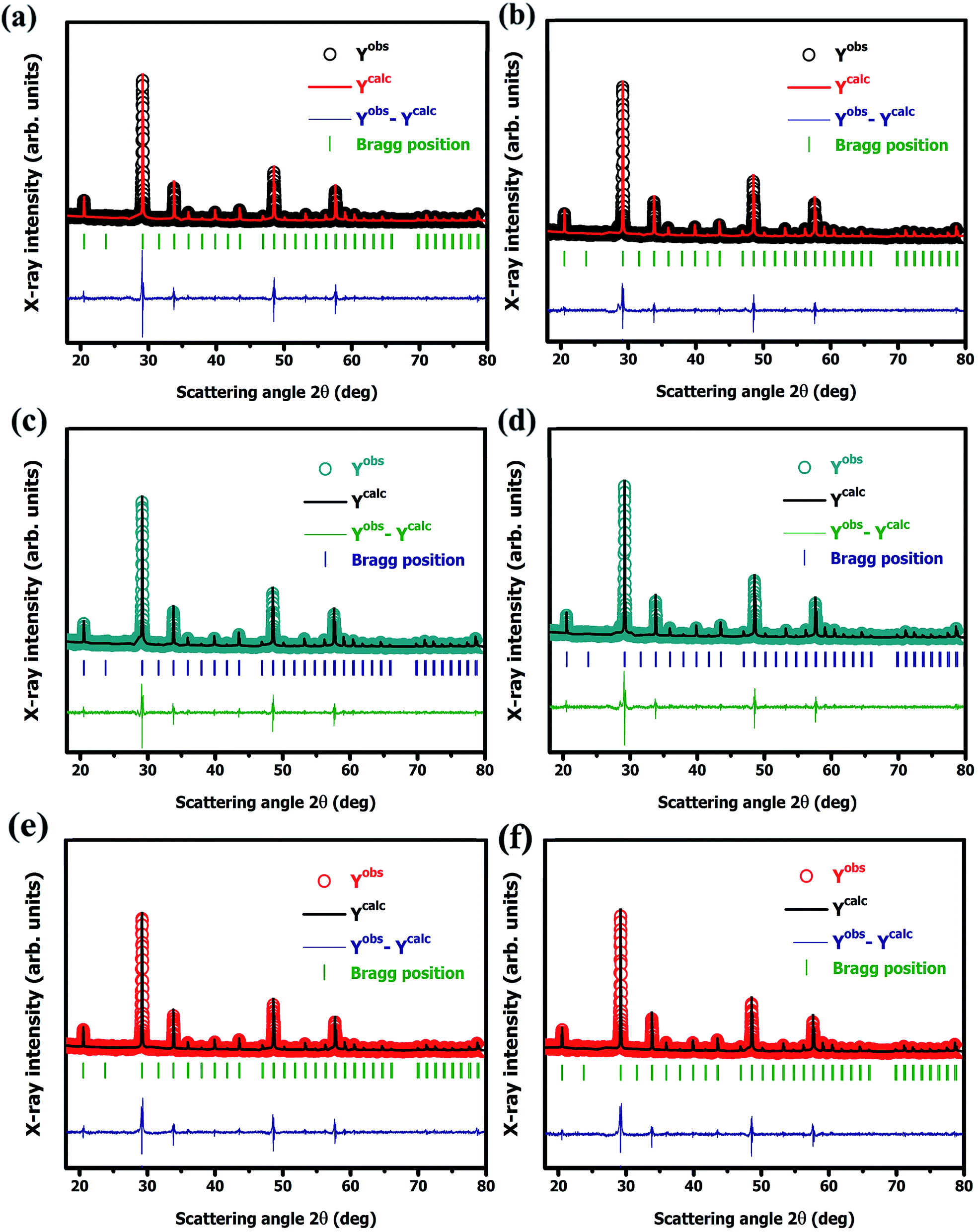
3.1.2. Quantitative X-ray diffraction (XRD) analysis. Quantitative X-ray diffraction (XRD) analysis of Y2O3:4 at% Eu3+, xLi+ (x = 0.5, 1, 3, 5, 7, 9 at%) nanophosphors was performed by the Rietveld refinement method.21 All the structural parameters were evaluated through the FullProf Suite crystallographic program using powder XRD data. The obtained structural refined parameters are summarized in Table 2. The Pseudo-Voigt function i.e., the summation of a Gaussian and Lorentzian function was utilized to fit various parameters to the data point. The patterns were typically fitted with parameters such as backgrounds, cell parameters; scale factor, zero shiftings, shape and width of the peaks, atomic coordinates, isothermal temperature factors, and asymmetric factors. The refinement result exhibited that nanophosphors have a body-centered cubic (I) phase with point group symmetry m. The fitting parameters Rwp, Rex, GoF, Rp, RBragg, RF, and χ2 were also shown a good agreement with the observed and calculated XRD patterns. The observed, calculated, and difference between observed and calculated XRD patterns for nanophosphors are shown in Fig. 3(a), (b), (c), (d), (e), and (f), respectively. The quality of refinement data was examined by the lower values of the goodness of fit (GoF) which is obtained by the ratio of expected and weighted profile of R factors i.e., GoF = Rwp/Rexp. For the best refinement, GoF must approach less than two. In this case, GoF values were found to be 1.21, 1.01, 1.00, 1.20, 1.07, and 1.09 respectively which confirmed our fitting is best. By observing unit cell volume and density it shows increases continuously with increasing co-dopant Li+ concentration which is due to the substitution of Li+ to the host Y2O3 in increasing order from (0.5–9 at%). Fig. 2(b) shows the variation of unit cell volume and density with increasing Li+ codoping concentration.
Table 2 Reitveld refinement parameters of Y2O3:4 at% Eu3+, xLi+ (x = 0.5, 1, 3, 5, 7, 9 at%) nanophosphors
| Nanophosphor |
Li+-concentration (at%) |
Rietveld refinement parameters |
| Rwp |
Rexp |
GoF |
Rp |
RBragg |
RF |
χ2 |
Cell volume a3 (Å) |
Density g cm−3 |
| Y2O3:4 at% Eu3+, x Li+ |
x = 0.5 |
23.8 |
19.64 |
1.21 |
36.8 |
6.45 |
6.07 |
1.47 |
1188.19 |
5.149 |
| x = 1 |
24.4 |
23.05 |
1.05 |
44.0 |
4.57 |
4.27 |
1.12 |
1190.55 |
5.120 |
| x = 3 |
22.3 |
22.26 |
1.00 |
41.5 |
2.84 |
3.29 |
1.00 |
1192.32 |
5.092 |
| x = 5 |
22.3 |
18.55 |
1.20 |
37.9 |
8.59 |
6.69 |
1.53 |
1192.70 |
5.090 |
| x = 7 |
23.0 |
21.43 |
1.07 |
41.0 |
4.46 |
4.26 |
1.15 |
1192.81 |
5.024 |
| x = 9 |
21.8 |
19.95 |
1.09 |
33.9 |
4.93 |
4.09 |
1.20 |
1193.04 |
4.978 |
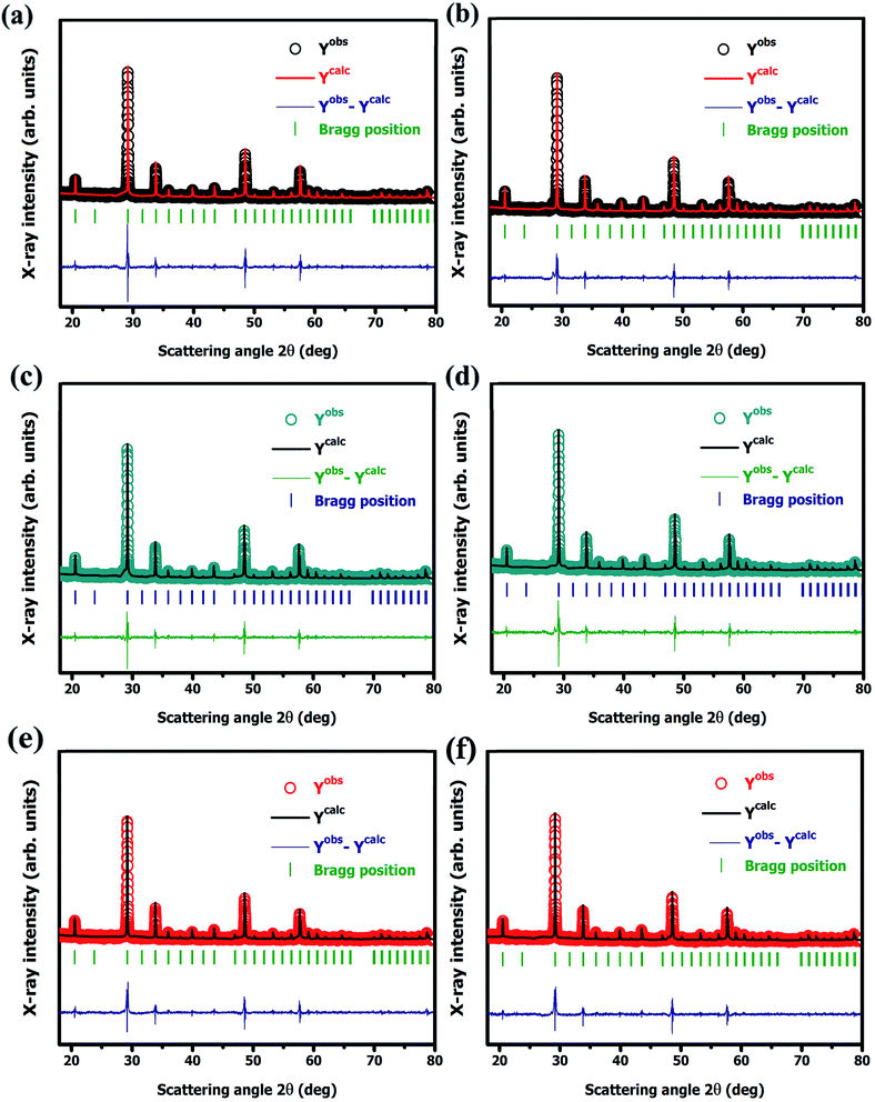 |
| | Fig. 3 Rietveld refined XRD pattern of Y2O3:4 at% Eu3+, xLi+ nanophosphors (a) x = 0.5 at%, (b) x = 1 at% (c) x = 3 at%, (d) x = 5 at%, (e) x = 7 at%, and (f) x = 9 at%, respectively. | |
All the crystal structures were modeled through a three-dimensional visualization program called Visualization for Electronic and Structural Analysis (VESTA) using Y2O3:4 at% Eu3+, xLi+ (x = 7 at%) nanophosphors refinement data.22 The refined parameters such as occupancy, atomic coordinates, phase, space group, and lattice parameters were used to model these structures. Fig. 4(a) illustrates the crystal structure of cubic yttrium(III) oxide (Y2O3). It contains 32 cations which are the summation of two partially distributed cation Y3+(1) located at 24d site (Wyckoff position) with C2 (noncentrosymmetric) symmetry and Y3+(2) located at 8b (Wyckoff position) site with C3i(S6) (centrosymmetric) inversion symmetry of the crystallographic lattice. Oxygen ions were occupied at the 48e site (Wyckoff position) of the Y2O3 host lattice. In the Y2O3 crystal structure, both the cations Y3+(C2) and Y3+(C3i) have made six-fold octahedral coordination with oxygen thus forming the [YO6] octahedron structure having 8 faces, 12 edges and 6 vertices are shown in Fig. 4(b) and (c). The observed bond angles and bond length of this octahedron are shown in Fig. 4(d) and (e). The obtained Y–O average bond length and polyhedral volume were accordingly 2.264 Å, 14.17 Å3 corresponds to Y3+(C2) and 2.232 Å, 14.72 Å3 corresponds to Y3+(C3i) symmetry site of the lattice.
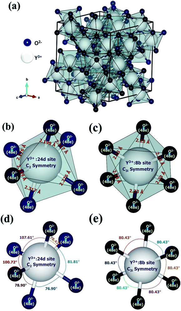 |
| | Fig. 4 Crystal structure of cubic yttrium(III) oxide (Y2O3): (a) unit cell with coordination polyhedra and octahedral coordination with oxygen of cation Y3+. (b) Polyhedron of 24d site with C2 symmetry and interatomic distances are presented in Å. (c) Polyhedron of 8b site with C3i(S6) symmetry and interatomic distances are presented in Å. (d) A ball and stick model of 24d site with C2 symmetry and bond angles are presented in deg. (e) A ball and stick model of 8b site with C3i(S6) symmetry and bond angles are presented in deg. | |
3.1.3. Fourier transform infrared spectroscopy (FTIR). Fig. 5(a) depicts the FTIR spectra of Y2O3:4 at% Eu3+, xLi+ (x = 0.5, 1, 3, 5, 7, 9 at%) nanophosphors. The observed spectra were recorded in the middle infrared region ranges from 4000–400 cm−1 using potassium bromide (KBr) pellet techniques. Fig. 5(b) shows the magnified FTIR spectra of Y2O3:4 at% Eu3+, 7 at% Li+ nanophosphor. The weak absorption band at 3616 cm−1 was detected due to the symmetric O–H stretching vibration (ν) of the (OH) hydroxyl group.23 This is attributed to the H2O molecule, as KBr absorbed the moisture from the air during the pellet preparation or absorbed water by nanophosphors materials from the ambient atmosphere due to its high surface to volume ratio. The strong absorption bands at 1648, 1563, 1410, 1348, and 1262 cm−1 are attributed to C–O stretching vibration (ν) and the bands at 1050, 1018, and 925 cm−1 are attributed to C–O bending vibration (δ), respectively.24 These bands were due to the absorption of CO2 on the surface of the nanophosphors from the ambient atmosphere or residue of carbon in the prepared nanophosphor. It shows that nanomaterials were decomposed completely and no additional hydrogen is remaining there. The weaker metal–oxygen stretching bands observed at 511 and 501 cm−1 were assigned to the Y–O lattice vibration of cubic Y2O3.25 This indicates no other phase or impurities were present in the prepared sample that is pure and crystalline. By the addition of Li+ concentration in the Y2O3:4 at% Eu3+ as a codopant, it enhances the intensity and improves the crystallinity of the sample which was consistent with the XRD results.
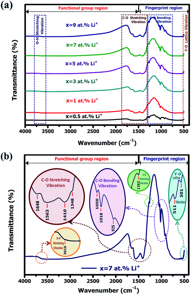 |
| | Fig. 5 (a) FTIR spectra of Y2O3:4 at% Eu3+, xLi+ (x = 0.5, 1, 3, 5, 7, 9 at%) nanophosphors. (b) The magnified FTIR spectra of Y2O3:4 at% Eu3+, 7 at% Li+ nanophosphor. | |
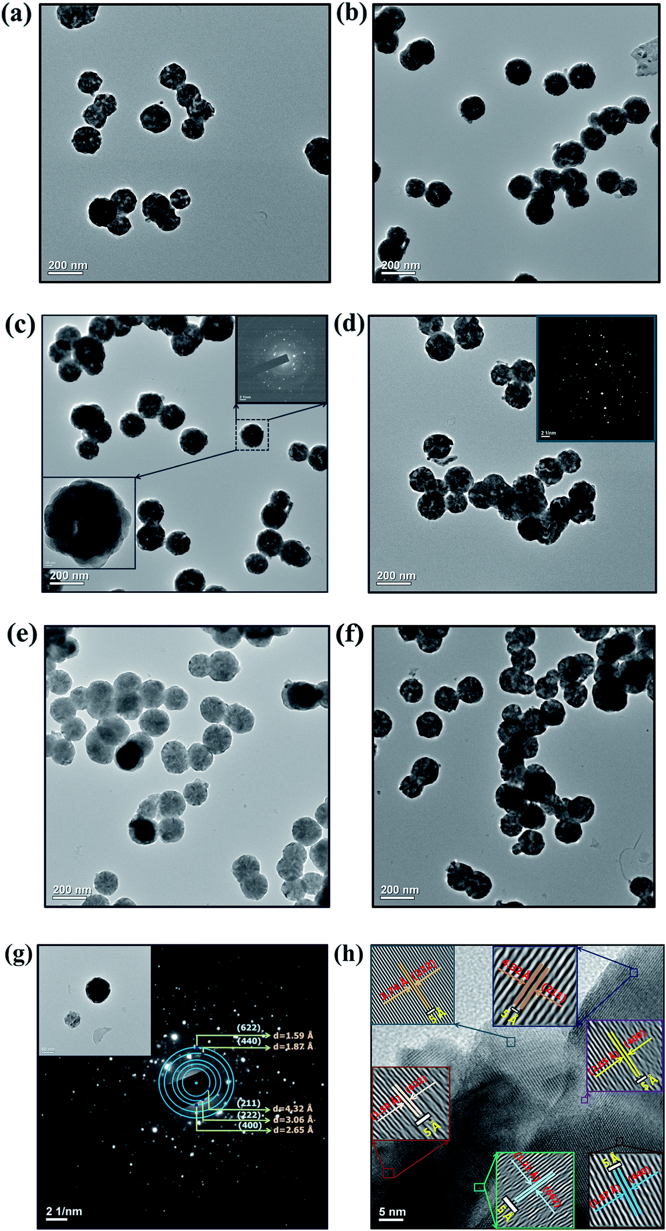
3.1.4. Morphological studies. Fig. 6 shows the typical higher resolution Transmission Electron Micrograph (TEM) of Y2O3:4 at% Eu3+, xLi+ (a) x = 0.5, (b) x = 1 (c) x = 3 (d) x = 5 (e) x = 7 and (f) x = 9 nanophosphors, respectively. The calculated average nanoparticle size estimated from TEM images was around 80 to 90 nm, which is greater than the crystallite size obtained from qualitative XRD analysis and indicating the agglomeration of the sample. By observing the micrograph, it is found that the sizes of nanoparticles were varied with the codoping concentration of Li+ ions and it shows good agreement with XRD analysis. The selected area electron diffraction (SAED) pattern shows multiple diffraction spots ordered in rings, which confirms good crystallization and polycrystalline in the nature of the nanophosphor as shown in Fig. 6(g). The diffraction rings corresponding to (211), (222), (400), (440), and (622) planes were indexed to cubic Y2O3, and is in accordance with the XRD results. The high-resolution TEM image shows clear lattice fringes of the prepared nanophosphor which indicating high crystallinity with polycrystalline in nature of the sample as shown in Fig. 6(h). The lattice fringes shows interplanar spacing of 4.32 Å, 3.74 Å, 2.65 Å, 1.87 Å, 1.89 Å and 1.21 Å consistent with the plane d211 = 4.32 Å, d222 = 3.74 Å, d400 = 2.65 Å, d440 = 1.87 Å, d622 = 1.89 Å and d662 = 1.21 Å values from the ICDD card no. 41-1105 respectively, of the cubic Y2O3 structure.
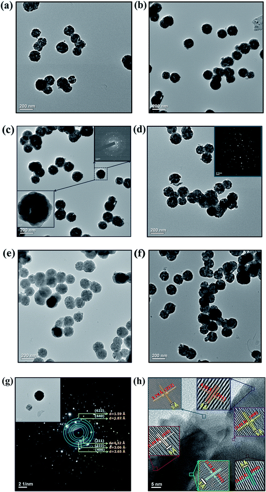 |
| | Fig. 6 HR-TEM Images of Y2O3:4 at% Eu3+, xLi+ (a) x = 0.5 at%, (b) x = 1 at%, (c) x = 3 at%, (d) x = 5 at%, (e) x = 7 at%, (f) x = 9 at% nanophosphors. (g) The magnified HR-TEM image and SAED pattern analysis of x = 9 at% prepared crystalline sample. (h) Lattice fringes of x = 9 at% samples corresponds to cubic yttrium(III) oxide (Y2O3). | |
3.2. Optical characterization
3.2.1. Photoluminescence (PL) study. Fig. 7(a) represents the photoluminescence (PL) excitation spectra of Y2O3:4 at% Eu3+, xLi+ (x = 0.5, 1, 3, 5, 7, 9 at%) nanophosphors. The excitation spectra were obtained by monitoring emission wavelength at 612 nm, corresponding to7F0 → 5D2 transition of Eu3+ which exhibits three broad absorption bands at 254, 393, and 466 nm respectively. The strong band exhibited at 254 nm was due to the charge transfer from 2p orbital of O2− to the 4f orbital of Eu3+ ion in Y2O3:Eu3+.26 The charge transfer transition occurred because the 4f6 configuration of Eu3+ tends to gain an electron from 2p orbital O2− for achieving stable 4f7 half-filled shell configuration.27 The higher two absorption bands at 393, 466 nm were ascribed to the 7F0 → 5L6 and 7F0 → 5D2 transition of Eu3+ ion. On increasing the Li+ co-doping concentration the absorption band intensity reveals increases up to 7 at% and then gradually decreases though further increase of Li+ concentration. This shows that higher co-doping concentration can enhance the excited absorption intensity of the nanophosphor at a certain level. The less intense bands at 299, 305 and 321 nm were also detected in longer wavelength region attributed to 4f6–4f6 transitions of Eu3+ ion.28,29 The increased of absorption intensities probably due to the electron transition to CTB promotes under higher Li+ concentration. When the Li+ is added into the nanocrystals there will be the charge balance and this can be maintained by introducing of oxygen vacancies. By increasing codoping concentration Li+ along with the amount of Li+ ion presence at the substitutional and interstitial sites also increased. This results, increase of crystal defects around the activator lanthanide ions and create the lattice imperfection into the crystal. Thereby, the stark levels in the emission spectrum show the large splitting, which leads to enhance the emission intensity.30 Thus, the absorption intensity of the nanophosphor is enhanced with codoping concentration. Fig. 7(b)–(d) shows photoluminescence emission spectra of Y2O3:4 at% Eu3+, xLi+ (x = 0.5, 1, 3, 5, 7, 9 at%) nanophosphors excited by λex = 254, 393 and 466 nm respectively. Where the impact of Li+ ion on the photoluminescence emission band intensity of prepared nanophosphors are studied in detail. The emission spectra exhibit peaks at ∼534 and 538 nm were attributed to the hypersensitive electric dipole 5D1 → 7F1 transition of Eu3+ ion. This indicates the thermalisation takes place within 5D1 multiplet due to the stark splitting.31,32 The emission band observed at 582 nm was attributed to a 5D0 → 7F0 electric dipole transition,33 which specifies that Eu3+ ion does not occupy in a centrosymmetric site of the host lattice.34 It occupies only C3 and Cs noncentrosymmetric sites of the following symmetries: Cs, C1, C2, C3, C4, C6, C2v, C3v, C4v, and C6v according to electric dipole selection rule.35 The emission band intensity at ∼588, 594, and 600 nm is ascribed to the magnetic dipole transition of 5D0 → 7F1 at 8b crystallographic cation site and S6(C3i) (centrosymmetric) symmetry of Y2O3 (25%) host lattice.36 The most prominent red emission band at 612 nm and a small band at 632 nm were attributed to the 5D0 → 7F2 hypersensitive forced electric dipole transition of Eu3+ ion at 24d crystallographic cation site and C2 (noncentrosymmetric) symmetry of Y2O3 (75%) host lattice.37 This indicates that Eu3+ ions were occupying in two separate positions in the crystallographic lattice. The other weak emission band exhibit at 652 nm corresponding to the electric dipole or quadrupole and the magnetic dipole is a forbidden transition of 5D0 → 7F3, according to Judd–Ofelt theory.38 This is because of J-mixing, where the wave function of 7F3 state mixes with another 7Fj=2,4,6 state.39 These narrow emission bands were revealed due to the shielding effect of 4f electrons by 5s and 5p in the outer shell in the Eu3+ ion.40 By observing all the red emission bands under various excitations were varies with different Li+ co-doping concentration. The emission intensities were enhanced with the increased Li+ concentration up to 7 at% and then gradually decreases though a further increase of Li+ concentration. This is ascribed to the flux effect, improved the crystallinity and growth of the crystallite size caused by the Li+ ion.41 The obtained maximum enhanced intensity of prepared nanophosphor is 4490, 1223.03, 650 (a.u.) concerning excitation wavelengths λex = 254, 393, 466 nm respectively. Where the highest emission intensity band was observed under 254 nm excitation as compare to others. This is due to the charge transfer between O2−–Eu3+ ion. The ionic radius of Li+ is smaller compare to the Eu3+ and Y3+ ion. Thereby it can easily enter the host lattice and can occupy both the substitutional and interstitial sites. When the codoping of Li+ is occupied in lattice sites substitutionally it shows the decrease of emission intensity of Y2O3:Eu3+, Li+ nanophosphor, whereas if Li+ ion occupies in the lattice sites interstitially it shows the enhancement of the emission intensity.42 After entering the interstitial site, Li+ ion can bring the host lattice expansion, thus the variation of lattice constant is occurs. In the case of 0.5, 1, 3, 5, and 9 at% co-doping concentration, Li+ ions dominant substitutional occupation leads to low luminescent intensity. But, in 7 at% codoping concentration, the interstitial occupation of Li+ appears. This causes to enhance the higher luminescence emission intensity at 7 at% than the other concentrations. The enhancement of emission intensity is also indicated the presence of lattice imperfection in the crystal system. An increment of lattice imperfection indicates the increase of oxygen vacancies created by co-dopant Li+ ion. The strong mixing of Li+ ion act as a sensitizer which leads to effective energy transfer in a charge-transfer state by recombining of deeply trapped charges and photogenerated electrons from the conduction band.43 It will decrease luminescence quenching centers at the surface of nanophosphors and increases crystallinity, thereby enhancing the emission band intensity.44,45 With increasing of Li+ concentration the oxygen vacancy also substantially increases, which will demolish the emission intensity. Thereby the increase of emission intensity holds up to 7 at% above this it declines even though Li+ concentration increases further. By comparing all the highest emission band intensity it is found that the most intense emission band excited by 254 nm shows a 6.9 times enhancement than the emission band intensity excited by 393 nm and 3.67 times enhancement than the emission band intensity excited 466 nm. Therefore, the highest intense band may be applicable as a prominent red light emission band for WLEDs fabrication. The second highest emission band intensity under excitation 466 nm shows 1.88 times enhancement than the emission band intensity excited by 393 nm. Thus, it shows that the enhancement of emission band intensity also depends on the variations of excitation wavelength. All these variations of the highest emission intensity plot under various excitation wavelengths are shown in Fig. 7(e) and the calculated ratios are shown in Table 3. The reason for choosing 4 at% Eu3+ doped in Y2O3 nanoparticles is that it shows optimal emission band intensity as compared to other concentration such as 2, 4, 5, 6, 7, 8, 10, 15 and 20 at%, respectively. It exhibited the prominent red emission band at 610 nm due to the 5D0 → 7F2 transition
of Eu3+ ion under 250 nm excitation annealed at 500 °C.14 This indicates the particular concentration based nanophosphor could be a potential candidate to generate the red color for further use as a red component to construct white light color in WLEDs fabrication. Fig. 8(a)–(c) shows the digital photograph of nanophosphor under different excitation wavelength, such as 254, 393 and 466 nm, respectively. Fig. 9(b) represents the energy level diagram for Y2O3:4 at% Eu3+, xLi+ (x = 0.5, 1, 3, 5, 7, 9 at%) nanophosphors. The nanophosphors were excited under three different wavelengths such as 254, 393, and 466 nm respectively. Where the electrons located at ground state (7Fj=0) of Eu3+ ion are promoted to an excited state by absorbing corresponds excitation energy. The excited electrons transfer their location to the 5D1 and 5D0 energy levels by releasing the energy non-radiatively. Finally, the excited electron moves to the ground state by emitting red light under 5D1 → 7F1 and 5D0 → 7Fj=0,1,2,3 transitions of Eu3+ ion. Therefore, it is confirmed that this red-emitting nanophosphor could be a potential candidate for WLEDs fabrication.
 |
| | Fig. 7 (a) PL excitation spectra of Y2O3:4 at% Eu3+, xLi+ (x = 0.5, 1, 3, 5, 7, 9 at%) nanophosphors. PL emission spectra of Y2O3:4 at% Eu3+, xLi+ (x = 0.5, 1, 3, 5, 7, 9 at%) nanophosphors under excitation (b) λexc = 254 nm, (c) λexc = 393 nm and (d) λexc = 466 nm, respectively. (e) PL emission intensity variation of Y2O3:4 at% Eu3+, xLi+ (x = 0.5, 1, 3, 5, 7, 9 at%) nanophosphors under excitation λexc = 254, 393, and 466 nm, respectively. | |
Table 3 Analysis of photoluminescence highest emission intensity variation of Y2O3:4 at% Eu3+, xLi+ (x = 0.5, 1, 3, 5, 7, 9 at%) nanophosphors with respect to various excitation
| Nanophosphor |
Excitation wavelength (nm) |
Emission wavelength (nm) |
Transition |
Maximum intensity (arb. units) |
Ratio (arb. units) |
| Y2O3:4 at% Eu3+, x Li+ |
λex = 254 |
λem = 612 (red) |
5D0 → 7F2 |
4490.00 |
254:393 = 6.90 |
| λex = 393 |
λem = 612 (red) |
5D0 → 7F2 |
650.21 |
254:466 = 3.67 |
| λex = 466 |
λem = 612 (red) |
5D0 → 7F2 |
1223.03 |
466:393 = 1.88 |
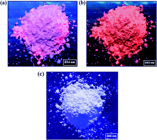 |
| | Fig. 8 Digital photographs of nanophosphor under different excitation wavelength, such as (a) 254 nm (b) 393 nm and (c) 466 nm, respectively. | |
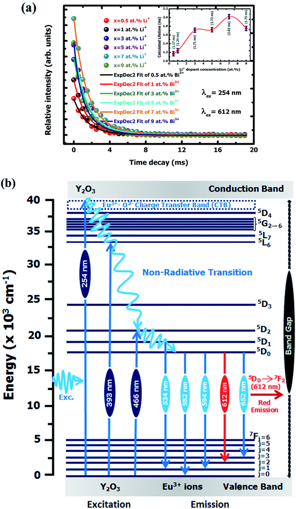 |
| | Fig. 9 (a) PL lifetime decay curves of Y2O3:4 at% Eu3+, xLi+ (x = 0.5, 1, 3, 5, 7, 9 at%) nanophosphors. (b) Schematic energy level diagram for Y2O3:4 at% Eu3+, xLi+ (x = 0.5, 1, 3, 5, 7, 9 at%) nanophosphors. | |
3.2.2 Lifetime study. Fig. 9(a) shows the photoluminescence decay behaviour of 5D0 → 7F2 (λem = 612 nm) transition of Eu3+ for Y2O3:4 at% Eu3+, xLi+ (x = 0.5, 1, 3, 5, 7, 9 at%) nanophosphors excited at 254 nm. All these monitored curves were excellently fitted by a second-order exponential function as follows:46| | |
I(t) = I0 + A1exp(−t/τ1)+ A2exp(−t/τ2)
| (4) |
where I0 and I(t) denoted the luminescence emission intensity at time 0(s), and t(s), respectively, t is time constant, τ1 and τ1 represents the fast and slow decay times for exponential components, A1 and A2 are assigned fitting parameters constants. The fast and slow decay is assigned non-radiative and radiative transition of Eu3+ ion of the nanophosphor. The average lifetimes for the studied nanophosphors were evaluated by using the relation:47| | |
τavg = (A1τ12 + A2τ22)/(A1τ1 + A2τ2)
| (5) |
Thus, the τ1, τ2 and average decay times τavg values of Y2O3:4 at% Eu3+, xLi+ (x = 0.5, 1, 3, 5, 7, 9 at%) nanophosphors are listed in Table 4. It is observed that the average lifetimes of the nanophosphors are varying with the co-doping concentration of Li+ ions. The average lifetimes increase with an increase of Li+ concentration up to x = 7 at% and gained a maximum value of 2.02 ms then slightly decreased though further increase the Li+ concentration. This is because of the flux effect caused by Li+ ion, which improved the high crystallinity of the sample. The Li+ concentration also reduced luminescence-quenching centers at the surface of nanophosphors with improved crystallinity, thereby increases the average lifetime. The addition of different Li+ concentrations also affected the surroundings of Eu3+ ion under 5D0 → 7F2 transition that causes the variation of an average lifetime.
Table 4 Photoluminescence decay lifetime of Y2O3:4 at% Eu3+, xLi+ (x = 0.5, 1, 3, 5, 7, 9 at%) nanophosphors
| Nanophosphor |
Li+-concentration (at%) |
Excitation wavelength (nm) |
Emission wavelength (nm) |
Transition |
τ1 (ms) |
τ2 (ms) |
Lifetime τavg [ms] |
| Y2O3:4 at% Eu3+, x Li+ |
x = 0.5 |
λex = 254 |
λem = 612 (red) |
5D0 → 7F2 |
2.86 |
0.88 |
1.17 |
| x = 1 |
λex = 254 |
λem = 612 (red) |
5D0 → 7F2 |
1.30 |
0.43 |
1.24 |
| x = 3 |
λex = 254 |
λem = 612 (red) |
5D0 → 7F2 |
1.12 |
2.34 |
1.71 |
| x = 5 |
λex = 254 |
λem = 612 (red) |
5D0 → 7F2 |
2.18 |
0.92 |
1.72 |
| x = 7 |
λex = 254 |
λem = 612 (red) |
5D0 → 7F2 |
3.31 |
1.34 |
2.02 |
| x = 9 |
λex = 254 |
λem = 612 (red) |
5D0 → 7F2 |
2.39 |
1.14 |
1.75 |
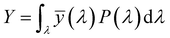
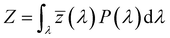
3.2.3. Photometric characterization. The Commission Internationale de l’Eclairage (CIE) 1931 chromaticity diagram has been used to specify the luminescence color of any nanophosphor. The colors are represented as a chromaticity color coordinates (x, y) and correlated color temperature (CCT) in the color space calculated from PL emission spectra through color calculator software. These chromaticity coordinates are calculated by using the three dimensionless color matching functions ![[x with combining macron]](https://www.rsc.org/images/entities/i_char_0078_0304.gif) (λ), ȳ(λ) and
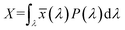
(λ), ȳ(λ) and ![[z with combining macron]](https://www.rsc.org/images/entities/i_char_007a_0304.gif) (λ), respectively.48 The degree of stimulation is used to specified power-spectral density P(λ) and can be obtained by using the three equations:49
(λ), respectively.48 The degree of stimulation is used to specified power-spectral density P(λ) and can be obtained by using the three equations:49| |
 | (6) |
| |
 | (7) |
| |
 | (8) |
where X, Y, and Z are three tristimulus values that provide the stimulation values for standard RGB colors to match the color P(λ). The chromaticity coordinates x, y, and z are calculated from the ratio of the tristimulus values (XYZ) by using the following relations:| |
 | (9) |
| |
 | (10) |
| |
 | (11) |
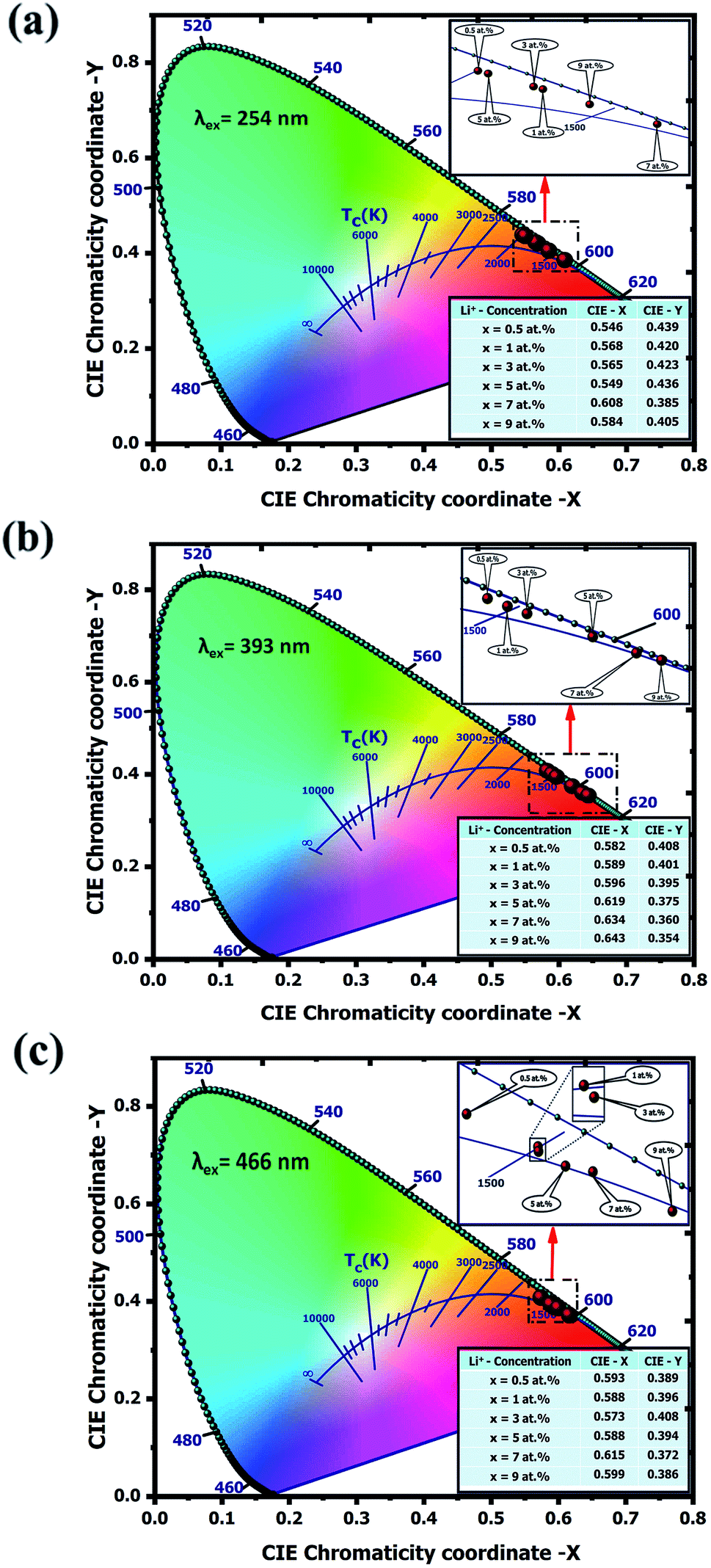
Generally, only two coordinates values of these are independent because x + y + z = 1 regardless of the assigned value of X, Y and Z. Hence CIE 1931 chromaticity diagram selected x and y coordinates to represent the color. Fig. 10 shows the chromaticity diagram for the Y2O3:4 at% Eu3+, xLi+ (x = 0.5, 1, 2, 3, 5, 7 at%) nanophosphors under excitation wavelength (a) 254 nm, (b) 393 nm and (c) 466 nm respectively. The CIE color coordinates (x, y) values of this nanophosphor with various Li+ concentrations have been calculated by using the PL emission spectra data. It is observed from the figure, all the positions of color coordinates under different excitation wavelengths were located in the red region of the color space.
 |
| | Fig. 10 The CIE 1931 chromaticity diagram of Y2O3:4 at% Eu3+, xLi+ (x = 0.5, 1, 3, 5, 7, 9 at%) nanophosphors excited by (a) 254 nm (b) 393 nm and (c) 466 nm, respectively. | |
The quality of the light source has been examined in terms of kelvin (K) based correlated color temperature (CCT) evaluated from chromaticity coordinates. The CCT represents the temperature of a closest Planckian blackbody radiator, whose operating point is closest to the chromaticity point on the CIE chromaticity diagram. The CCT values were calculated using McCamy's empirical formula:50
| | |
CCT = 449n3 + 3525n2 + 6823.3n + 5520.33
| (12) |
where
n = (
x −
xe)/(
ye −
y) is an inverse slope line, (
x,
y) represents the color coordinates and the
xe = 0.332 and
ye = 0.185 are chromaticity epicentre. The calculated CCT values under different excitation wavelengths were found to vary within the range of 1620.24 K to 2117.04 K which belongs in the red region. The variation of CCTs is observed due to the different Li
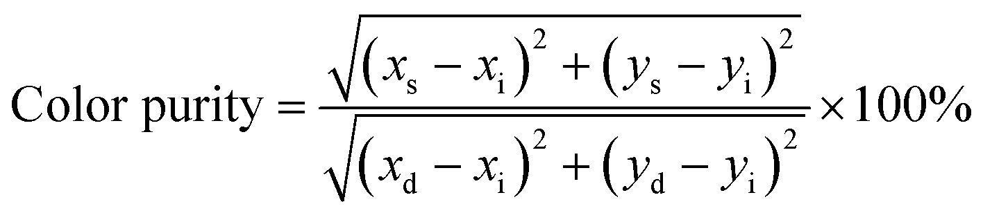
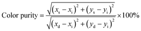
+ codoping concentrations. Apart from color coordinates, color purity also expressed the colorific behavior of emitted light and can be estimated using the following relation:
51| |
 | (13) |
where (
xs,
ys) are the color coordinates of a studied sample, (
xd,
yd) are the color coordinates of the dominant wavelength calculated from the intersection point of the connecting line with spectrum locus which is drawn from the white point through a color representing coordinates point of the chromaticity diagram and (
xi = 0.333,
yi = 0.333) are the color coordinates of the CIE white illuminant point. Based on the
eqn (13) the color purity of synthesized phosphors were found to be more than 91% which indicates Li
+ codoped Y
2O
3:4 at% Eu
3+ nanophosphor is one of the important candidates to produced red emission. The calculated chromaticity color coordinates, CCT, and color purity values of prepared nanophosphors are listed in
Table 5. Hence, the detailed analysis of the nanophosphor affirms that the prepared materials are more suitable for the fabrications of the white light-emitting diode as the red-emitting nanophosphor.
Table 5 The CIE parameters of Y2O3:4 at% Eu3+, xLi+ (x = 0.5, 1, 3, 5, 7, 9 at%) nanophosphors excited by 254, 393 and 466 nm, respectively
| Nanophosphor |
Excitation wavelength (nm) |
Li+-concentration (at%) |
CIE-chromaticity coordinates |
CCT (K) |
Color purity (%) |
CIE color |
| X |
Y |
| Y2O3:4 at% Eu3+, x Li+ |
λex = 254 |
x = 0.5 |
0.546 |
0.439 |
2000.36 |
95.58 |
Red |
| x = 1 |
0.568 |
0.420 |
1765.30 |
96.96 |
Red |
| x = 3 |
0.565 |
0.423 |
1793.56 |
98.18 |
Red |
| x = 5 |
0.549 |
0.436 |
1961.10 |
96.11 |
Red |
| x = 7 |
0.608 |
0.385 |
1639.12 |
98.56 |
Red |
| x = 9 |
0.584 |
0.405 |
1652.62 |
96.98 |
Red |
| Y2O3:4 at% Eu3+, x Li+ |
λex = 393 |
x = 0.5 |
0.582 |
0.408 |
1666.08 |
96.59 |
Red |
| x = 1 |
0.589 |
0.401 |
1634.31 |
97.20 |
Red |
| x = 3 |
0.596 |
0.395 |
1620.95 |
97.83 |
Red |
| x = 5 |
0.619 |
0.375 |
1713.88 |
98.89 |
Red |
| x = 7 |
0.634 |
0.360 |
1946.06 |
98.11 |
Red |
| x = 9 |
0.643 |
0.354 |
2117.04 |
99.65 |
Red |
| Y2O3:4 at% Eu3+, x Li+ |
λex = 466 |
x = 0.5 |
0.593 |
0.389 |
1620.24 |
100 |
Red |
| x = 1 |
0.588 |
0.396 |
1627.74 |
96.39 |
Red |
| x = 3 |
0.573 |
0.408 |
1693.05 |
92.37 |
Red |
| x = 5 |
0.588 |
0.394 |
1625.19 |
93.39 |
Red |
| x = 7 |
0.615 |
0.372 |
1716.13 |
100 |
Red |
| x = 9 |
0.599 |
0.386 |
1625.01 |
91.60 |
Red |
4. Conclusions
In summary, we have presented the effect of Li+ on tunable Y2O3:4 at% Eu3+ red-emitting nanophosphors by structural and luminescence study. The X-ray diffraction pattern shows the formation of pure body-centered cubic phase of Y2O3 with Ia (Number 206, Z = 16) space group without impurity peaks and which confirms there is no effect of Li+ ion on it. The crystallite size was found to be in the range of 50–55 nm calculated by the Debye–Scherrer formula. The quantitative Rietveld refinement exhibited the nanophosphor has a body-centered cubic (I) phase with point group symmetry m. Higher resolution TEM and FTIR study confirm the nanophosphors are good crystallinity with polycrystalline in nature. The PL emission intensity is found greatly depends on the concentration of Li+ ion. With increasing the Li+ concentration the emission intensities are enhanced up to 7 at% and then declines with the further increase of Li+ concentration is due to the flux effect. The most intense emission band was observed at 612 nm ascribed to the 5D0 → 7F2 transition of Eu3+ ion upon 254, 393, and 465 nm excitations. The emission band excited at 254 nm shows the highest enhancement than the other that is 6.9 times higher enhances than the emission intensity excited by 393 nm and 3.67 times enhances than the emission intensity excited by excited 466 nm respectively. The highly enhanced luminescence intensity is due to the flux effect of improved crystallinity, variations in the concentration of oxygen vacancy, and increases in optical volume caused by Li+ ion. Besides, Li+ ion can improve the average lifetime of 5D0 → 7F2 transition, which may be the cause of variation of sensitizer concentration and the radiative transition rate. The CIE chromaticity diagram shows the position of calculated color coordinates; CCTs under different excitation wavelengths were located in the red region. Hence, all the results indicate that Y2O3:4 at% Eu3+, xLi+ (x = 0.5, 1, 2, 3, 5, 7 at%) nanophosphors can be used as a red-emitting nanophosphor for WLEDs applications.
Conflicts of interest
The author declares there is no conflicts of interest in the current research.
Acknowledgements
The authors gratefully acknowledge UGC-DAE CSR, Indore for financial support under (Grant No. CSR/ACCTTS/2017-18/271) of this research work.
References
- M. I. Martinez-Rubio, T. G. Ireland, G. R. Fern, J. Silver and M. J. Snowden, Langmuir, 2001, 17, 7145–7149 CrossRef CAS.
- W.-C. Chien, Y.-Y. Yu and C.-C. Yang, Mater. Des., 2010, 31, 1737–1741 CrossRef CAS.
- J. H. Zhang, Z. D. Hao, J. Li, X. Zhang, Y. Luo and G. Pan, Light: Sci. Appl., 2015, 4, 239–244 CrossRef.
- A. M. Khachatourian, F. Golestani-Fard, H. Sarpoolaky, C. Vogt, E. Vasileva, M. Mensi, S. Popov and M. S. Toprak, J. Lumin., 2016, 169, 1–8 CrossRef CAS.
- C. Liang, X. Huang and W. Huang, J. Mater. Sci.: Mater. Electron., 2018, 29, 11271–11279 CrossRef CAS.
- Q. Zhang, X. Wang, X. Ding and Y. Wang, Inorg. Chem., 2017, 56, 6990–6998 CrossRef CAS.
- Z. Sun, Y. Zhou and M. Li, J. Mater. Res., 2008, 23, 732–736 CrossRef CAS.
- M. Peng, X. Yin, P. A. Tanner, C. Liang, P. Li, Q. Zhang and J. Qui, J. Am. Ceram. Soc., 2013, 96, 2870–2876 CrossRef CAS.
- L. Wang, N. Liao, L. Shi, H. Jia, P. Du, N. Wang, Z. Xi and D. Jin, Electrochem. Solid-State Lett., 2010, 13, E19–E21 CrossRef CAS.
- L. Yongquing, Z. Lingyun, D. Zhenxiang, Z. Ganhong, Z. Yanan and M. Yongquing, Rare Met. Mater. Eng., 2017, 46, 1524–1529 CrossRef.
- A. Pramanik, S. Biswas, C. S. Tiwary, P. Kumbhakar, R. Sarkar and P. Kumbhakar, J. Colloid Interface Sci., 2020, 565, 326–336 CrossRef CAS.
- Q. Wang, Y. Gao, B. Wang, Y. Guo, U. Ahmad, Y. Wang, Y. Wang, S. Lu, H. Li and G. Zhou, J. Mater. Chem. C, 2020, 8, 4343–4349 RSC.
- S. Sadeghi, S. K. Abkenar, C. W. Ow-Yang and S. Nizamoglu, Sci. Rep., 2019, 9, 10061 CrossRef.
- L. R. Singh, R. S. Ningthoujam, V. Sudarsan, I. Srivastava, S. D. Singh, G. K. Dey and S. K. Kulshrestha, Nanotechnology, 2008, 19, 055201 CrossRef.
- H. M. Rietveld, J. Appl. Crystallogr., 1969, 2, 65–75 CrossRef CAS.
- J. Rodríguez-Carvajal, FULLPROF: A Rietveld refinement pattern matching analysis program, Laboratory Léon Brillouin (CEA-CNRS): Gif-sur-Yvette Cedex, France, 2011, https://www.ill.eu/sites/fullprof/ Search PubMed.
- S. T. Tan, B. J. Chen, X. W. Sun, W. J. Fan, H. S. Kwok, X. H. Zhang and S. J. Chua, J. Appl. Phys., 2005, 98, 013505 CrossRef.
- G. K. Williamson and W. H. Hall, Acta Metall., 1953, 1, 22–31 CrossRef CAS.
- U. Pal, D. Samantha, S. Ghorai and A. K. Chaudhuri, J. Appl. Phys., 1993, 74, 6368–6374 CrossRef CAS.
- B. D. Cullity, Elements of X-ray Diffraction, Addison-Wesley Publishing Company, Inc., Reading, MA, 1978, 2nd edn Search PubMed.
- M. Ferrari and L. Lutterotti, J. Appl. Phys., 1994, 76, 7246–7255 CrossRef CAS.
- K. Momma and F. Izumi, VESTA: a three-dimensional visualization system for electronic and structural Analysis, J. Appl. Crystallogr., 2008, 41, 653–658 CrossRef CAS.
- R. S. Ukare, G. D. Zade, B. Deva Prasad Raju and S. J. Dhoble, Optik, 2016, 127, 1871–1878 CrossRef CAS.
- D. Kumar, M. Sharma and O. P. Pandey, Opt. Mater., 2014, 36, 1131–1138 CrossRef CAS.
- R. Hari Krishna, B. M. Nagabhushana, H. Nagabhusana, N. Suriya Murthy, S. C. Sharma, C. Shivakumara and R. P. S. Chakradhar, J. Phys. Chem. C, 2013, 117, 1915–1924 CrossRef.
- X. Bai, H. Song, L. Yu, L. Yang, Z. Liu, G. Pan, S. Lu, X. Ren, Y. Lei and L. Fan, J. Phys. Chem. B, 2005, 109, 15236–15242 CrossRef CAS.
- Z. G. Wei, L. D. Sun, C. S. Liao, X. C. Jiang, C. H. Yan, Y. Tao, X. Y. Hou and X. Ju, J. Appl. Phys., 2003, 93, 9783–9788 CrossRef CAS.
- G. Jia, H. You, Y. Song, Y. Huang, M. Yang and H. Zhang, Inorg. Chem., 2010, 49, 7721–7725 CrossRef CAS.
- J. Yang, Z. Quan, D. Kong, X. Liu and J. Lin, Cryst. Growth Des., 2007, 7, 730–735 CrossRef CAS.
- N. Dhananjaya, H. Nagabhushana, B. M. Nagabuushana, B. Rudraswamy, C. Shivakumara and R. P. S. Chakradhar, J. Alloys Compd., 2011, 509, 2368–2374 CrossRef CAS.
- A. Ćirić, S. Stojadinović, M. G. Brik and M. D. Dramićanin, Chem. Phys., 2020, 528, 110513 CrossRef.
- A. K. Singh, K. P. O'Donnell, P. R. Edwards, D. Cameron, K. Lorenz, M. J. Kappers, M. Boćkowski, M. Yamaga and R. Prakash, Appl. Phys. Lett., 2017, 111, 241105 CrossRef.
- J. S. Bae, B. K. Moon, J. H. Jeong, S. S. Yi and J. H. Kim, J. Appl. Phys., 2005, 98, 043513 CrossRef.
- F. P. Du, Y. Nakai, T. Tsuboi, Y. L. Huang and H. J. Seo, J. Mater. Chem., 2011, 21, 4669–4678 RSC.
- X. Y. Chen and G. K. Liu, Solid State Chem., 2005, 178, 419–428 CrossRef CAS.
- M. Maitric, B. Antic, M. Balanda, D. Rodic and M. L. Napijalo, J. Phys.: Condens. Matter, 1997, 9, 4103–4111 CrossRef.
- J. Silver, M. I. Martinez-Rubio, T. G. Ireland and R. Withnall, J. Phys. Chem. B, 2001, 105, 7200–7204 CrossRef CAS.
- K. A. Gschneidner and L. R. Eyring, Handbook on the Physics and Chemistry on Rare-Earths; North-Holland Amsterdam, 1997 Search PubMed.
- C. Cascales, J. Fernández and R. Balda, Opt. Express, 2005, 13, 2141–2152 CrossRef CAS.
- X. Li, Q. Li, Z. Xia, L. Wang, W. Yan, J. Wang and R. I. Boughton, Cryst. Growth Des., 2006, 6, 2193–2196 CrossRef CAS.
- N. Liao, L. Shi, H. Jia, X. Yu, D. Jin and L. Wang, Inorg.
Mater., 2010, 46, 1325–1329 CrossRef CAS.
- Y. Yan, W. Zhang, B. Ren, L. Zhong and Y. Xu, Ionics, 2016, 23, 869–875 CrossRef.
- S. Yi, J. S. Bae, B. K. Moon and J. H. Jeong, Appl. Phys. Lett., 2002, 81, 3344–3346 CrossRef CAS.
- J. Y. Cho, Y. R. Do and Y. Huh, Appl. Phys. Lett., 2006, 89, 131915 CrossRef.
- J. S. Bae, J. H. Jeong, K. S. Shim, B. K. Moon, S. Yi, J. H. Kim, Y. S. Kim and J. S. Lee, Appl. Surf. Sci., 2006, 252, 4564–4568 CrossRef CAS.
- C. Liang, X. Huang and W. Huang, J. Mater. Sci.: Mater. Electron., 2018, 29, 11271–11279 CrossRef CAS.
- C. K. Lin, M. L. Pang, M. Yu and J. Lin, J. Lumin., 2005, 114, 299–306 CrossRef CAS.
- Q. Y. Zhang, K. Pita, W. Ye and W. X. Que, Chem. Phys. Lett., 2002, 351, 163–170 CrossRef CAS.
- K. V. Krishnaiah, K. P. Kumar and C. K. Jayasankar, Mater. Express, 2013, 3, 61–70 CrossRef CAS.
- C. S. McCamy, Color Res. Appl., 1992, 17, 142–144 CrossRef.
- Y. C. Fang, S. Y. Chu, P. C. Kao, Y. M. Chuang and Z. L. Zeng, J. Electrochem. Soc., 2011, 158, J1–J5 CrossRef CAS.
|
| This journal is © The Royal Society of Chemistry 2020 |
Click here to see how this site uses Cookies. View our privacy policy here. 
 Open Access Article
 This Open Access Article is licensed under a Creative Commons Attribution-Non Commercial 3.0 Unported Licence
 a,
Laishram Robindro Singh
a,
Laishram Robindro Singh