
 Open Access Article
 This Open Access Article is licensed under a Creative Commons Attribution-Non Commercial 3.0 Unported Licence
Nucleation and growth behavior of Er3+ doped oxyfluorophosphate glasses
N. Ojha *a,
A. Szczodraa,
N. G. Boettib,
J. Masserac and
L. Petita
*a,
A. Szczodraa,
N. G. Boettib,
J. Masserac and
L. Petita
aPhotonics Laboratory, Tampere University, Korkeakoulunkatu 3, FI-33720 Tampere, Finland. E-mail: nirajan.ojha@tuni.fi
bFondazione LINKS – Leading Innovation & Knowledge for Society, Via P. C. Boggio 61, 10138 Torino, Italy
cFaculty of Medicine and Health Technology, Tampere University, Korkeakoulunkatu 3, FI-33720 Tampere, Finland
First published on 7th July 2020
Abstract
The nucleation and growth behavior of glasses with the composition (75 NaPO3-25 CaF2)100−x–(TiO2/ZnO/MgO)x, with x = 0 and x = 1.5 (in mol%) is investigated. The glasses possess similar activation energy for crystallization and Johnson–Mehl–Avrami exponent, with value 2 confirming bulk crystallization of crystals with needle like shape. The Ti and Mg glasses exhibit broader nucleation curve and higher Tn max than the x = 0 and Zn glasses due to their stronger field strength. The crystal growth rates were determined and validated using SEM. Finally, we showed that the nucleation and growth of glasses can be controlled due to the large difference between onset of crystallization and maximum nucleation temperature which is crucial when preparing novel transparent glass-ceramics.
Introduction
Addition of rare-earth (RE) ions in glasses has been of great interest for a wide range of applications in the field of telecommunications, light detection and ranging (LIDAR), solar panels, color sensing, biomedical diagnostics, just to name a few.1–3 Among the rare earth ions, Er3+ ions have been in the limelight due to their large number of energy levels and especially due to the transition from 4I13/2 to 4I15/2 levels which corresponds to the emission at 1530 nm that makes Er3+ doped glasses useful for eye-safe laser and optical telecommunications of the third window.4,5 Oxyfluorophosphate glasses in particular are promising glasses for the fabrication of new lasing glasses as these glasses combine the properties of both oxides and fluorides. These glasses possess good chemical durability, thermal stability, mechanical strength and high rare earth ion solubility.6 Additionally, these oxyfluorophosphate glasses can be engineered with low melting point and so they can be prepared quite easily as compared to their silica counterparts.Nowadays, glass-ceramics (GCs) are gaining much more attention due to their widespread applications in optical, laser and biomedical fields to name a few.7 Stookey discovered the first GCs in 1960 where he defined them as special glasses that contains nucleating agent and controlled crystallization.8 Transparent RE doped GCs which contain crystals homogeneously distributed in the volume of the glass matrix are considered promising materials for a variety of additional applications such as optical amplifiers, optical electronic chips, luminescence labels and 3D displays.9 Indeed, these glass-ceramics exhibit larger absorption and emission cross-sections and energy transfer rates compared to their glassy counterparts when the desirable crystalline phases are generated around the rare earth ions or transition metal ions.10,11 Auzel et al.12 successfully prepared a partially crystalline material having luminescence efficiency double than that of LaF3:Er3+, Yb3+ phosphor using lead fluoride and several glass forming oxides. However, those materials lacked transparency due to the presence of large crystals (∼10 μm). For the GCs to be transparent, the crystals need to have a size smaller than the incident light wavelength.13 Therefore, the size and size distribution of the crystals as well as the refractive index difference between the crystals and the glass should be tailored in order to minimize light scattering. One of the first transparent glass-ceramics was successfully prepared with crystalline PbxCd1−xF2 cubic fluoride phase doped with Er3+ and Yb3+ ions in ref. 14. Since this achievement, great effort has been made on the preparation of novel transparent GCs within different glass systems such as silicate,15–19 tellurite,20–23 germanate24–27 and phosphate,28–31 just to cite few examples.
When developing novel GCs, it is therefore crucial to understand the formation of crystals inside the glass matrix in order to control their size and size distribution in the amorphous network. The GCs are usually fabricated using a three (3) step process: at first, a glass is obtained. Then, the glass is heat treated at a specific temperature called the nucleation temperature to form the nuclei and finally heat treated at higher temperature in order to grow the nuclei into crystals. This process can result in a glass having crystals that are relatively uniform in size and dispersed homogeneously within the glassy matrix.32 The crystallization is typically defined by the activation energy for crystallization, which is related to the temperature dependence of the crystallization process and by the Johnson–Mehl–Avrami (JMA) exponent, which provides the information on the crystal growth dimensionality.33–35 It is also important to estimate the growth rate of the crystals as a function of the heat treatment temperature, in order to fabricate transparent GCs.
In our previous study,36 Er3+ doped glasses with the composition (75NaPO3–(25 − x)CaO–xCaF2) were prepared and heat treated. We showed that the transparent GC can be obtained from the glass with x = 25. CaF2 crystals were found in the volume of the glass and doped with Er3+.37
In this study, we present a complete study on the nucleation and growth behavior of the glass with x = 25. We also investigate the impact of the addition of TiO2, MgO and ZnO in this glass on the precipitation of the Er3+ doped CaF2 crystals in the volume of the glass during heat treatment. We report first the study of the impact of the glass composition on the thermal, optical, structural and luminescence properties of the newly developed glasses. The activation energy for crystallization, the Johnson–Mehl–Avrami exponent, the nucleation-like curves and the growth rates of the glasses are presented and discussed as a function of the glass composition.
Experimental
Oxyfluorophosphate glasses with the composition (100-x-0.25) (75NaPO3–25CaF2) – x(TiO2/ZnO/MgO) (in mol%), doped with 0.25 mol% Er2O3, with x = 0 and x = 1.5 were prepared using standard melting procedure in air using platinum crucible. The glass with x = 0 is labelled as Ref and the glasses prepared with 1.5 mol% TiO2 as Ti glass, with 1.5 mol% ZnO as Zn glass and with 1.5 mol% MgO as Mg glass. The chemicals used for the glass preparation were NaPO3 (Alfa-Aesar, technical grade), CaF2 (Honeywell-Fluka, 99%), Er2O3 (Sigma-Aldrich, 99.9%), MgO (Honeywell, ≥99%), TiO2 (Sigma-Aldrich, 99.8%) and ZnO (Sigma-Aldrich, 99.99%). The glasses were melted for 5 minutes between 900 and 1025 °C depending on the composition of the glass. After melting, the glasses were quenched and annealed for 6 h at 40 °C below their respective glass transition temperature to release the stress from the quench. The glasses were polished and finally heat treated for 17 h at 20 °C above their glass transition temperature Tg and then at ∼Tp for upto 6 hours.The glass transition temperature (Tg) as well as the onset of the crystallization (Tx) and the crystallization temperature (Tp) of the glasses were determined by differential thermal analysis (DTA) (TA instruments SDT Q600) using various heating rates (5°, 10°, 15°, and 20 °C min−1) using glasses crushed into powder with a 125–250 μm particles size. The measurements were performed using platinum pans in N2 atmosphere. The glass transition temperature was taken at the inflection point of the endotherm, as obtained by taking the minima of first derivative of the DTA curve. Tp was taken at the maximum of the exothermic peak and Tx at the onset of the crystallization peak. All measurements were performed with an accuracy of ±3 °C.
Electron Probe MicroAnalyzer (EPMA) (CAMECA, SX100) equipped with 5 wavelength dispersive X-ray analyzers (WDX) was used to determine the fluorine content with an accuracy of ±0.1 at%. The EPMA was operated at 15 keV and 40 nA. Quantitative analyses were performed using the Cameca QUANTITOOL analytical programme, calibrated with ErF3 reference standard, applying a PAP matrix correction. A scanning electron microscope (Carl Zeiss Crossbeam 540) equipped with Oxford Instruments X-MaxN 80 EDS detector was used to image and analyse the composition of the crystals. The error of composition is ±1.5 mol%. For the EPMA and SEM analysis, the glasses and GCs were polished and coated with a carbon layer to prevent charging.
The activation energy for crystallization (Ec) was determined by measuring Tp at different heating rates of powdered sample of size 125–250 μm and then applying the Kissinger equation:34
 | (1) |
To verify the Kissinger equation, Ec was also determined using the Friedman method using the equation:35
 | (2) |
The Johnson–Mehl–Avrami (JMA) exponent, which is related to the dimensionality of the crystallization (surface vs. bulk crystallization), was determined using the equation proposed by Augis and Bennett:38
 | (3) |
n was also obtained using the Ozawa method from the fraction of glass crystallized at various heating rates at a constant temperature using the following equation:33
 | (4) |
The temperature of maximum nucleation (Tn max) was determined from the nucleation-like curve using the method described by Marotta et al.39 In this method, the glass powder was subjected to an isothermal hold, inside the DTA, at various temperatures T (between Tg and Tx) near the suspected temperature of the maximum nucleation (Tn max). The temperature was then reduced to 200 °C and finally increased to a temperature T, above the crystallization temperature. The nucleation like curve was obtained from the plot of  , (where Tp and
  are the maximum of the exothermal peak with and without the nucleation thermal hold). The maximum of the obtained curve gives Tn max.
The phases present in the heat treated glasses were analyzed using the Panalytical EMPYREAN multipurpose X-ray Diffractometer (XRD) using nickel filtered copper K-Alpha radiation. The spectra were obtained using the Bragg–Brentano geometry and by rotating the sample holder around the Phi-axis at a constant speed of 16 revolutions per minute.
The absorption spectra were measured using a UV-Vis-NIR spectrophotometer (UV-3600 Plus, Shimadzu) from 200 to 1800 nm with 0.5 nm interval. Samples were polished and their thickness were measured using a digital caliper with an accuracy of ±0.05 mm. The absorption cross-section σ (in cm2) was calculated using the following equation:
 | (5) |
The glass samples, crushed into powder, were excited using a TEC-cooled fiber-coupled multimode laser (II–VI Laser Enterprise). The center emission wavelength (λexc) of the laser was ∼975 nm and its incident power at the sample surface was ∼23.5 mW. The resulting normal photoluminescence (PL) and up-conversion spectra were measured using a Spectro 320 optical spectrum analyzer (Instrument Systems Optische Messtechnik GmbH, Germany) at room temperature. The spectrum analyzer was equipped with a photomultiplier tube capable of measuring wavelengths between 350 and 850 nm and an InGaAs detector for wavelengths ranging from 800 to 1700 nm. The luminescence light was collected from the samples to the spectrum analyzer using a lens and a liquid light guide.
The lifetime of the Er3+:4I13/2 energy level was measured using a fiber pigtailed laser diode at 976 nm. The signal was recorded using a digital oscilloscope (Tektronix TDS350) and the decay traces were fitted using single exponential. The detector used for this measurement was a Thorlabs PDA10CS-EC. The accuracy of the measurement was ±0.20 ms.
The IR spectra of the powder glasses were measured using a Perkin Elmer Spectrum FTIR2000 spectrometer with Attenuated Total Reflection (ATR) mode between 600 and 2000 cm−1 with a resolution of 2 cm−1 and 8 scan accumulation.
Results and discussion
The thermal and physical properties of the glasses are shown in Table 1. DTA thermogram of the investigated glasses can be seen in Fig. 1. The changes in the glass composition leads to a slight increase in the density, Tg, Tx and Tp, the addition of TiO2 being the most effective in these changes. As seen in Table 1, the increase in the melting temperature decreases the F at% in the glass as measured using EPMA in agreement with our previous study.19 Therefore, the increase in Tg may be related to the different F at% in the glasses but it may also indicate that the changes in the glass composition increases the strength of the network and the bond strength as reported in ref. 40. The changes in the glass composition increases slightly ΔT (ΔT = Tx − Tg) confirming that the addition Ti, Mg or Zn can be used to increase slightly the resistance of the glass towards crystallization. However, one should point out the ΔT of the investigated glasses still remains lower than 90 °C.| Glass label | Quantification using EPMA/WDX | Tm (°C) | ρ ± 0.02 (g cm−3) | Tg ± 3 (°C) | Tx ± 3 (°C) | Tp ± 3 (°C) | ΔT ± 6 (°C) | |
|---|---|---|---|---|---|---|---|---|
| Expected F at% | Measured F at% (±0.1 at%) | |||||||
| Ref | 11.1 | 9.2 | 900 | 2.63 | 269 | 323 | 338 | 54 |
| Ti | 11.0 | 8.9 | 1025 | 2.65 | 286 | 350 | 370 | 64 |
| Mg | 9.4 | 900 | 2.66 | 279 | 345 | 365 | 66 | |
| Zn | 9.1 | 1000 | 2.65 | 276 | 334 | 350 | 58 | |
 | ||
| Fig. 1 DTA thermogram of the investigated glasses. | ||
The IR spectra of the glasses are presented in Fig. 2. They are normalized to the main band at ∼1130 cm−1. Consequently, the intensity changes are expressed relatively to the main band. The IR spectra of the new glasses are similar to those reported in ref. 36 where a detailed attribution of the bands can be found. The addition of ZnO and MgO leads to a small decrease in intensity of the bands at about 700, 950, ∼1000 and 1250 cm−1 and to a slight increase in the intensity of the shoulder at 1100 cm−1 as compared to the main band whereas the addition of TiO2 increases the intensity of the bands at around 880 and 950 cm−1 and decreases the intensity of the band at 1250 cm−1. One can also notice that the position of the bands at 880 and 1250 cm−1 shifts towards smaller wavenumbers when adding TiO2 due to the strong field strength of the Ti ions. These changes in the IR spectra can be related to a decrease in the Q2 units and to an increase in Q1 units as expected from the change in the O/P ratio when adding ZnO, MgO and TiO2.41 In agreement with,42 Mg, Ti and Zn are expected to cross-link the phosphate chains by creating P–O–Mg/Ti/Zn bonds at the expense of P–O–P bonds associated with a reduction in the number of Q2 units.41,43 Therefore, the addition of ZnO, MgO and TiO2 is suspected to cause distortion of the glass network which is in agreement with the increase in Tg seen in Table 1. Similar results were reported in ref. 44. Due to the higher field strength of Mg compared to Zn,45 the changes in the IR spectra are more visible when adding MgO than ZnO in the network.
 | ||
| Fig. 2 Normalized IR spectra of the investigated glasses. | ||
The absorption spectra and the normalized absorption spectra are shown in Fig. 3a and b respectively. As seen in Fig. 3a, the addition of TiO2 leads to a shift of the band gap to longer wavelength most probably due to the presence of Ti3+ according to ref. 46. The change in the position of the band gap can also be related to the formation of Ti–O–P bonds as discussed earlier. Due to the decrease in the connectivity of the phosphate network, the bandgap is shifted to longer wavelengths when adding MgO and ZnO, the shift being more visible when adding MgO. The shape of the absorption band centered at ∼1532 nm is similar in all glasses (Fig. 3b).
 | ||
| Fig. 3 Absorption spectra (a) and normalized absorption band at 1500 nm (b) of the investigated glasses. | ||
The absorption coefficients and the absorption cross-sections at 975 and 1532 nm are presented in Table 2. Within the accuracy of the measurement, the changes in the glass composition have no impact on the absorption cross-sections at those wavelengths. Therefore, the site of the Er3+ ions is suspected not to be strongly impacted by the changes in the glass composition; Ti, Mg and Zn are not suspected to participate to the second coordination shell around Er3+.
| Glass label | Er3+ ions/cm3 (1019) ± 5% | αabs at 975 nm (cm−1) | σAbs at 975 nm (10−21 cm2) ± 10% | αabs at 1532 nm (cm−1) | σAbs at 1532 nm (10−21 cm2) ± 10% |
|---|---|---|---|---|---|
| Ref | 8.19 | 0.16 | 2.01 | 0.52 | 6.32 |
| Ti | 8.27 | 0.19 | 2.34 | 0.52 | 6.23 |
| Mg | 8.35 | 0.15 | 1.82 | 0.47 | 5.61 |
| Zn | 8.27 | 0.18 | 2.16 | 0.53 | 6.41 |
The spectra presented in Fig. 4a exhibit the typical broadband Er3+ emission (4I13/2 → 4I15/2) in glasses.3 The glasses exhibit similar intensity (within ± 10%) and shape of the emission centered at 1.5 μm confirming that Ti, Mg and Zn have no noticeable impact on the site of the Er3+ ions. Similarly, the relative intensity of the upconversion was found not to be affected by the change in the composition (within 10%). As seen in Fig. 4b, the upconversion spectra exhibit the typical green and red emissions from Er3+ ions in amorphous site after pumping at 975 nm. These green and red emissions correspond to 2H11/2 (525 nm) 4S3/2 (550 nm) → 4I15/2 and 4F9/2 → 4I15/2 transitions of Er3+, respectively.47 No noticeable changes can be seen in the shape of the emission band at 550 nm, which can be associated to a hypersensitive transition48 with the changes in the glass composition confirming that the site of the Er3+ ions is not strongly modified by the addition of TiO2, MgO and ZnO. The addition of ZnO has no impact on the ratio of the intensity of the green to red emissions while the intensity of the red emission increases slightly as compared to the green emission when adding TiO2 and MgO probably due to their strong field strength.
 | ||
| Fig. 4 Normalized emission spectra centered at 1.5 μm (a) and normalized upconversion spectra (b) of the investigated glasses (λexc = 975 nm). | ||
The lifetime values of the Er3+:4I13/2 level in the investigated glasses are listed in Table 3. Within the accuracy of the measurement, the change in the glass composition has no impact on the lifetime value confirming that the sites of Er3+ ions are similar in the glasses. One should point out that the lifetime values are similar to those reported in ref. 37 but longer than the lifetime values reported inref. 36 although the Er2O3 concentration is larger in the investigated glasses than in ref. 36. It is possible that the glasses used in ref. 36 contain a larger amount of OH groups, known as quenchers of Er3+ ions luminescence,49,50 than the glasses used in this study and in ref. 37.
| Glass label | As-prepared glasses | Duration of the heat treatment at Tp for | ||
|---|---|---|---|---|
| 1 h | 3 h | 6 h | ||
| Ref | 8.2 | 8.9 | 8.9 | 8.8 |
| Ti | 8.4 | 8.7 | 8.6 | 8.9 |
| Mg | 8.2 | 8.7 | 8.6 | 8.7 |
| Zn | 8.3 | 8.6 | 8.8 | 8.7 |
As performed in ref. 36 and 37, the glasses were heat treated at Tg + 20 °C for 17 h and then at Tp for 1 to 6 h. The glasses were polished prior to the heat treatment and were heat treated in air on a Pt foil to avoid contamination from the sample holder. The pictures of the glasses prior to and after heat treatment are presented in Fig. 5. All the investigated glasses exhibit bulk crystallization. The Ref and the Zn glasses are still transparent while the Ti and Mg glasses become opaque after 6 h at Tp.
 | ||
| Fig. 5 Pictures of the glasses heat treated at Tg + 20 °C for 17 h and at Tp for 1, 3 and 6 hours. | ||
The transmittance spectra of the glasses prior to and after heat treatment are presented in Fig. 6. They clearly show losses in the transparency of the glasses after heat treatment especially for the Ti and Mg glasses. The large decrease in the transmittance of the Ti and Mg glasses can be related to the presence of a larger amount of crystals and/or larger crystals inside these glass matrices than in the Ref and Zn glass matrices causing stronger scattering.51
 | ||
| Fig. 6 Transmittance spectra of the Ref (a), Ti (b), Mg (c) and Zn (d) glasses heat treated at Tg + 20 °C for 17 h and at Tp for 1, 3 and 6 hours (thickness of the glasses was ∼1mm). | ||
The XRD pattern of these HT glass were measured to verify if CaF2 crystals precipitate in all glasses during heat treatment. The XRD pattern of the glasses prior to and after heat treatment are shown in Fig. 7.
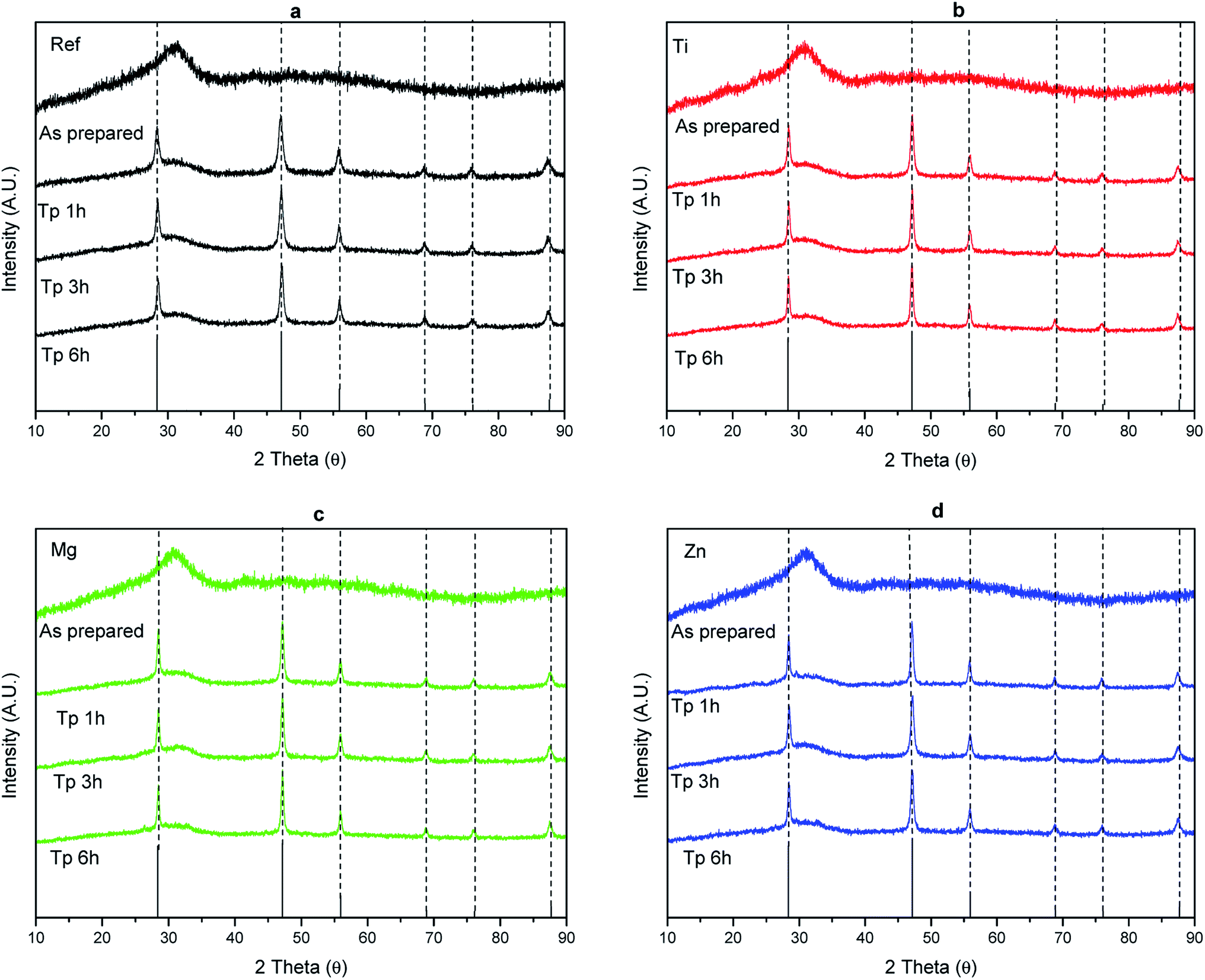 | ||
| Fig. 7 XRD patterns of the Ref (a), Ti (b), Mg (c) and Zn (d) glasses prior to and after heat treatment Tg + 20 °C for 17 h and at Tp for 1, 3 and 6 hours. | ||
The XRD pattern of the as-prepared glasses exhibit a broad band confirming that the as-prepared glasses are amorphous prior to the heat treatment. The XRD patterns of the heat treated glasses show sharp peaks which correspond to the precipitation of CaF2 (ICDD PDF #00-035-0816) indicating that the change in the glass composition has no impact on the crystal phase precipitating in the glass. The size of the CaF2 crystallites can be estimated from the XRD pattern using the Scherrer's equation:52
D = Kλ/β![[thin space (1/6-em)]](https://www.rsc.org/images/entities/char_2009.gif) cosθ cosθ
| (6) |
The Table 4 summarizes the mean crystalline sizes of CaF2 crystals in the heat treated glasses.
| Glass label | Heat treated at Tg + 20 °C for 17 h and then at Tp for 1 h | Heat treated at Tg + 20 °C for 17 h and then at Tp for 3 h | Heat treated at Tg + 20 °C for 17 h and then at Tp for 6 h |
|---|---|---|---|
| Ref | 17 | 19 | 19 |
| Ti | 24 | 31 | 56 |
| Mg | 24 | 24 | 38 |
| Zn | 14 | 17 | 20 |
As seen in Table 4, the large decrease in the transmittance observed in the Ti and Mg glasses (Fig. 6) is probably due to the presence of large crystals of CaF2 in the glasses. It is interesting to point out that the mean crystalline size of the CaF2 crystals in the Ti and Mg glasses seems to be highly dependent on the duration of the heat treatment while the CaF2 crystals are expected to grow slower in the Ref and Zn glasses when heat treated at their respective Tp. The crystal volume fraction was estimated by calculating the ratio of integrating area of the peaks to total integrated area of the XRD patterns as in ref. 15, 53 and was found to be about (3.4 ± 0.1)%, independently of the glass composition. One should point out that this crystal volume fraction is small compared to other glass-ceramics.15
Similar to previous report,36 a decrease in the intensity of the emission centered at 1.5 μm and an increase in the intensity of the upconversion and in the lifetime values of the Er3+:4I13/2 level (Table 3) were observed after heat treating all the investigated glasses. We also noticed for all the investigated glasses that the shape of the emission centered at 1.5 μm and of the green emission, known to be a hypersensitive transition and so sensitive to changes in the environment of Er3+ ions, changed post heat treatment (Fig. 8 and 9) confirming that the CaF2 crystals precipitating in all the investigated glasses contain Er3+ ions. One should point out that no noticeable impact of the glass composition on the reduction of the intensity of the emission at 1.5 μm and on the increase of the upconversion intensity (within ± 10%) was seen indicating that the glass composition has no significant impact on the sites of the Er3+ ions; Er3+ ions are suspected to be located in similar (amorphous and CaF2) sites in the investigated glasses.
 | ||
| Fig. 8 Normalized emission spectra of the Ref (a), Ti (b), Mg (c), and Zn (d) glasses prior to and after heat treatment at (Tg + 20 °C) for 17 h and then at different temperatures and durations. Spectra were obtained using λexc = 975 nm. | ||
 | ||
| Fig. 9 Normalized upconversion spectra of the Ref (a), Ti (b), Mg (c), and Zn (d) glasses prior to and after heat treatment at (Tg +20 °C) for 17 h and then at different temperatures and durations. Spectra were obtained using λexc = 975 nm. | ||
In order to better understand the impact of the glass composition on the crystallization process, the activation energy for crystallization (Ec), JMA exponent nucleation curve and crystal growth rate of the glasses were calculated. The activation energy for crystallization of the glasses was calculated using two methods and the Ec's are listed in Table 5. The activation energies reported using the Kissinger method appeared to be similar regardless of the glass composition. The standard deviation in Ec calculated using the Friedman method, for each glass composition, is less than 10% indicating that only one crystallization mechanism is involved throughout the entire crystallization process. The low standard deviation also validates the Kissinger method which is often used to further calculate the JMA exponent. The similarity in Ec between glasses and the low standard deviation measured for each Ec using the Friedman technique tend to indicate that the crystallization process is nucleation and growth and the primary crystal field is similar in all the investigated glasses.34,54
| Glass label | Activation energy (Ec) | JMA exponent (n) | Maximum nucleation temperature Tn max (°C) | Tx − Tn max (°C) | ||
|---|---|---|---|---|---|---|
| Kissinger method ±30 kJ mol−1 | Friedman method kJ mol−1 | Augis–Benett method (±0.1) | Ozawa–Chen method | |||
| Ref | 190 | 182 ± 10 | 2.1 | 2.0 ± 0.5 | 276 ± 5 | 47 ± 8 |
| Ti | 185 | 226 ± 20 | 1.7 | 1.5 ± 0.4 | 295 ± 5 | 55 ± 8 |
| Mg | 158 | 186 ± 11 | 1.8 | 1.6 ± 0.4 | 285 ± 15 | 60 ± 23 |
| Zn | 206 | 199 ± 6 | 1.9 | 1.9 ± 0.5 | 280 ± 5 | 54 ± 8 |
The JMA exponent of the glasses was calculated using two methods (Augis–Bennett and Ozawa–Chen) and the n values can be found in Table 5. The n values from both techniques are in close agreement. The crystal growth dimensionality in the glasses is ∼2 within the accuracy of the measurement indicating that the glasses, independently of their composition, have a dominant bulk crystallization with needle like crystals when subjected to heat treatment.55 The shape of the crystal was checked using SEM (Fig. 10) and their composition was confirmed to be CaF2 using EDS. The crystals exhibit similar shape than needle like shape: they grow preferentially in one direction.
 | ||
| Fig. 10 SEM image of CaF2 crystals found in the glasses heat treated at Tg + 20 °C for 17 h and then at (Tp + 60 °C) for 2 h for the Ref glass (a), at Tp for 2.5 h for Ti glass (b), at (Tp + 30 °C) for 3 h for the Mg glass (c), and (Tp + 40 °C) for 4 h for the Zn glass. | ||
The nucleation like curve were determined using the method proposed by Ray et al.56 and Marrota et al.39 The nucleation curve of the glasses is shown in Fig. 11. The maximum nucleation temperature (Tn max) was taken from the maximum of the nucleation-like curve.
 | ||
| Fig. 11 Nucleation curve of the investigated glasses. | ||
The maximum nucleation temperature varies between 276 °C to 295 °C depending on the glass composition. The Tn max of the glasses is summarized in Table 5. The Mg and Ti glasses exhibit similar nucleation like curve, which is shifted to higher temperature and is broader than that of the Ref and Zn glasses. Therefore, the formation of nuclei occurs at higher temperature and is less dependent on the temperature when adding ions with strong field strength in the phosphate network. Also shown in Table 5 is the temperature difference between onset of crystallization (Tx) and maximum nucleation temperature (Tn max) of the glasses indicating that the nucleation and growth can be controlled in the investigated glasses and so a heat treatment using tailored temperature and duration can be used for the fabrication of transparent GCs with small crystal size distribution.
The crystal growth rate curves were calculated from the slope of measured crystal size as a function of duration of heat treatment performed at different temperatures. The crystal growth rates as a function of temperature are shown in Fig. 12.
 | ||
| Fig. 12 Crystal growth rate as a function of temperature. | ||
The maximum growth rate increases from (385 ± 15) °C (Ref glass) to (400 ± 10) °C when adding TiO2 and to above 400 °C when adding MgO and ZnO probably due to the changes in the glass network as discussed earlier. It should be pointed out that the Mg and Zn glasses could not be heat treated above 410 °C due to excessive viscous flow. The crystal growth rate curves are in agreement with the transparency of the heat treated glasses. Indeed, according to Fig. 12, the crystals are expected to be ∼3, 4, 21 and 21 μm in the Ref, Zn, Mg and Ti glasses, respectively, after heat treatment at Tg + 20 °C for 17 h and then at Tp for 6 h indicating that larger crystals are present in the Mg and Ti glasses after such heat treatment. This is in agreement with the losses in the transparency of the Mg and Ti glasses after heat treatment seen in Fig. 5. The sizes of the crystals depicted in the SEM images (Fig. 10) are in agreement with the sizes estimated from the crystal growth rate curves (Fig. 12) as shown in Table 6.
| Glass Label | Heat treatment at Tg + 20 °C for 17 h and | Expected crystal size from the growth curve (μm) | Measured crystal size from SEM images (Fig. 10) (μm) ±5 μm |
|---|---|---|---|
| Ref | Tp + 60 °C (400 °C) – 2 h | 72 | 86 |
| Ti | Tp (370 °C) – 2.5 h | 11 | 16 |
| Mg | Tp + 30 °C (395 °C) – 3 h | 117 | 125 |
| Zn | Tp + 40 °C (390 °C) – 4 h | 72 | 50 |
Finally, the XRD spectra of the glasses heat treated at temperatures higher than Tp are shown in Fig. 13. All the XRD spectra exhibit the peaks associated with CaF2 (ICDD PDF #04-035-0816) but new peaks appear in the XRD pattern of the glasses heat treated at higher temperatures. In the XRD pattern of the Ref and Mg glasses, these peaks can be related to NaPO3 (ICDD PDF#04-011-3120). When the temperature increases, Na2Ca2P2O7F2 (ICDD PDF#04-012-1844) precipitate in the Ref and Mg glasses. The additional peaks found in the XRD pattern of the Ti glass could be related only to Na2Ca2P2O7F2 (ICDD PDF#04-012-1844). NaPO3 (ICDD PDF#04-011-3120) is suspected to precipitate in the Zn glass. Therefore, although the change in the glass composition has no impact on the precipitation of CaF2 at Tp, it leads to the precipitation of different crystals when heat treating the glasses at higher temperatures. One should mention that the NaPO3 and Na2Ca2P5O7F2 crystals could not be seen using SEM probably due to their small size and/or low number. One should also mention that the precipitation of these different crystals has no impact on the intensity and shape of the emission at 1.5 μm (Fig. 8) and of the upconversion (Fig. 9) confirming that the Er3+ ions are thought to be mainly located in the CaF2 crystals.
 | ||
| Fig. 13 XRD patterns of the Ref (a), Ti (b), Mg (c), and Zn (d) glasses prior to and after heat treatment at (Tg + 20 °C) for 17 h and then at different temperatures and durations [peaks correspond to *CaF2, +NaPO3, and −Na2Ca2(P2O7)F2]. | ||
Conclusion
Novel oxyfluorophosphate glass with composition (100-x-0.25) (75NaPO3-25 CaF2) doped with 0.25 mol% of Er2O3 were prepared by adding TiO2, MgO and ZnO. The change in the glass composition increases the glass transition and crystallization temperatures and increases the number of Q1 units at the expense of Q2 units leading to a shift of the bandgap to longer wavelength. We suspect also the formation P–O–Ti/Mg/Zn bonds at the expense of P–O–P bonds. The change in the glass composition has no impact on the crystallization of the glasses when heat treated at their respective Tp; volume precipitation of Er3+ doped CaF2 crystals occurs in all the glasses after nucleation at Tg + 20 °C for 17 h and then crystal growth at Tp for 1 to 6 h leading to an increase in the intensity of the upconversion. However, multiple crystals, the composition of which depends on the glass composition, were found to precipitate in the glasses when heat treated at higher temperature than Tp.The calculation of the activation energy for crystallization using two methods allowed one to confirm that the crystallization process is a nucleation and growth process in all the glasses. All glasses exhibit similar Ec and JMA exponent which was found to be ∼2 confirming the bulk crystallization of crystals with needle like shape. The Ti and Mg glasses exhibit a broader nucleation curve and higher Tn max than the Ref and Zn glasses due to their strong field strength. A large difference between Tg and Tn max was found for all the glasses confirming that it is possible to control the size and size distribution of the crystals during heat treatment which is crucial for the preparation of transparent glass-ceramics. The crystal growth rate of the glasses was determined and was in agreement with the size of the crystals found in heat treated glasses measured using SEM.
Conflicts of interest
There are no conflicts to declare.Acknowledgements
Academy of Finland (Flagship Programme, Photonics Research and Innovation PREIN-320165 and Academy Project -326418) is greatly acknowledged for the financial support. This work made use of Tampere Microscopy Center facilities at Tampere University. We are also thankful to Dr Alexander Veber for fruitful discussions.References
- M. J. Dejneka, Transparent Oxyfluoride Glass Ceramics, MRS Bull., 1998, 23, 57–62, DOI:10.1557/S0883769400031018.
- J. F. Philipps, T. Töpfer, H. Ebendorff-Heidepriem, D. Ehrt and R. Sauerbrey, Spectroscopic and lasing properties of Er3+:Yb3+-doped fluoride phosphate glasses, Appl. Phys. B, 2001, 72, 399–405, DOI:10.1007/s003400100515.
- A. Obaton, J. Bernard, C. Parent, G. Le Flem, C. Labbe, P. Le Boulanger and G. Boulton, Synthesis and Spectroscopic Investigation of Yb3+, Er3+ -Codoped LaLiP4O12Glasses Relevant for Laser Applications, in CLEO/Europe Conf, Lasers Electro-Optics, 1998, p. 167, DOI:10.1109/CLEOE.1998.719180.
- S. Taccheo, P. Laporta, S. Longhi, O. Svelto and C. Svelto, Diode-pumped bulk erbium-ytterbium lasers, Appl. Phys. B, 1996, 63, 425–436, DOI:10.1007/BF01828937.
- P. Burns, J. M. Dawes, P. Wang, J. A. Piper, H. Zhang, L. Zhu and X. Meng, Energy transfer and investigation into laser performance in Er3+,Yb3+:YCOB crystals at 1.5-1.6 μm, in Adv. Solid-State Lasers, Optical Society of America, 2001, p. ME2, DOI:10.1364/ASSL.2001.ME2.
- S. Cui, J. Massera, M. Lastusaari, L. Hupa and L. Petit, Novel oxyfluorophosphate glasses and glass-ceramics, J. Non-Cryst. Solids, 2016, 445–446, 40–44, DOI:10.1016/j.jnoncrysol.2016.05.005.
- E. D. Zanotto, A bright future for glass-ceramics, Am. Ceram. Soc. Bull., 2010, 89, 19–27 CAS.
- S. D. Stookey, Method of making ceramics and products thereof, US Pat., 2,920,971, 1960.
- D. Ehrt, Photoactive glasses and glass ceramics, IOP Conf. Ser.: Mater. Sci. Eng., 2011, 21, 012001, DOI:10.1088/1757-899X/21/1/012001.
- M. C. Gonçalves, L. F. Santos and R. M. Almeida, Rare-earth-doped transparent glass ceramics, C. R. Chim., 2002, 5, 845–854, DOI:10.1016/S1631-0748(02)01457-1.
- A. de Pablos-Martín, A. Durán and M. J. Pascual, Nanocrystallisation in oxyfluoride systems: mechanisms of crystallisation and photonic properties, Int. Mater. Rev., 2012, 57, 165–186, DOI:10.1179/1743280411Y.0000000004.
- D. Auzel, F. Pecile and D. Morin, Rare Earth Doped Vitroceramics: New, Efficient, Blue and Green Emitting Materials for Infrared Up-Conversion, J. Electrochem. Soc., 1975, 122, 101–107 CrossRef.
- G. H. Beall and D. A. Duke, Transparent glass-ceramics, J. Mater. Sci., 1969, 4, 340–352, DOI:10.1007/BF00550404.
- Y. Wang and J. Ohwaki, New transparent vitroceramics codoped with Er3+ and Yb3+ for efficient frequency upconversion, Appl. Phys. Lett., 1993, 63, 3268–3270, DOI:10.1063/1.110170.
- X. Li, D. Xu, X. Liu and H. Guo, Dual valence Eu-doped phospho-alumino-silicate glass-ceramics containing Ba3AlO3PO4 nanocrystals for W-LEDs, RSC Adv., 2017, 7, 53839–53845, 10.1039/C7RA11261K.
- P. A. Tick, N. F. Borrelli, L. K. Cornelius and M. A. Newhouse, Transparent glass ceramics for 1300 nm amplifier applications, J. Appl. Phys., 1995, 78, 6367–6374, DOI:10.1063/1.360518.
- V. K. Tikhomirov, A. B. Seddon, M. Ferrari, M. Montagna, L. F. Santos and R. M. Almeida, The structure of Er3+-doped oxy-fluoride transparent glass-ceramics studied by Raman scattering, Europhys. Lett., 2003, 64, 529–535, DOI:10.1209/epl/i2003-00106-9.
- Y. Jiang, J. Fan, B. Jiang, X. Mao, C. Zhou and L. Zhang, Structure and optical properties of transparent Er3+-doped CaF2–silica glass ceramic prepared by controllable sol–gel method, Ceram. Int., 2016, 42, 9571–9576, DOI:10.1016/j.ceramint.2016.03.039.
- X. Miao, Z. Bai, X. Huo, M. Guo, F. Cheng and M. Zhang, Controllable preparation of CaF2 transparent glass ceramics: Dependence of the light transmittance mechanism on the glass crystallization behaviour, Ceram. Int., 2019, 45, 8510–8517, DOI:10.1016/j.ceramint.2019.01.164.
- K. Shioya, T. Komatsu, H. G. Kim, R. Sato and K. Matusita, Optical properties of transparent glass-ceramics in K2O-Nb2O5-TeO2 glasses, J. Non-Cryst. Solids, 1995, 189, 16–24, DOI:10.1016/0022-3093(95)00227-8.
- M. A. P. Silva, Y. Messaddeq, V. Briois, M. Poulain, F. Villain and S. J. L. Ribeiro, Synthesis and structural investigations on TeO2-PbF2-CdF2 glasses and transparent glass-ceramics, J. Phys. Chem. Solids, 2002, 63, 605–612, DOI:10.1016/S0022-3697(01)00200-1.
- C. Yu, J. Zhang, L. Wen and Z. Jiang, New transparent Er3+-doped oxyfluoride tellurite glass ceramic with improved near infrared and up-conversion fluorescence properties, Mater. Lett., 2007, 61, 3644–3646, DOI:10.1016/j.matlet.2006.12.006.
- Y. Zhang, H. Lei, G. Li, L. Zeng and J. Tang, Yb3+/Er3+ co-doped transparent tellurite glass-ceramic for enhanced upconversion luminescence, Opt. Mater., 2020, 99, 109552, DOI:10.1016/j.optmat.2019.109552.
- H. Hayashi, S. Tanabe and T. Hanada, 1.4 μm band emission properties of Tm3+ ions in transparent glass ceramics containing PbF2 nanocrystals for S-band amplifier, J. Appl. Phys., 2001, 89, 1041–1045, DOI:10.1063/1.1335645.
- M. Mortier and F. Auzel, Rare-earth doped transparent glass-ceramics with high cross-sections, J. Non-Cryst. Solids, 1999, 256–257, 361–365, DOI:10.1016/S0022-3093(99)00475-5.
- K. Hirao, K. Tanaka, M. Makita and N. Soga, Preparation and optical properties of transparent glass-ceramics containing β-PbF2:Tm3+, J. Appl. Phys., 1995, 78, 3445–3450, DOI:10.1063/1.359975.
- J. Zhao, L. Huang, S. Zhao and S. Xu, Enhanced luminescence in Tb3+-doped germanate glass ceramic scintillators containing CaF2 nanocrystals, J. Am. Ceram. Soc., 2019, 102, 1720–1725, DOI:10.1111/jace.16095.
- X. Yu, F. Song, W. Wang, L. Luo, C. Ming, Z. Cheng, L. Han, T. Sun, H. Yu and J. Tian, Effects of Ce3+ on the spectroscopic properties of transparent phosphate glass ceramics co-doped with Er3+/Yb3+, Opt. Commun., 2009, 282, 2045–2048, DOI:10.1016/j.optcom.2009.02.024.
- Y. Ledemi, A.-A. Trudel, V. A. G. Rivera, S. Chenu, E. Véron, L. A. Nunes, M. Allix and Y. Messaddeq, White light and multicolor emission tuning in triply doped Yb3+/Tm3+/Er3+ novel fluoro-phosphate transparent glass-ceramics, J. Mater. Chem. C, 2014, 2, 5046–5056, 10.1039/C4TC00455H.
- Y. Ledemi, M. El Amraoui, J. L. Ferrari, P.-L. Fortin, S. J. L. Ribeiro and Y. Messaddeq, Infrared to Visible Up-Conversion Emission in Er3+/Yb3+ Codoped Fluoro–Phosphate Glass–Ceramics, J. Am. Ceram. Soc., 2013, 96, 825–832, DOI:10.1111/jace.12109.
- Y. Chen, G. H. Chen, X. Y. Liu and T. Yang, Enhanced up-conversion luminescence and optical thermometry characteristics of Er3+/Yb3+ co-doped transparent phosphate glass-ceramics, J. Lumin., 2018, 195, 314–320, DOI:10.1016/j.jlumin.2017.11.049.
- P. G. Vekilov, Cryst. Growth Des., 2010, 10, 5007–5019, DOI:10.1021/cg1011633.
- T. Ozawa, Kinetic analysis of derivative curves in thermal analysis, J. Therm. Anal., 1970, 2, 301–324, DOI:10.1007/BF01911411.
- H. E. Kissinger, Reaction Kinetics in Differential Thermal Analysis, Anal. Chem., 1957, 29, 1702–1706, DOI:10.1021/ac60131a045.
- H. L. Friedman, Kinetics of thermal degradation of char-forming plastics from thermogravimetry. Application to a phenolic plastic, J. Polym. Sci., Part C: Polym. Symp., 1964, 6, 183–195, DOI:10.1002/polc.5070060121.
- A. Nommeots-Nomm, N. G. Boetti, T. Salminen, J. Massera, M. Hokka and L. Petit, Luminescence of Er3+ doped oxyfluoride phosphate glasses and glass-ceramics, J. Alloys Compd., 2018, 751, 224–230, DOI:10.1016/j.jallcom.2018.04.101.
- A. Szczodra, A. Mardoukhi, M. Hokka, N. G. Boetti and L. Petit, Fluorine losses in Er3+ oxyfluoride phosphate glasses and glass-ceramics, J. Alloys Compd., 2019, 797, 797–803, DOI:10.1016/j.jallcom.2019.05.151.
- J. A. Augis and J. E. Bennett, Calculation of the Avrami parameters for heterogeneous solid state reactions using a modification of the Kissinger method, J. Therm. Anal., 1978, 13, 283–292, DOI:10.1007/BF01912301.
- A. Marotta, A. Buri and F. Branda, Nucleation in glass and differential thermal analysis, J. Mater. Sci., 1981, 16, 341–344, DOI:10.1007/BF00738622.
- P. Lopez-Iscoa, L. Petit, J. Massera, D. Janner, N. G. Boetti, D. Pugliese, S. Fiorilli, C. Novara, F. Giorgis and D. Milanese, Effect of the addition of Al2O3, TiO2 and ZnO on the thermal, structural and luminescence properties of Er3+-doped phosphate glasses, J. Non-Cryst. Solids, 2017, 460, 161–168, DOI:10.1016/J.JNONCRYSOL.2017.01.030.
- M. T. Islam, N. Sharmin, G. A. Rance, J. J. Titman, A. J. Parsons, K. M. Z. Hossain and I. Ahmed, The effect of MgO/TiO2 on structural and crystallization behavior of near invert phosphate-based glasses, J. Biomed. Mater. Res., Part B, 2020, 674–686, DOI:10.1002/jbm.b.34421.
- H. Morikawa, S. Lee, T. Kasuga and D. S. Brauer, Effects of magnesium for calcium substitution in P2O5–CaO–TiO2 glasses, J. Non-Cryst. Solids, 2013, 380, 53–59, DOI:10.1016/j.jnoncrysol.2013.08.029.
- A. Kiani, J. V. Hanna, S. P. King, G. J. Rees, M. E. Smith, N. Roohpour, V. Salih and J. C. Knowles, Structural characterization and physical properties of P2O5-CaO-Na2O-TiO2 glasses by Fourier transform infrared, Raman and solid-state magic angle spinning nuclear magnetic resonance spectroscopies, Acta Biomater., 2012, 8, 333–340, DOI:10.1016/j.actbio.2011.08.025.
- H. Segawa, N. Akagi, T. Yano and S. Shibita, Properties and structures of TiO2–ZnO–P2O5 glasses, J. Ceram. Soc. Jpn., 2010, 118, 278–282, DOI:10.2109/jcersj2.118.278.
- S. Toyoda, S. Fujino and K. Morinaga, Density, viscosity and surface tension of 50RO–50P2O5 (R: Mg, Ca, Sr, Ba, and Zn) glass melts, J. Non-Cryst. Solids, 2003, 321, 169–174, DOI:10.1016/S0022-3093(03)00174-1.
- L. H. C. Andrade, S. M. Lima, A. Novatski, A. M. Neto, A. C. Bento, M. L. Baesso, F. C. G. Gandra, Y. Guyot and G. Boulon, Spectroscopic assignments of Ti3+ and Ti4+ in titanium-doped OH− free low-silica calcium aluminosilicate glass and role of structural defects on the observed long lifetime and high fluorescence of Ti3+ ions, Phys. Rev. B, 2008, 78, 224202, DOI:10.1103/PhysRevB.78.224202.
- F. Auzel, Upconversion and Anti-Stokes Processes with f and d Ions in Solids, Chem. Rev., 2004, 104, 139–174, DOI:10.1021/cr020357g.
- T. Li, C. Guo, S. Zhou, C. Duan and M. Yin, Highly Sensitive Optical Thermometry of Yb3+-Er3+ Codoped AgLa(MoO4)2 Green Upconversion Phosphor, J. Am. Ceram. Soc., 2015, 98, 2812–2816, DOI:10.1111/jace.13698.
- Y. Yan, A. J. Faber and H. de Waal, Luminescence quenching by OH groups in highly Er-doped phosphate glasses, J. Non-Cryst. Solids, 1995, 181, 283–290, DOI:10.1016/S0022-3093(94)00528-1.
- H. Desirena, E. De la Rosa, L. A. Díaz-Torres and G. A. Kumar, Concentration effect of Er3+ ion on the spectroscopic properties of Er3+ and Yb3+/Er3+ co-doped phosphate glasses, Opt. Mater., 2006, 28, 560–568, DOI:10.1016/j.optmat.2005.04.002.
- X. Liu, J. Zhou, S. Zhou, Y. Yue and J. Qiu, Transparent glass-ceramics functionalized by dispersed crystals, Prog. Mater. Sci., 2018, 97, 38–96, DOI:10.1016/j.pmatsci.2018.02.006.
- U. Holzwarth and N. Gibson, The Scherrer equation versus the “Debye-Scherrer equation, Nat. Nanotechnol., 2011, 6, 534, DOI:10.1038/nnano.2011.145.
- I. C. Madsen, N. V. Y. Scarlett and A. Kern, Description and survey of methodologies for the determination of amorphous content via X-ray powder diffraction, Z. Kristallogr., 2011, 226, 944, DOI:10.1524/zkri.2011.1437.
- M. J. Starink, The determination of activation energy from linear heating rate experiments: a comparison of the accuracy of isoconversion methods, Thermochim. Acta, 2003, 404, 163–176, DOI:10.1016/S0040-6031(03)00144-8.
- J. Massera, J. Remond, J. Musgraves, M. J. Davis, S. Misture, L. Petit and K. Richardson, Nucleation and growth behavior of glasses in the TeO2-Bi2O3-ZnO glass system, J. Non-Cryst. Solids, 2010, 356, 2947–2955, DOI:10.1016/j.jnoncrysol.2010.03.045.
- C. S. Ray and D. E. Day, An Analysis of Nucleation-Rate Type of Curves in Glass as Determined by Differential Thermal Analysis, J. Am. Ceram. Soc., 1997, 80, 3100–3108, DOI:10.1111/j.1151-2916.1997.tb03238.x.
| This journal is © The Royal Society of Chemistry 2020 |