
 Open Access Article
 This Open Access Article is licensed under a Creative Commons Attribution-Non Commercial 3.0 Unported Licence
Photochromic organic solar cells based on diarylethenes†
Bart W. H. Saesa,
Martijn M. Wienka and
René A. J. Janssen *ab
*ab
aMolecular Materials and Nanosystems, Institute for Complex Molecular Systems, Eindhoven University of Technology, 5600 MB Eindhoven, The Netherlands. E-mail: r.a.j.janssen@tue.nl
bDutch Institute for Fundamental Energy Research, De Zaale 20, 5612 AJ Eindhoven, The Netherlands
First published on 17th August 2020
Abstract
Photovoltaic devices that switch color depending on illumination conditions may find application in future smart window applications. Here a photochromic diarylethene molecule is used as sensitizer in a ternary bulk heterojunction blend, employing poly(4-butylphenyldiphenylamine) (poly-TPD) and [6,6]-phenyl-C61-butyric acid methyl ester (PC61BM) for the transport of holes and electrons, respectively. Sandwiched between two electrodes, the blend creates a photochromic photovoltaic device that changes color, light absorption, and photon-to-electron conversion efficiency in the visible spectral range after having been illuminated with UV light.
1. Introduction
Organic bulk heterojunction (BHJ) solar cells have received considerable attention in recent years as they promise to combine high performance and device flexibility with low cost.1–3 However, in terms of large scale photovoltaic energy production, alternative technologies are better suited at present.4,5 It is therefore also of interest to explore alternative application areas for organic solar cells to exploit the unique properties of organic molecules. Here we propose a proof of concept for a photochromic BHJ organic solar cell (POSC). A POSC should change its absorption spectrum under the influence of selective illumination. Even more ideal, a future practically useful POSC would be able to provide full transparency during low-light conditions and transform into a light-absorbing state and solar cell in daylight by using a reversible photochromic system matched to the day/night cycle of sunlight. Such device does not exist. Some previous work on photochromic solar cells has been reported, yet to our knowledge none utilizing the BHJ concept,6–9 so we took it as our aim to explore the possibilities for a POSC and develop a first example of a working device that changes color under illumination, provides a photovoltaic effect, and can be switched between two states.In a conventional BHJ solar cell, the photoactive layer consists of a binary blend of organic semiconductors with electron donating and accepting properties, respectively. The photoactive layer is sandwiched between two electrodes of which at least one is transparent to light. At the interface between the donor and acceptor, photoinduced electron transfer generates holes and electrons that can be collected at the electrodes after being transported via the donor and acceptor materials. As most existing photochromic dyes are not capable of efficient charge transport, it is more appropriate to incorporate photochromic molecules as sensitizers in a ternary blend in which the donor and acceptor materials ensure adequate charge transport, but are weakly absorbing in the visible range of the spectrum (Fig. 1). After absorbing UV light, the colorless photochromic dye first converts to the colored isomer. Subsequent absorption of visible light by the colored isomer of the photochromic dye generates an excited state which dissociates into a hole and electron on the donor and acceptor materials (Fig. 1a).
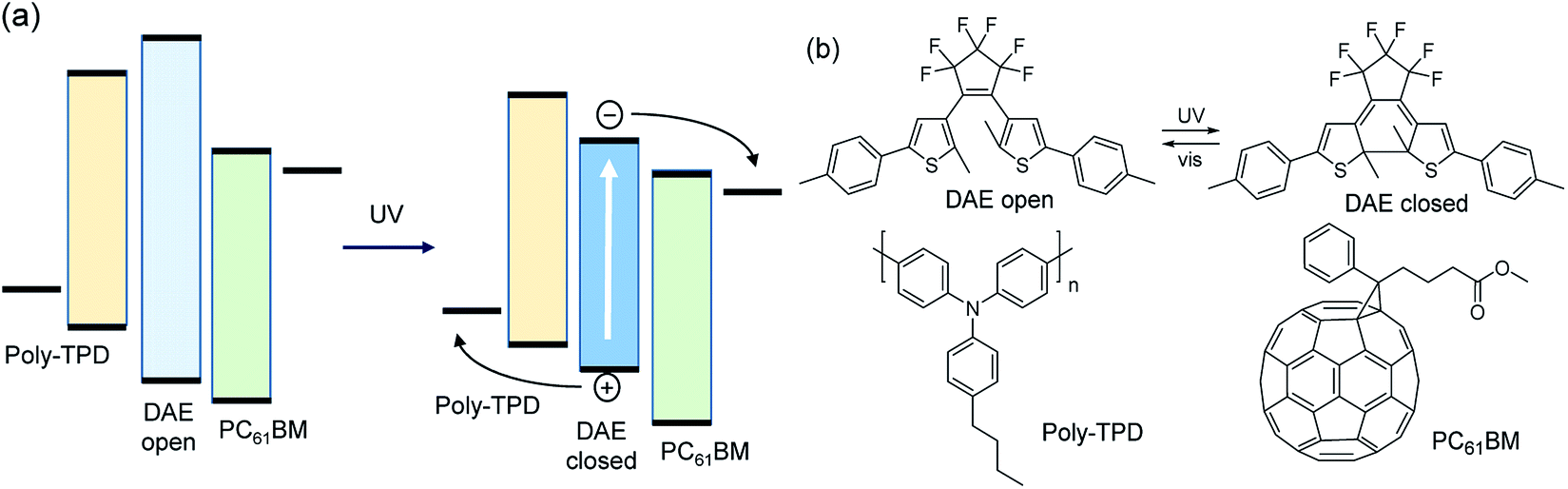 | ||
| Fig. 1 (a) Energy diagram of a photochromic organic solar cell. The photoactive layer is a ternary blend containing a photo-switchable dye (DAE) and organic donor and acceptor semiconductors for hole (poly-TPD) and electron transport (PC61BM). After switching the DAE dye with UV light from the colorless open-ring to the colored closed-ring isomer, absorption of visible light generates holes on the donor and electrons on the acceptor. (b) Structures of a DAE dye, poly-TPD, and PC61BM. | ||
For efficient charge generation, the energy levels of the highest occupied molecular orbital (HOMO) of the colored isomer of the photochromic dye should be positioned below the HOMO level of the donor, while the lowest unoccupied molecular orbital (LUMO) should be higher than that of the acceptor. In addition, the photochromic dye has to be spatially arranged to be simultaneously in electronic contact with the donor and acceptor materials. In this way, holes and electrons generated on the dye can be transported to the electrodes via the HOMO of the donor and LUMO of the acceptor. In this concept, the donor and acceptor govern the effective transport gap and thereby the open-circuit voltage. The short-circuit current is determined by the fraction of absorbed photons by the dye and the quantum efficiency by which excitons on the dye can generate charges that can be collected.
Irie's diarylethene (DAE) dyes are a versatile class of photochromic molecules.10 DAEs possess two thermally stable isomers (Fig. 1b) that can be interconverted selectively by illumination with UV or visible light. The colorless open-ring isomer and colored closed-ring isomer can retain switchability and fatigue resistance of the interconversion in the solid state and when dispersed in a polymer matrix.11–21 Hence, DAEs promise to be suitable candidates to construct photochromic devices. So far, DAE dyes have been used in functional electronic devices such as organic optical memories,11,21–27 organic electronic switches,12,26,28–34 transistors,12,35 and organic light-emitting diodes.36,37 In a bilayer structure with N,N′-di(1-naphthyl)-N,N′-diphenylbenzidine (NPB), DAEs generate a photocurrent.38
In this study three DAEs 1–3 were selected (Fig. 2). Their ring-open isomers (1a–3a) absorb light in the UV range at wavelengths λ < 350 nm, while the corresponding ring-closed isomers (1b–3b) absorb light across the entire visible part of the spectrum, i.e. at 450 nm < λ < 650 nm. For 1–3, the quantum yields both for the cyclization (φO–C) and cycloreversion (φC–O) reactions in various solvents and in solid matrices have been reported.11,39,40 DAEs 1a–3a exhibit high cyclization quantum yields (φO–C) of 0.40–0.65 in solution, but the cycloreversion quantum yields (φC–O) of the corresponding 1b–3b isomers are considerably lower: 0.01–0.02. This is a useful asset because a high φO–C/φC–O ratio is required to reach a significantly colored film in ambient sunlight which has relatively little intensity in the UV range compared to the visible range. The open-ring and closed-ring isomers of 1–3 have been reported to be thermally stable up to temperatures of 100 °C.11,39,40 This enables analyzing the properties of the uncolored and various photostationary states.
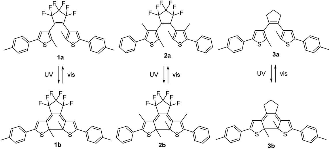 | ||
| Fig. 2 Structures of the open-ring (1a–3a) and closed-ring (1b–3b) DAE isomers. Selective illumination with UV or visible light results in their interconversion. | ||
The colorability of DAEs is less in thin film than in solution.23,41,42 This has been explained by considering that the open-ring isomer of DAE photochromes exists as a near 1![[thin space (1/6-em)]](https://www.rsc.org/images/entities/char_2009.gif) :1 mixture of two conformational isomers. One in which the aryl rings are oriented parallel to each other and one with these rings in an anti-parallel orientation (Fig. 3). Only the anti-parallel conformation can convert to the closed-ring isomer upon UV illumination.41,43–51 in accordance with a conrotatory mechanism for the photoinduced ring-closing.52–54 In solution, thermal interconversion between both the two conformers of the open-ring isomer proceeds rapidly at room temperature, but decreased orientational freedom in the solid state can restrict this interconversion.
:1 mixture of two conformational isomers. One in which the aryl rings are oriented parallel to each other and one with these rings in an anti-parallel orientation (Fig. 3). Only the anti-parallel conformation can convert to the closed-ring isomer upon UV illumination.41,43–51 in accordance with a conrotatory mechanism for the photoinduced ring-closing.52–54 In solution, thermal interconversion between both the two conformers of the open-ring isomer proceeds rapidly at room temperature, but decreased orientational freedom in the solid state can restrict this interconversion.
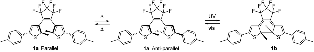 | ||
| Fig. 3 The parallel and antiparallel conformations of 1a that are interswitchable in solution but are less likely to interconvert in the solid phase. Correspondingly in the solid state the photochromic ring closure to 1b will occur from the antiparallel conformation of 1a. | ||
The aim of this work is to provide a proof-of-principle for a photochromic organic solar cell based on a ternary blend bulk heterojunction using DAE dyes. We will show that one of the three dyes selected (1), exhibits the desired functionality, giving a clear difference in photoresponse in the visible range after UV illumination converted the ring-open (1a) to the ring-closed (1b) isomer. The other two dyes do not exhibit this behavior, which is explained by either a poor photoconversion (2), or inappropriate positioning of the energy levels to act as a sensitizer (3).
2. Results and discussion
2.1 Optical and electrochemical properties
Table 1 lists the wavelength of maximum absorption (λmax), the onset of the optical absorption (λg), the optical band gap (Eg), the molar absorption coefficients (ε) and the quantum yields (φO–C and φC–O) inferred from measurements on solutions of the ring-open and ring-closed isomers of 1–3 before and after UV illumination in either hexane (1, 2) or acetonitrile (3).17,40,55 In all cases, the ring-open isomer is colorless and only absorbs light with wavelength λ < 400 nm.| Open-ring isomer | Closed-ring isomer | |||||||
|---|---|---|---|---|---|---|---|---|
| λmax (nm) | λg/Egb (nm eV−1) | ε (M−1 cm−1) | φO–C (at λmax) | λmax (nm) | λg/Egb (nm eV−1) | ε (M−1 cm−1) | φC–O (at 492 nm) | |
| a From ref. 17, 40 and 55.b Optical bandgaps were determined from the onset of the absorption. For 1 and 2 solutions in hexane;17,40 for 3 solution in acetonitrile.55 | ||||||||
| 1 | 285 | 330/3.76 | 3.99 × 10⁴ | 0.59 | 580 | 680/1.82 | 1.81 × 10⁴ | 0.013 |
| 2 | 262 | 310/4.00 | 2.80 × 10⁴ | 0.46 | 562 | 655/1.89 | 1.10 × 10⁴ | 0.015 |
| 3 | 279 | 340/3.65 | 3.45 × 10⁴ | 0.43 | 522 | 600/2.07 | 1.97 × 10⁴ | 0.01 |
For a working photochromic solar cell, the dyes must have appropriate energy levels for the HOMO LUMO compared to donor and acceptor materials used for charge transport to be able to generate free charges (Fig. 1a) upon illumination. In this study poly(4-butylphenyldiphenylamine) (poly-TPD) and [6,6]-phenyl C61 butyric acid methyl ester (PC61BM) are used as donor as acceptor, respectively. Poly-TPD has an optical band gap of about 2.9 eV and, hence, does not absorb in the visible spectral range. PC61BM has a much lower optical band gap of 1.75 eV, but the absorption coefficient is low in the visible range. Hence poly-TPD and PC61BM are suitable materials for a proof-of-concept. Cyclic voltammetry was used to determine the energy levels for 1–3,55–58 and to compare them to those of poly-TPD and PC61BM.
The open-ring isomers 1a–3a, all show irreversible oxidation waves (Fig. 4). For 3a, the onset of the oxidation is at lower potential than for 1a and 2a as result of the absence of the six electron withdrawing fluorine substituents on the cyclopentene ring. Compared to 1a, the onset of oxidation of 2a occurs at a slightly higher potential. A likely explanation is that the phenyl and thienyl rings cannot be coplanar in 2a because of steric hindrance by the methyl groups on the 3-position of the thienyl rings. The loss of coplanarity increases the oxidation potential. Interestingly, after oxidation of 1a and 3a, the signals in the subsequent reduction waves occur at potentials also found in the cyclic voltammograms of the ring-closed isomers 1b and 3b (Fig. 4a and c). This indicates that 1a and 3a undergo ring closure upon oxidation.59,60 For 2a this occurs to minor extent only. The reduction of the open-ring isomers 1a–3a occurs at potentials well below −2 V vs. Fc/Fc+. Only for 2a a reduction wave was observed (Fig. 4b), which is irreversible.
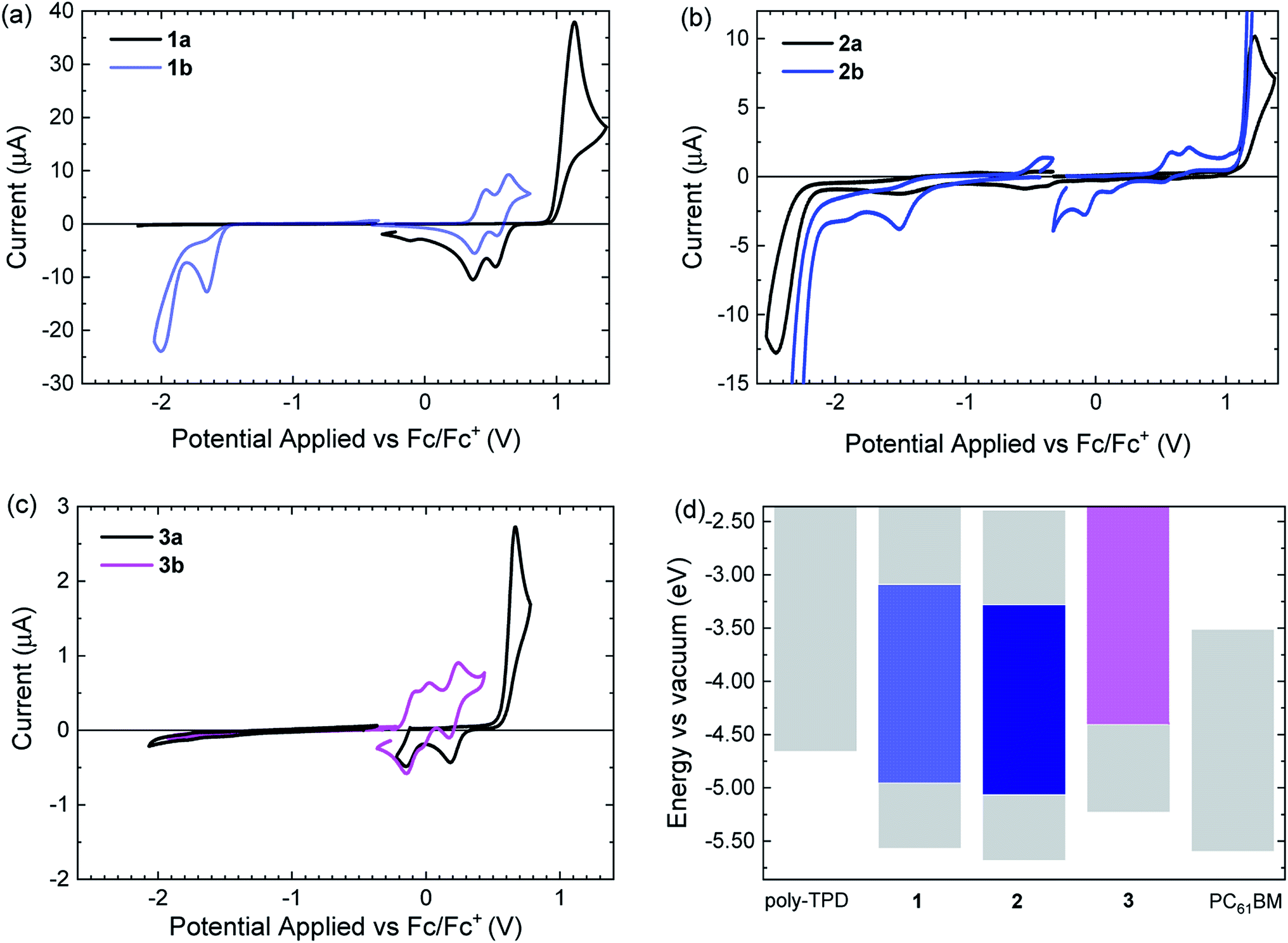 | ||
| Fig. 4 (a–c) Cyclic voltammograms of open-ring (black solid lines) and closed-ring isomers (colored solid lines) of 1–3 in acetonitrile. Potentials are versus Fc/Fc+. (d) Comparison of energy levels of 1–3 with those of poly-TPD and PC61BM. | ||
Of the closed-ring isomers, 1b and 3b show reversible oxidation waves. For 1b the oxidation involves two consecutive one-electron oxidations (Fig. 4a), while for 3b three closely spaced one-electron oxidation waves can be seen (Fig. 4c). The much lower oxidation potential of 3b compared to 1b is related to the electron-withdrawing fluorines on the cyclopentene ring in 3b. This also causes the occurrence of the third oxidation in 3b to the triple cation at relatively low potentials. The oxidation of 2b occurs at a higher potential than for 1b, because of steric hindrance by the methyl groups on the 3-position of the thienyl rings. In contrast to 1b and 3b, oxidation of 2b is irreversible, likely as a consequence of the absence of methyl groups on the para positions of the two phenyl rings. These methyl groups effectively hinder dimerization via carbon–carbon bond formation at the para positions after oxidation in 1b and 3b. After oxidation of 2b, the subsequent reduction wave shows signals at much lower potentials that probably result from the reduction of oxidized dimers of 2b that were coupled at the para positions. At negative potentials, 1b and 2b show an irreversible reduction wave. For 3b no reduction wave is observed and the reduction potential is probably low and outside the potential window of acetonitrile electrolyte used, as consequence of the lack of fluorine atoms. The onsets of the oxidation and reductions waves were used to estimate the energy levels of the HOMO and LUMO for the ring-open and ring-closed isomers of 1–3 and are collected in Table 2.
| EHOMO (eV) | ELUMO (eV) | ECVg (eV) | |
|---|---|---|---|
| a Conversion using E(Fc/Fc+) = −4.59 eV against vacuum.b No signal observed within the measured range. The LUMO energy must be >−2.3 eV.55–58 | |||
| Poly-TPD | −4.66 | >−2.3b | — |
| 1a | −5.57 | >−2.3b | — |
| 1b | −4.96 | −3.09 | 1.87 |
| 2a | −5.69 | −2.39 | 3.29 |
| 2b | −5.06 | −3.28 | 1.78 |
| 3a | −5.23 | >−2.3b | — |
| 3b | −4.41 | >−2.3b | — |
| PC61BM | −5.60 | −3.51 | 2.09 |
Based on the measured energy levels, some predictions for the performance in the solar cells can be made. Compounds 1b and 2b have HOMO and LUMO energies that lie between those of poly-TPD and PC61BM, but for 3b the HOMO energy is higher than that of poly-TPD. As consequence 3b will unlikely generate holes on poly-TPD after photoexcitation. For 1b and 2b the offsets (ΔEHOMO) of the HOMO energies with poly-TPD are 0.30 and 0.40 eV respectively, which is likely sufficient for charge transfer. The offsets (ΔELUMO) of the LUMO energies with PC61BM are 0.42 and 0.23 eV for 1b and 2b, respectively. A ΔELUMO of 0.23 eV for 2b is less than ∼0.3 eV that is often used as phenomenological threshold for charge transfer to occur.61
For several covalently linked DAE-C60 adducts it has been shown that the photochromism is quenched severely when compared to the non-covalently linked DAE equivalents in isolation.62 It was concluded that, due their close proximity, electron transfer from the DAE moiety to the fullerene cage is the cause of the decreased photochromism. To determine the photoswitchability of DAE dyes 1–3 in blends with poly-TPD and PC61BM, UV-vis absorption measurements were performed consecutively on DAE/poly-TPD/PC61BM blends in pristine films, after UV illumination, and after illumination with visible light (Fig. 5). In these experiments, the weight ratio between poly-TPD and PC61BM and was kept constant at 1:4. Fig. 5 shows the UV-vis spectra and photographs for films of the three dyes for a DAE to poly-TPD/PC61BM blend weight ratio of the of 2:1. The corresponding UV-vis spectra and photographs for DAE to poly-TPD/PC61BM blend weight ratios of 1:1 and 1:2 are shown in Fig. S1 and S2 ESI†.
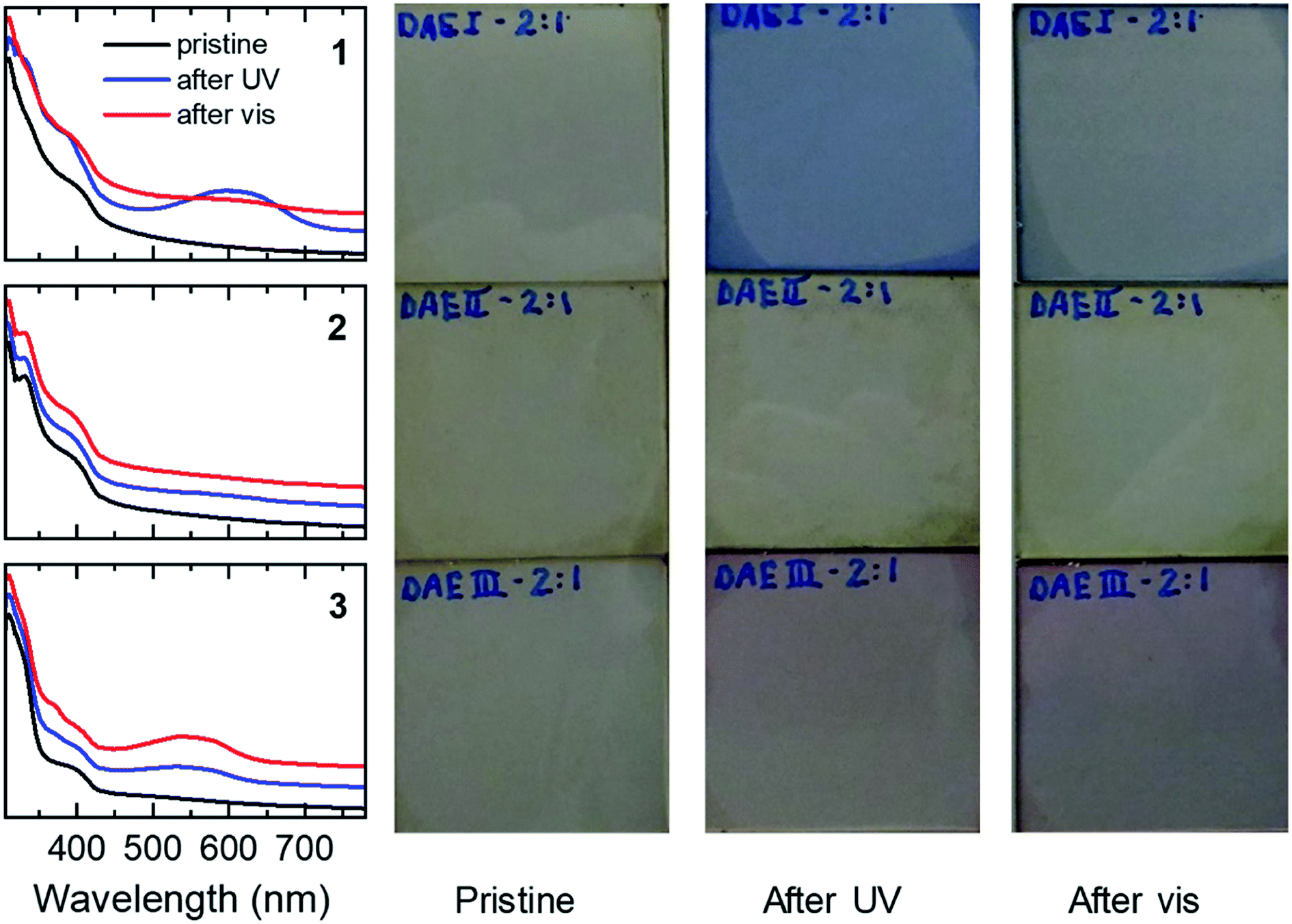 | ||
| Fig. 5 UV-vis absorption spectra and photographs of ternary blends of 1–3, PC61BM, and poly-TPD. The ratio DAE/poly-TPD/PC61BM weight ratio was 10:1:4. The samples were consecutively measured as pristine samples, after UV illumination, and after illumination with visible light as detailed in the Experimental section. The UV-vis spectra are offset vertically for clarity. | ||
The 1a/poly-TPD/PC61BM blends show an increased absorbance at 600 nm upon UV illumination, corresponding to the conversion of 1a to 1b. The conversion is reversible through illumination with white light from a tungsten halogen lamp. The cyclization and cycloreversion occur for each of the three blend compositions tested and the absorption at 600 nm is largest for the 2:1 blend. In contrast, the 2a/poly-TPD/PC61BM blend shows almost no photochromism. Even for the 2:1 weight ratio of 2a to poly-TPD/PC61BM, the change in absorption upon UV illumination is marginal. At present, we have no conclusive explanation for the different behavior of 1a and 2a. It might be that the methyl groups on 3-position of the thienyl rings in 2a cause too much steric hindrance in the solid state for the aromatic rings to become coplanar with the bridging cyclopentene ring. The 3a/poly-TPD/PC61BM blend showed a response to UV light in between that of 1a and 2a, generating a new band at ∼550 nm. Like for 1, the absorbance at 550 nm increases with the concentration of the dye in the blend. In contrast to 1, however, illumination with white light resulted in further coloration of the layers instead of the expected discoloration. Apparently, under these conditions, the UV light present in the white light has a higher efficiency for the cyclization of 3a that the visible light has for the cycloreversion of 3b. The photographs of the films corresponding confirm the color change to blue for 1 and to red for 3, but no change for 2, consistent with the changes in the UV-vis spectra. All films also show an additional brownish color, which is primarily due to the absorption of PC61BM. The surface topology of the blend films was checked before and after UV illumination using atomic force microscopy (AFM) (Fig. S3 ESI†). The blend films are very smooth with root-mean-square surface roughness (Rq) of 0.26 nm ≤ Rq ≤ 0.70 nm before and 0.28 nm ≤ Rq ≤ 0.37 nm after UV illumination.
2.2 Photochromic photovoltaic devices
Solar cells were made by sandwiching ternary blend films, consisting of the ring-open isomers 1a–3a, poly-TPD, and PC61BM between a transparent indium tin oxide (ITO) (180 nm)/poly(3,4-ethylenedioxythiophene):polystyrene sulfonate (PEDOT:PSS) (40 nm) front contact and an opaque LiF (1 nm)/Al (100 nm) back contact. The photovoltaic performance was first tested for pristine devices before any illumination induced changes to the system, and then after UV illumination (λ ≈ 365 nm) for 30 min. The assumption was made that the simulated AM1.5 G light used to evaluate the devices does not significantly affect the performance during the measurement. Fig. 6 shows the current density–voltage (J–V) characteristics and the corresponding external quantum efficiency (EQE) spectra for the three different blends. The photovoltaic parameters are summarized in Table 3. The results obtained for a device comprising a binary blend of poly-TPD and PC61BM are included in Table 1 as a reference and the performance is similar to previous reports.63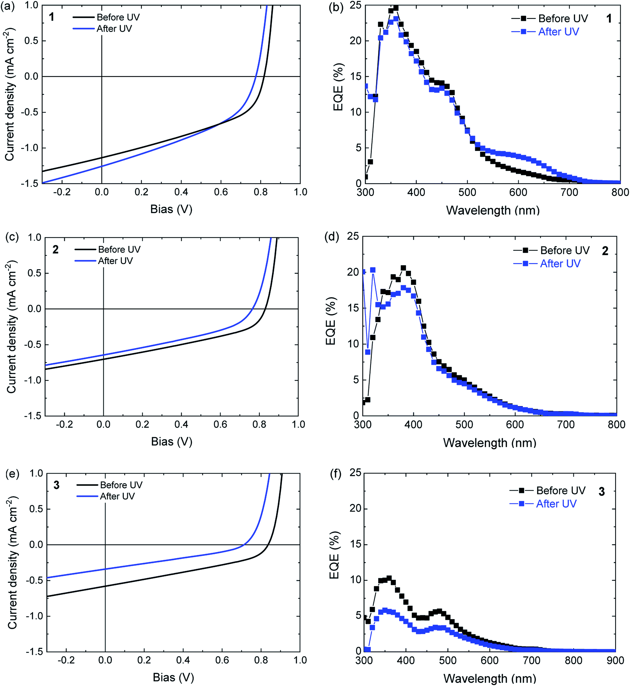 | ||
| Fig. 6 (a, c and e) Current density–voltage (J–V) characteristics of ternary DAE/poly-TPD/PC61BM solar cells before and after UV illumination to convert the ring-open isomer to the ring-closed isomer, measured under simulated AM1.5 G solar light. (b, d and f) Corresponding EQE spectra. (a and b) For DAE 1, (c and d) for DAE 2, (e and f) for DAE 3. | ||
| DAE | Ratio | d (nm) | UV | JSC (mA cm−2) | VOC (V) | FF | PCE (%) |
|---|---|---|---|---|---|---|---|
| a The average values and standard deviations were obtained over 13 devices. The poly-TPD/PC61BM reference cell data were measured on a single device. | |||||||
| 1 | 2:1:5 |
107 ± 2 | No | 1.13 ± 0.02 | 0.79 ± 0.06 | 0.40 ± 0.03 | 0.36 ± 0.05 |
| Yes | 1.18 ± 0.05 | 0.76 ± 0.02 | 0.39 ± 0.01 | 0.35 ± 0.03 | |||
| 2 | 3:1:5 |
109 ± 7 | No | 0.89 ± 0.06 | 0.79 ± 0.04 | 0.37 ± 0.01 | 0.27 ± 0.02 |
| Yes | 0.84 ± 0.06 | 0.75 ± 0.04 | 0.37 ± 0.01 | 0.24 ± 0.02 | |||
| 3 | 3:1:5 |
117 ± 13 | No | 0.64 ± 0.08 | 0.83 ± 0.03 | 0.33 ± 0.01 | 0.18 ± 0.02 |
| Yes | 0.47 ± 0.04 | 0.74 ± 0.02 | 0.31 ± 0.00 | 0.11 ± 0.01 | |||
| — | 0:1:5 |
160 | No | 1.79 | 0.77 | 0.43 | 0.59 |
| Yes | 1.77 | 0.76 | 0.43 | 0.58 | |||
When compared to the poly-TPD/PC61BM binary reference, the inclusion of either 1a, 2a, or 3a in the corresponding ternary blend results in a decrease in short-circuit current (JSC), a small increase in open-circuit voltage (VOC), and a decrease in fill factor (FF) to result in an overall lower power conversion efficiency (PCE) (Table 3). These results can be understood by considering that the open-ring isomers of the DAE dyes have an overlapping absorption with both poly-TPD and PC61BM and dilute the blend, which reduces charge generation as absorption by the open-ring isomers of the DAEs does not result in charge generation. The 10% increase in VOC possibly relates to the fact that 1a–3a have a significantly lower HOMO than poly-TPD in the binary blend system.64
UV illumination converts 1a to 1b and 3a to 3b, but does not ring close 2a to 2b in blends with poly-TPD/PC61BM (Fig. 5). For a solar cell based on a ternary blend of 1a with poly-TPD and PC61BM, UV illumination results in small increase in JSC from 1.13 ± 0.02 to 1.18 ± 0.05 mA cm−2 that mainly originates from photons absorbed around 600 nm as shown by the EQE spectrum in Fig. 6b. This spectral range corresponds to the absorption profile of 1b (Table 1 and Fig. 5) that is formed from 1a upon UV illumination. The small, but distinct contribution of 1b to the photocurrent in the EQE spectrum demonstrates that for DAE dye 1 charge generation occurs as shown in Fig. 1a, and that for excited 1b charge generation in the blend competes with the cycloreversion reaction. Whereas JSC has increased after UV illumination, the VOC decreases, and the FF remains virtually the same. The VOC (0.76 ± 0.02 V) is now similar to the VOC (0.76 V) of the cell with the binary poly-TPD/PC61BM blend.
As expected from the absence of a photochromic conversion from 2a to 2b in a blend with poly-TPD and PC61BM as inferred from Fig. 5, the J–V characteristics and EQE of a photovoltaic device consisting of a 2a/poly-TPD/PC61BM ternary blend are virtually identical before and after UV illumination (Fig. 6c and d). The only relevant change is a small decrease of VOC that is seen for all three DAE/poly-TPD/PC61BM cells.
For 3a, an overall decrease in photovoltaic performance is observed after UV illumination (Fig. 6e and f). The EQE spectrum shows a decrease in photocurrent generation over the entire spectrum. A plausible explanation is that the shallow HOMO energy of 3b impedes charge transport via poly-TPD by acting as a trap for the transport of holes. An alternative explanation for the reduced performance could be UV degradation of 3. The switching and photostability of analogs of 1 and 3 in solution has been studied by van Esch et al.65 They find that the perhydrocyclopentene is very stable towards photochemical decomposition, but roughly 2–3 times less than the corresponding perfluorocyclopentene. Because of the small difference and bearing in mind that 1 survives several cycles of 30 min. UV illumination, we consider it unlikely that 3 degrades significantly already in the first cycle. Also the red color and the corresponding change in the UV-vis spectrum after UV illumination (Fig. 5) show that 3 is largely converted to the closed form.
Fig. 5 shows that prolonged irradiation with visible light converts 1b back to 1a in blends with poly-TPD and PC61BM. This suggests that solar cells based on dye 1 can be switched between two states. Fig. 7 shows the effect of exposing 1/poly-TPD/PC61BM solar cells to alternating 30 min periods of UV and visible illumination and recording the J–V characteristics after each illumination period. The results show that JSC increases after each UV illumination and then decreases after subsequent exposure to visible light. The switching of JSC occurs over at least five consecutive cycles (total 5 hour illumination). Some oscillatory behavior can also be seen for the FF and VOC. Overall the parameters decrease with consecutive cycles. Fig. S4 (ESI†) shows the J–V characteristics of the pristine cell, and of the cell in the 1st and 5th cycle recorded in this experiment.
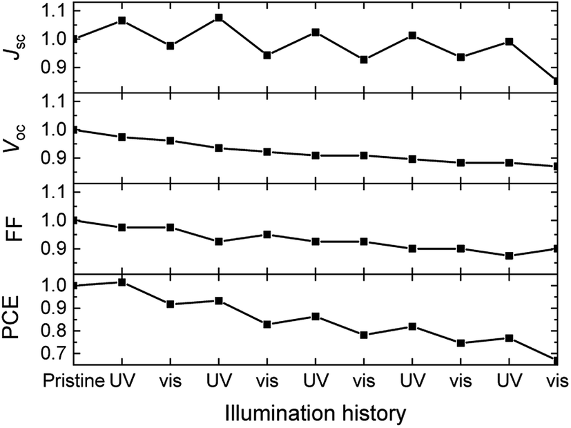 | ||
| Fig. 7 Evolution of the normalized photovoltaic parameters of solar cells based on 1/poly-TPD/PC61BM blends in five cycles of 30 min of UV illumination followed by 30 min exposure to visible light. | ||
3. Conclusions
DAE dyes 1–3 were evaluated to investigate the possibility of creating a photochromic organic solar cell. In combination with poly-TPD and PC61BM for hole and electron transport, DAE dye 1 afforded a photochromic layer that can be reversibly interconverted between a colorless ring-open (1a) and a colored ring-closed (1b) isomer. An organic solar cell based on a ternary blend of 1a/poly-TPD/PC61BM exhibited a distinct induced contribution at 600 nm in the EQE spectrum of the ring-closed isomer 1b after illuminating the cell with UV light. Hence, the ternary 1a/poly-TPD/PC61BM blend provides a proof-of-principle for a bulk heterojunction photochromic organic solar cell, exhibiting an increased EQE in the visible region of the solar spectrum after illumination with UV light to convert 1a to 1b. Despite the increased EQE, there is no increase in power conversion efficiency because of a concomitant reduction of open-circuit voltage and fill factor. The other two DAE dyes (2 and 3) did not yield photochromic organic solar cells. Dye 2 has a very limited photoswitchability from 2a to 2b in a blend with poly-TPD and PC61BM, such that UV illumination does not change the photovoltaic characteristics. For 3, the HOMO energy of the colored closed-ring isomer 3b is higher than that of poly-TPD which, such that it can act a trap for hole transport.While the 1a/poly-TPD/PC61BM shows the desired effect, the PCE of 0.35 ± 0.03% is very modest. There are some obvious reasons for the low overall PCE. First, the poly-TPD/PC61BM blend is not optimal for charge transport as evidenced by the low FF of the reference devices without DAE dyes. Second, the concentration of the 1 in the optimized blend is only 25% (by weight) and with an optimized layer thickness of 110 nm, not all light will be absorbed even if the conversion of 1a to 1b would be, and remain, quantitative. Third, for an optimal charge generation the DAE dyes should be solely positioned at the interface between poly-TPD and PC61BM. It is unlikely that this condition is met in the blends.
Future optimization of charge transport materials and photochromic dyes may alleviate some of the present limitations. In a later stage, after it has become clear how to increase the PCE of photochromic organic solar cells, the dyes can possibly be tuned to become thermally unstable in the closed-ring isomer. The future, perfect photochromic dye would be one that switches irreversibly to a colored form by using the UV part of sunlight and only relaxes via a thermal process to a colorless isomer in the absence of sunlight. In combination with transparent electrodes, this would enable creating a device that absorbs light and produces electrical energy in sunlight but returns to a colorless and transparent configuration in dim light and in the dark. Methods to tune the thermal stability of DAE dyes have been described in literature to such an extent that the thermal stability of both the both ring-open en ring-closed isomers can be selectively altered,23,66–70 even independently of the electronic properties of the DAE.68,71,72
4. Experimental section
DAE dyes 1 and 3 were provided by Michael Pätzel and Stefan Hecht of the Humboldt-Universität zu Berlin. DAE dye 2 was obtained from TCI and used as received. Poly-TPD with a molecular weight of 10–120 kg mol−1 was obtained from American Dye Source, Inc. PC61BM was purchased from Solenne BV. Processing solvents (SAF) were used as received.UV-vis spectroscopy was conducted on a PerkinElmer Lambda 1050 spectrophotometer equipped with a 3D WB PMT/InGaAs/PbS detector module. UV illumination of samples was performed with a benchtop UV light (TL 8W BLB 1FM/10X25CC, λ ≈ 365 nm, 30 min at a distance of ≈10 cm). Illumination with visible light was achieved with light from an unfiltered OSRAM 64610 HLX G6.35 50 W 12 V tungsten halogen lamp, for 30 min at a distance of ≈10 cm. Cyclic voltammetry was carried out using an Autolab PGSTAT 30 in inert atmosphere. The electrolyte consisted of 0.1 M tetrabutylammonium hexafluorophosphate (TBAPF6) in acetonitrile. A silver rod was used as counter electrode and a silver chloride coated silver rod (Ag/AgCl) as quasi-reference electrode. The measurements were performed at a scan speed of 0.1 V s−1 and potentials are quoted against the ferrocene/ferrocenium (Fc/Fc+) redox couple as external standard. For conversion to energy levels versus vacuum, E(Fc/Fc+) = −4.59 eV was used, based on a recent study.73 Values in the literature vary between −4.4 and −5.4 eV.74 Cyclic voltammetry (CV) was conducted both in the dark and under continuous illumination using a benchtop UV light (TL 8W BLB 1FM/10X25CC, λ ≈ 365 nm) as the light source. The assumption was made that the in situ generated concentration of ring-closed product would be sufficient for detection in CV.
Photovoltaic devices with an active area of 0.09 and 0.16 cm2 were fabricated by spin coating poly(ethylenedioxythiophene):poly(styrenesulfonate) (PEDOT:PSS) (Clevios P, VP Al4083) on pre-cleaned, patterned indium tin oxide (ITO) glass substrates (Naranjo Substrates). The photoactive layer was spin coated at 2000 rpm in air from a chlorobenzene solution at 100 °C always at a total concentration of 30 mg mL−1. For optimized devices, the weight ratios between DAE/poly-TPD/PC61BM were 2:1:5, 3:1:5 and 3:1:5, for 1, 2, and 3 respectively. For optimized poly-TPD/PC61BM reference devices, a range of ratios from 1:2 to 1:5 poly-TPD:PC61BM was tested. Ratios of 1:4 and 1:5 gave similar performance. The back electrode was deposited using high vacuum (≈5 × 10⁻⁷ mbar) thermal evaporation and consisted of a layer of LiF (1 nm) and Al (100 nm). Cells with active areas of 0.09 or 0.16 cm2 gave virtually identical results and showed no consistent trends in size-dependent differences.
J–V characteristics were measured using a Keithley 2400 source meter under ≈100 mW cm−2 white light illumination from a tungsten–halogen lamp filtered by a Hoya LB120 daylight filter. Short-circuit current densities and PCEs were calculated by integrating the AM1.5 G solar spectrum and the spectral response of the cells. EQEs were determined using modulated monochromatic light from a 50 W tungsten–halogen lamp (Philips Focusline) passing through a monochromator (Oriel Cornerstone 130) with the use of a mechanical beam chopper. The response was recorded as a voltage over a 50 Ω resistor (Stanford Research Systems SR570) using a lock-in amplifier (Stanford Research Systems SR830). A calibrated silicon cell with a known spectral response was used as a reference. During the measurement, the device was kept in a nitrogen-filled box behind a quartz window. UV illumination to switch the DAE dyes to the closed-ring isomers was afforded by a benchtop UV light (TL 8W BLB 1FM/10X25CC, λ ≈ 365 nm, 30 min at a distance of ≈10 cm).
The thicknesses of the active layers on the devices were determined using a Veeco Dektak 150 profilometer, subtracting the thicknesses of any underlying layers.
Conflicts of interest
There are no conflicts to declare.Acknowledgements
We thank Martin Herder, Stefan Hecht, and Michael Pätzel for providing dyes 1 and 3 and for stimulating discussions and Haijun Bin for recording the AFM data. We acknowledge funding from the European Research Council (Grant Agreement No. 339031) and the NWO Spinoza prize awarded to R. A. J. Janssen by the Netherlands Organization for Scientific Research (NWO), and the Ministry of Education, Culture and Science (Gravity program 024.001.035).References
- C. Cui and Y. Li, Energy Environ. Sci., 2019, 12, 3225–3246 RSC.
- O. Inganäs, Adv. Mater., 2018, 30, 1800388 CrossRef PubMed.
- V. Vohra, Chem. Rec., 2019, 19, 1166–1178 CrossRef CAS PubMed.
- W. Hou, Y. Xiao, G. Han and J. Y. Lin, Polymers, 2019, 11, 143 CrossRef PubMed.
- J. A. Luceño-Sánchez, A. M. Díez-Pascual and R. P. Capilla, Int. J. Mol. Sci., 2019, 20, 976 CrossRef PubMed.
- J. J. Wu, M. D. Hsieh, W. P. Liao, W. T. Wu and J. S. Chen, ACS Nano, 2009, 3, 2297–2303 CrossRef CAS PubMed.
- W. Wu, J. Wang, Z. Zheng, Y. Hu, J. Jin, Q. Zhang and J. Hua, Sci. Rep., 2015, 5, 8592 CrossRef CAS PubMed.
- S. Ma, H. Ting, Y. Ma, L. Zheng, M. Zhang, L. Xiao and Z. Chen, AIP Adv., 2015, 5, 057154 CrossRef.
- N. M. Johnson, Y. Y. Smolin, C. Shindler, D. Hagaman, M. Soroush, K. K. S. Lau and H. F. Ji, AIMS Mater. Sci., 2015, 2, 503–509 Search PubMed.
- M. Irie and M. Mohri, J. Org. Chem., 1988, 53, 803–808 CrossRef CAS.
- M. Irie, T. Lifka and K. Uchida, Mol. Cryst. Liq. Cryst., 1997, 297, 81–84 CrossRef CAS.
- E. Orgiu, N. Crivillers, M. Herder, L. Grubert, M. Pätzel, J. Frisch, E. Pavlica, D. T. Duong, G. Bratina, A. Salleo, N. Koch, S. Hecht and P. Samori, Nat. Chem., 2012, 4, 675–679 CrossRef CAS PubMed.
- M. Hamano and M. Irie, Jpn. J. Appl. Phys., 1996, 35, 1764–1767 CrossRef CAS.
- T. Leydecker, M. Herder, E. Pavlica, G. Bratina, S. Hecht, E. Orgiu and P. Samorì, Nat. Nanotechnol., 2016, 11, 769–775 CrossRef CAS PubMed.
- J. Frisch, M. Herder, P. Herrmann, G. Heimel, S. Hecht and N. Koch, Appl. Phys. A: Mater. Sci. Process., 2013, 113, 1–4 CrossRef CAS.
- Q. Wang, J. Frisch, M. Herder, S. Hecht and N. Koch, ChemPhysChem, 2017, 18, 722–727 CrossRef CAS PubMed.
- M. Irie, T. Lifka, S. Kobatake and N. Kato, J. Am. Chem. Soc., 2000, 122, 4871–4876 CrossRef CAS.
- R. Schmidt, M. Pärs, T. Weller, M. Thelakkat and J. Köhler, Appl. Phys. Lett., 2014, 104, 013304 CrossRef.
- C. Schörner, D. Wolf, T. Schumacher, P. Bauer, M. Thelakkat and M. Lippitz, J. Phys. Chem. C, 2017, 121, 16528–16532 CrossRef.
- T. Kato, K. Okano and T. Yamashita, J. Photopolym. Sci. Technol., 2010, 23, 241–244 CrossRef CAS.
- K. Shibata, K. Muto, S. Kobatake and M. Irie, J. Phys. Chem. A, 2002, 106, 209–214 CrossRef CAS.
- S. H. Kawai, S. L. Gilat, R. Ponsinet and J. M. Lehn, Chem.–Eur. J., 1995, 1, 285–293 CrossRef CAS.
- S. L. Gilat, S. H. Kawai and J. M. Lehn, Chem.–Eur. J., 1995, 1, 275–284 CrossRef CAS.
- M. Irie, Chem. Rev., 2000, 100, 1685–1716 CrossRef CAS PubMed.
- T. Tsujioka and H. Kondo, Appl. Phys. Lett., 2003, 83, 937–939 CrossRef CAS.
- M. Irie, T. Fukaminato, K. Matsuda and S. Kobatake, Chem. Rev., 2014, 114, 12174–12277 CrossRef CAS PubMed.
- M. Irie, T. Lifka, S. Kobatake and N. Kato, J. Am. Chem. Soc., 2000, 122, 4871–4876 CrossRef CAS.
- S. H. Kawai, S. L. Gilat and J. M. Lehn, Eur. J. Org. Chem., 1999, 2359–2366 CrossRef CAS.
- J. Areephong, W. R. Browne, N. Katsonis and B. L. Feringa, Chem. Commun., 2006, 3930–3932 RSC.
- H. Logtenberg, J. H. M. Van der Velde, P. De Mendoza, J. Areephong, J. Hjelm, B. L. Feringa and W. R. Browne, J. Phys. Chem. C, 2012, 116, 24136–24142 CrossRef CAS.
- T. Tsujioka and M. Irie, J. Photochem. Photobiol., C, 2010, 11, 1–14 CrossRef CAS.
- E. Orgiu and P. Samorì, Adv. Mater., 2014, 26, 1827–1845 CrossRef CAS PubMed.
- N. Zhang, W. Y. Lo, A. Jose, Z. Cai, L. Li and L. Yu, Adv. Mater., 2017, 33, 1701248 CrossRef PubMed.
- Z. Liu, H. I. Wang, A. Narita, Q. Chen, Z. Mics, D. Turchinovich, M. Kläui, M. Bonn and K. Müllen, J. Am. Chem. Soc., 2017, 139, 9443–9446 CrossRef CAS PubMed.
- M. El Gemayel, K. Börjesson, M. Herder, D. T. Duong, J. A. Hutchison, C. Ruzié, G. Schweicher, A. Salleo, Y. Geerts, S. Hecht, E. Orgiu and P. Samori, Nat. Commun., 2015, 6, 6330 CrossRef CAS PubMed.
- Z. Zhang, X. Liu, Z. Li, Z. Chen, F. Zhao, F. Zhang and C. H. Tung, Adv. Funct. Mater., 2008, 18, 302–307 CrossRef CAS.
- P. Zacharias, M. C. Gather, A. Köhnen, N. Rehmann and K. Meerholz, Angew. Chem., Int. Ed., 2009, 48, 4038–4041 CrossRef CAS PubMed.
- T. Tsujioka, M. Yamamoto, K. Shoji and K. Tani, Photochem. Photobiol. Sci., 2010, 9, 157–161 RSC.
- S. Fredrich, R. Göstl, M. Herder, L. Grubert and S. Hecht, Angew. Chem., Int. Ed., 2016, 55, 1208–1212 CrossRef CAS PubMed.
- M. Irie, K. Sakemura, M. Okinaka and K. Uchida, J. Org. Chem., 1995, 60, 8305–8309 CrossRef CAS.
- T. Kawai, N. Fukuda, D. Gröschl, S. Kobatake and M. Irie, Jpn. J. Appl. Phys., 1999, 38, L1194–L1196 CrossRef CAS.
- M. Irie, O. Miyatake, K. Uchida and T. Eriguchi, J. Am. Chem. Soc., 1994, 116, 9894–9900 CrossRef CAS.
- S. Fukumoto, T. Nakashima and T. Kawai, Angew. Chem., Int. Ed., 2011, 50, 1565–1568 CrossRef CAS PubMed.
- T. Yamaguchi and M. Irie, J. Photochem. Photobiol., A, 2006, 178, 162–169 CrossRef CAS.
- A. Goldberg, A. Murakami, K. Kanda, T. Kobayashi, S. Nakamura, K. Uchida, H. Sekiya, T. Fukaminato, T. Kawai, S. Kobatake and M. Irie, J. Phys. Chem. A, 2003, 107, 4982–4988 CrossRef CAS.
- M. Boggio-pasqua, M. Ravaglia, M. J. Bearpark, M. Garavelli and M. A. Robb, J. Phys. Chem. A, 2003, 107, 11139–11152 CrossRef CAS.
- S. Kobatake, K. Uchida, E. Tsuchida and M. Irie, Chem. Commun., 2002, 2804–2805 RSC.
- S. Nakamura, T. Kobayashi, A. Takata, K. Uchida, Y. Asano, A. Murakami, A. Goldberg, D. Guillaumont, S. Yokojima, S. Kobatake and M. Irie, J. Phys. Org. Chem., 2007, 20, 821–829 CrossRef CAS.
- D. Guillaumont, T. Kobayashi, K. Kanda, H. Miyasaka, K. Uchida, S. Kobatake, K. Shibata, S. Nakamura and M. Irie, J. Phys. Chem. A, 2002, 106, 7222–7227 CrossRef CAS.
- K. Uchida, D. Guillaumont, E. Tsuchida, G. Mochizuki, M. Irie, A. Murakami and S. Nakamura, J. Mol. Struct., 2002, 579, 115–120 CrossRef CAS.
- Y. Asano, A. Murakami, T. Kobayashi, A. Goldberg, D. Guillaumont, S. Yabushita, M. Irie and S. Nakamura, J. Am. Chem. Soc., 2004, 126, 12112–12120 CrossRef CAS PubMed.
- J. Clayden, N. Greeves, S. Warren and P. Wothers, Organic Chemistry, Oxford University Press, 2009 Search PubMed.
- J. E. McMurry, Organic Chemistry, Thomson, 2008 Search PubMed.
- R. B. Woodward and R. Hoffmann, J. Am. Chem. Soc., 1965, 87, 395–397 CrossRef CAS.
- M. Herder, B. M. Schmidt, L. Grubert, M. Pätzel, J. Schwarz and S. Hecht, J. Am. Chem. Soc., 2015, 137, 2738–2747 CrossRef CAS PubMed.
- M. Herder, F. Eisenreich, A. Bonasera, A. Grafl, L. Grubert, M. Pätzel, J. Schwarz and S. Hecht, Chem.–Eur. J., 2017, 23, 3743–3754 CrossRef CAS PubMed.
- M. Herder, Improving the Design of Diarylethene Photoswitches and their Exploitation as Remote-Controlled Building Blocks, PhD Thesis, Humboldt-Universität Berlin, 2015.
- M. Yoshida, K. Suemori, S. Uemura, S. Hoshino, N. Takada, T. Kodzasa and T. Kamata, Jpn. J. Appl. Phys., 2010, 49, 04DK09 Search PubMed.
- W. R. Browne, J. J. D. De Jong, T. Kudernac, M. Walko, L. N. Lucas, K. Uchida, J. H. Van Esch and B. L. Feringa, Chem.–Eur. J., 2005, 11, 6414–6429 CrossRef CAS PubMed.
- W. R. Browne, J. J. D. De Jong, T. Kudernac, M. Walko, L. N. Lucas, K. Uchida, J. H. Van Esch and B. L. Feringa, Chem.–Eur. J., 2005, 11, 6430–6441 CrossRef CAS PubMed.
- M. C. Scharber, D. Mühlbacher, M. Koppe, P. Denk, C. Waldauf, A. J. Heeger and C. J. Brabec, Adv. Mater., 2006, 18, 789–794 CrossRef CAS.
- A. R. Tuktarov, A. A. Khuzin, A. R. Akhmetov, V. A. Barachevsky, O. V. Venidiktova and U. M. Dzhemilev, Tetrahedron Lett., 2015, 56, 7154–7157 CrossRef CAS.
- L. Blankenburg, L. S. Sensfuss, H. Schache, J. Marten, R. Milker and M. Schrödner, Synth. Met., 2015, 199, 93–104 CrossRef CAS.
- Q. An, F. Zhang, J. Zhang, W. Tang, Z. Deng and B. Hu, Energy Environ. Sci., 2016, 9, 281–322 RSC.
- J. J. D. de Jong, L. N. Lucas, R. Hania, A. Pugzlys, R. M. Kellogg, B. L. Feringa, K. Duppen and J. H. van Esch, Eur. J. Org. Chem., 2003, 1887–1893 CrossRef CAS.
- S. Nakamura and M. Irie, J. Org. Chem., 1988, 53, 6136–6138 CrossRef CAS.
- S. Takami, S. Kobatake, T. Kawai and M. Irie, Chem. Lett., 2003, 32, 892–893 CrossRef CAS.
- S. Kawai, T. Nakashima, K. Atsumi, T. Sakai, M. Harigai, Y. Imamoto, H. Kamikubo, M. Kataoka and T. Kawai, Chem. Mater., 2007, 19, 3479–3483 CrossRef CAS.
- D. Chen, Z. Wang and H. Zhang, J. Mol. Struct.: THEOCHEM, 2008, 859, 11–17 CrossRef CAS.
- S. Nakamura, S. Yokojima, K. Uchida, T. Tsujioka, A. Goldberg, A. Murakami, K. Shinoda, M. Mikami, T. Kobayashi, S. Kobatake, K. Matsuda and M. Irie, J. Photochem. Photobiol., A, 2008, 200, 10–18 CrossRef CAS.
- S. Kobatake, K. Uchida, E. Tsuchida and M. Irie, Chem. Lett., 2000, 29, 1340–1341 CrossRef.
- S. Kobatake and M. Irie, Chem. Lett., 2003, 32, 1078–1079 CrossRef CAS.
- R. E. M. Willems, C. H. L. Weijtens, X. de Vries, R. Coehoorn and R. A. J. Janssen, Adv. Energy Mater., 2019, 9, 1803677 CrossRef.
- C. M. Cardona, W. Li, A. E. Kaifer, D. Stockdale and G. C. Bazan, Adv. Mater., 2011, 23, 2367 CrossRef CAS PubMed.
Footnote |
| † Electronic supplementary information (ESI) available. See DOI: 10.1039/d0ra04508j |
| This journal is © The Royal Society of Chemistry 2020 |