
 Open Access Article
 This Open Access Article is licensed under a Creative Commons Attribution-Non Commercial 3.0 Unported Licence
Corrosion behaviour of 7075 aluminium alloy in acidic solution
Przemysław Kwolek *
*
Rzeszow University of Technology, Faculty of Mechanical Engineering and Aeronautics, Department of Materials Science, Poland. E-mail: pkwolek@prz.edu.pl
First published on 10th July 2020
Abstract
The objective of this work was to establish the influence of sodium molybdate on the corrosion kinetics of 7075 aluminium alloy in orthophosphoric acid aqueous solution. Corrosion rate was decreased from 75.98 to 3.24 g per m2 per day. The mechanism of corrosion inhibition was studied using scanning electron microscopy, X-ray photoelectron spectroscopy, UV-Vis spectrophotometry and electrochemical impedance spectroscopy. It was revealed that heteropolyoxomolybdate species act as the corrosion inhibitor. They adsorb onto the surface and inhibit an anodic process. Their influence on a cathodic process is much weaker. Phosphomolybdenum blue species do not inhibit corrosion process and their formation is undesirable.
1. Introduction
Aluminium alloys are widely used as a structural material due to their high strength-to-volume ratio, which is the result of the alloying process and subsequent heat treatment. 7075 alloy, belonging to the group of aluminium alloys with the highest mechanical properties, is one of the best examples. Usually, it is used in aerospace, mechanics, sport and leisure equipment. Unfortunately, its wear resistance is often insufficient for engineering applications and protective coatings are necessary.1,2Wear resistant coatings onto 7075 alloy are produced in two surface finishing processes: hard anodising and plasma electrolytic oxidation.3,4 Technology of these processes often requires etching in acidic solutions. This includes evaluation of the quality of hard anodic coating, i.e. destructive determination of its weight, as well as coating's removal when necessary, and is performed in H3PO4 solutions. In these cases, metallic substrate must not undergo dissolution and efficient corrosion inhibitor is necessary. Up to now, the most common, cheap and effective inhibitor is CrO3.5 Unfortunately, chromium(VI) species are highly toxic.6 So far, the most tested corrosion inhibitors in acidic solutions were organic compounds including amines, nitrogen heterocycles, different kinds of polymers, organic dyes, Schiff bases and plant extracts.7–12 Inorganic compounds were less popular. The most important here are molybdates.13–17
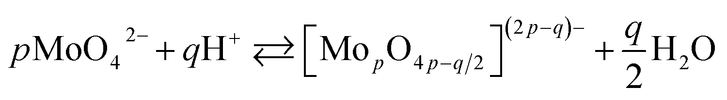
The chemistry of molybdenum in its highest oxidation state in aqueous solutions is complex. When adding a mineral acid to aqueous solution of orthomolybdate, addition and condensation processes occur and isopolyoxomolybdate is formed according to the eqn (1):
 | (1) |
When one or more additional elements are present in the solution during addition and condensation of orthomolybdate, heteropolyoxomolybdate is formed. About 60 elements on the periodic table, including phosphorus, can act as heteroatoms. The most well-known heteropolyoxomolybdate is [PMo12O40]3−. It can be easily reduced to phosphomolybdenum blue [PMo12O40]7−, where Mo exists both in V and VI oxidation state. This process is used for spectrophotometric determination of phosphorus concentration in the solution. The reduction reaction is complex and involves 2, 4 or even 6 electrons, depending on the applied reductant, pH, concentrations and proportion of the reagents.22
Aluminium, when immersed in H3PO4 solution containing heteropolyoxomolybdate, act as an electron donor and phosphomolybdenum blue species are formed on its surface. It was initially assumed that their adsorption inhibits the corrosion of 1050 alloy.13 Anodic coatings, produced onto 1050 alloy, were successfully stripped using Na2MoO4 instead of CrO3 and the coating weight was determined.15 This was a very promising result, some issues however emerged. First, at certain Na2MoO4 concentration range an insoluble salt precipitated on the aluminium. This complicates gravimetric determination of the anodic coatings' weight because appropriate concentration range of Na2MoO4 should be found.15 Second, an inhibition efficiency for some alloys such as 2024 seems to be insufficient for such an application.16 Third, sodium molybdate decreases the dissolution rate of anodic coatings.23 It is not known, however, whether chromate species behave in the same manner. Nevertheless, sodium molybdate still remains interesting candidate for chromium trioxide replacement.
In this work, the influence of sodium molybdate initial concentration on corrosion rate of 7075 alloy was studied. This is important from the practical point of view, because this alloy is often hard anodized and gravimetric determination of coating's weight is mandatory for such a process. What is more, the results of electrochemical and spectrophotometric studies revealed the mechanism of corrosion inhibition in the studied system and the role of phosphomolybdenum blue species.
2. Experimental
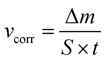
Aluminium rod, 10 mm diameter, made of 7075 aluminium alloy in the T6 state (heat treated and artificially aged) was obtained from Adamet-Niemet Poland (Table 1). Specimens, 2 mm thick, with a hole, 1.5 mm diameter, were prepared. They were ground with SiC papers (320 and 500 grit), rinsed with water, isopropyl alcohol, air-dried and weighted. The test solutions were prepared by dissolving appropriate amounts of Na2MoO4·2H2O in 0.5 M H3PO4 to obtain concentrations cMo = 0, 10, 50 and 100 mM. Their pH was adjusted using concentrated H2SO4 at 1.05. The specimens were hanged in test solutions, 250 cm3 per one specimen, using a nylon thread. The solutions were open to air. Their temperature, T = 303 K, was controlled using a water bath. After t = 600 min the specimens were rinsed with water, isopropyl alcohol, air-dried and weighted. Corrosion rates were calculated independently for three specimens, using eqn (2) and then averaged:
 | (2) |
 | (3) |
| Concentration of elements, wt% | |||||
|---|---|---|---|---|---|
| Al | Zn | Mg | Cu | Si | Fe |
| 91.31 | 4.21 | 3.11 | 1.29 | 0.06 | 0.02 |
One specimen of the each set was then etched in 0.5 M H3PO4 + 0.1 M Cr2O72− solution, T = 363 K, to remove any insoluble corrosion product from the surface, and the corrosion rate was again calculated.
Microscopic examination of the surface of the alloy prior corrosion test and corroded specimens was performed using Phenom XL scanning electron microscope (Thermo Fisher Scientific Inc., Waltham, U.S.) equipped with an energy-dispersive X-ray spectrometer (EDS). Accelerating voltage was 15 kV and the spot size ca. 8 nm.
Additional characterisation of the corrosion products obtained when cMo = 100 mM was performed using PHI 5000 Versa Probe II X-ray photoelectron spectrometer (ULVAC-PHI, Chigasaki, Japan). Al Kα X-ray beam, 100 μm, 25 W was applied. The photoelectron spectra were acquired from 300 × 300 μm areas, the analyser pass energy was 46.95 eV. The operating pressure in the chamber was <5 × 10⁻⁷ Pa, the charging effect was compensated using a dual-beam charge neutraliser. One area of the sample, 3 × 3 mm2, was pre-sputtered with an argon gas cluster ion beam to remove a potential contamination form the surface. The beam energy was 10 keV, beam current 30 nA and sputtering time 5 minutes. The carbon C 1s peak with binding energy of 284.8 eV was used as a reference for all XPS peaks. Spectrum background was subtracted using the Shirley method. PHI MultiPak™ data analysis software was used to calculate elemental compositions from the peak areas.
UV-Vis absorption spectra of the solutions before and after corrosion tests were measured in the quartz cuvettes, with 10 mm optical path length, using Cary 60 spectrophotometer (Agilent Technologies Inc., Santa Clara, US).
Working electrodes for electrochemical characterisation of the corrosion mechanism were prepared according to the following procedure. An electrical contact, made of aluminium alloy wire, was attached to the base of a 10 mm long cylindrical specimen. The wire was insulated from the solution using a heat shrink tube, the specimen and the electrical connection was then mounted in an epoxy resin. The surface area of the electrode, exposed to the solution was 0.785 cm2. Prior every experiment it was ground with SiC abrasive paper (320 and 500 grit), rinsed with water, isopropyl alcohol, and air-dried. Electrochemical analysis were performed using SP-300 potentiostat (Bio-Logic SAS, Seyssinet-Pariset, France). Working electrode was immersed in 100 cm3 test solutions, 20 cm2 platinum counter electrode and Ag|AgCl (3 M KCl) reference electrode were applied. The latter was placed in a Luggin probe filled with 0.5 M H3PO4 solution. Test solutions contained 0.5 M H3PO4 and 0, 10, 50, 100 mM of Na2MoO4, pH = 1.05. To ensure constant temperature of the solutions T = 303 K, electrochemical tests were performed in a cell with a water jacket; the cell was open to air. All the experiments were performed in a Faraday cage.
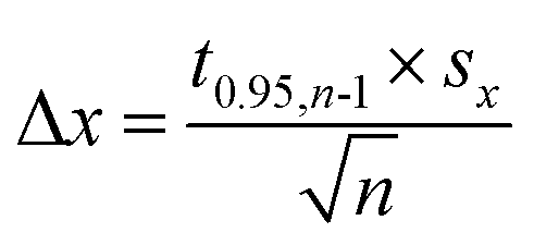
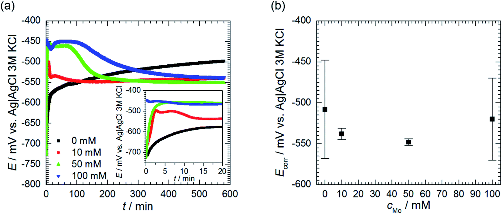
Open circuit potential (OCP) of 7075 aluminium alloy was recorded for t = 580 min prior further electrochemical characterisation of the system. OCP values, averaged over the last 40 min of immersion, were regarded as a corrosion potential Ecorr. This was studied as a function of cMo. Values averaged over three, cMo = 0 mM, four cMo = 10 and 50 mM or six, cMo = 100 mM independent measurements are presented.
The main analytical method applied was electrochemical impedance spectroscopy (EIS). The impedance spectra were measured after t = 580 min immersion of the specimens, when the OCP was sufficiently stable, in the frequency domain between 200 kHz and 10 mHz. A sinusoidal perturbation of potential equal to 5 mV of a root mean square was applied. First, the EIS spectrum was measured for cMo = 0 mM, at OCP, in a stagnant solution. Then, the same solution was agitated using magnetic stirrer for 60 min, with agitation speed 250 rpm, and the spectrum was measured. Second, the EIS spectra were recorded for cMo = 100 mM, at OCP, in the stagnant solutions. Then, the working electrode was polarised, either 100 mV anodically, or 100 mV cathodically vs. OCP. Time necessary for achieving the stationary state was 60 and 164 min respectively. Then, the EIS spectra were again measured. Third, the influence of sodium molybdate initial concentration, cMo = 0, 10, 50 and 100 mM on the EIS spectra was studied at OCP, in stagnant solutions. The number of independent experiments was n = 3 for cMo = 0 mM, n = 4 for cMo = 10 and 50 mM and n = 6 for cMo = 100 mM. All the spectra were validated using a Kramers–Kronig transformation with a KK Test software, version 1.01.25,26 Then, they were fitted with the appropriate electrical equivalent circuit (EEC) in a Zview software (Scribner Associates, version 3.5d). The weighted sum of squares of differences between measured and calculated impedances S were used to estimate the quality of the fit.
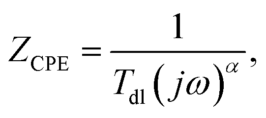
Corroding metal/solution interphase is modelled in EIS using resistance of the electrolyte Rs and a double layer capacitance of the electrode Cdl connected in parallel to a faradaic impedance. The latter takes into account various possible processes such as charge transfer, diffusion or adsorption. In real systems, time constants of the faradaic processes are distributed onto electrode. Thus, a constant phase element CPE is commonly used for modelling instead of the capacitor. The impedance of CPE is given by eqn (4):27
 | (4) |
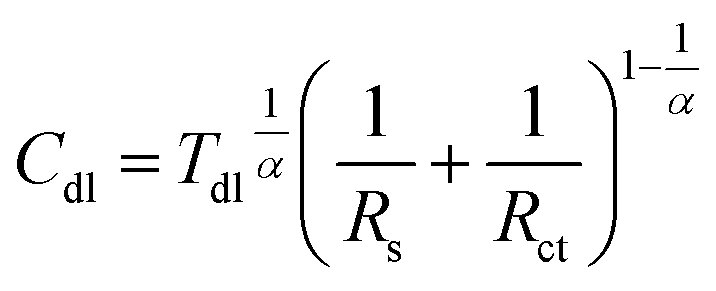 | (5) |
DC electrochemical methods were also applied to study the corrosion mechanism. Cyclic voltammograms of 0.5 M H3PO4 solutions containing cMo = 0 and 100 mM were recorded using a glassy carbon working electrode at a scan rate 20 mV s−1, T = 303 K. Polarisation curves of 7075 aluminium alloy were obtained as a function of cMo in stagnant solutions, T = 303 K. Cathodic and anodic branches of the curves were measured independently, starting from the OCP, with the scan rate 15 mV min−1.
3. Results and discussion
3.1. Gravimetric and spectroscopic analysis
Corrosion rate of 7075 aluminium alloy, estimated using a gravimetric method, decreases as sodium molybdate initial concentration cMo increases (Fig. 1). When cMo = 10 and 100 mM, an insoluble salt precipitated on the surfaces of the specimens. This occurred to much lesser extent when cMo = 50 mM. This salt was mostly dissolved in 0.5 M H3PO4 + 0.1 M Cr2O72− hot (363 K) solution for one set of specimens. It can be concluded that the precipitation affected weight losses of the specimens only slightly. The lowest corrosion rate, 3.24 g per m2 per day, was obtained for cMo = 100 mM. It corresponds to inhibition efficiency ca. 96%.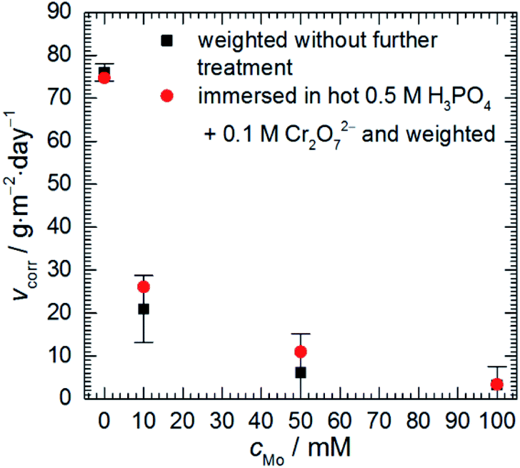 | ||
| Fig. 1 Corrosion rate of 7075 aluminium alloy as a function of sodium molybdate initial concentration; 0.5 M H3PO4, T = 303 K, t = 600 min. | ||
These results can be compared with those obtained for other aluminium alloys. Corrosion rate of 2024 alloy at T = 303 K, cMo = 25 mM was 2.74 g per m2 per day.16 In the case of 1050 alloy 2.80 g per m2 per day was obtained at T = 303 K, cMo = 10 mM.17
Corrosion experiments were performed in aerated, acidic solutions. Thus, three cathodic processes are possible: reduction of H3O+ to H2, O2 to H2O and heteropolyoxomolybdate to phosphomolybdenum blue. The latter process was qualitatively studied using UV-Vis spectroscopy. Heteropolyoxomolybdates strongly absorb light in the ultraviolet range, therefore, analysed solutions had to be diluted 200 times. Sulphuric(VI) acid, pH = 1.05, was applied as a diluting agent to ensure the same pH and Mo/P ratio as in the corrosion experiments.
First of all, the absorption spectra of the solutions with different initial concentration of heteropolyoxomolybdates were recorded, prior corrosion experiments. The shape of the spectra does not depend on cMo, only intensities do. The spectra are composed of two overlapping absorption bands in the UV range with clearly visible maxima at 216 nm (Fig. 2a). This is Mo–O ligand-to-metal charge transfer band.22 The UV range of the spectra did not change after the corrosion experiments. Weak absorption appeared, however, at λ > 500 nm (Fig. 2b). When cMo = 10 mM, two absorption bands are observed: at 688 and 822 nm. When cMo > 10 mM the former becomes stronger and the latter diminishes. These are Mo(V)–Mo(VI) intervalent charge transfer bands. Intensity of the former, λmax between 600 and 700 nm, is of moderate intensity, with absorption coefficient ε ≈ 10![[thin space (1/6-em)]](https://www.rsc.org/images/entities/char_2009.gif) 000 dm3 mol−1 cm−1. The latter, 700 < λmax < 800 nm, is stronger, ε ≈ 26000–34000 dm3 mol−1 cm−1.
000 dm3 mol−1 cm−1. The latter, 700 < λmax < 800 nm, is stronger, ε ≈ 26000–34000 dm3 mol−1 cm−1.
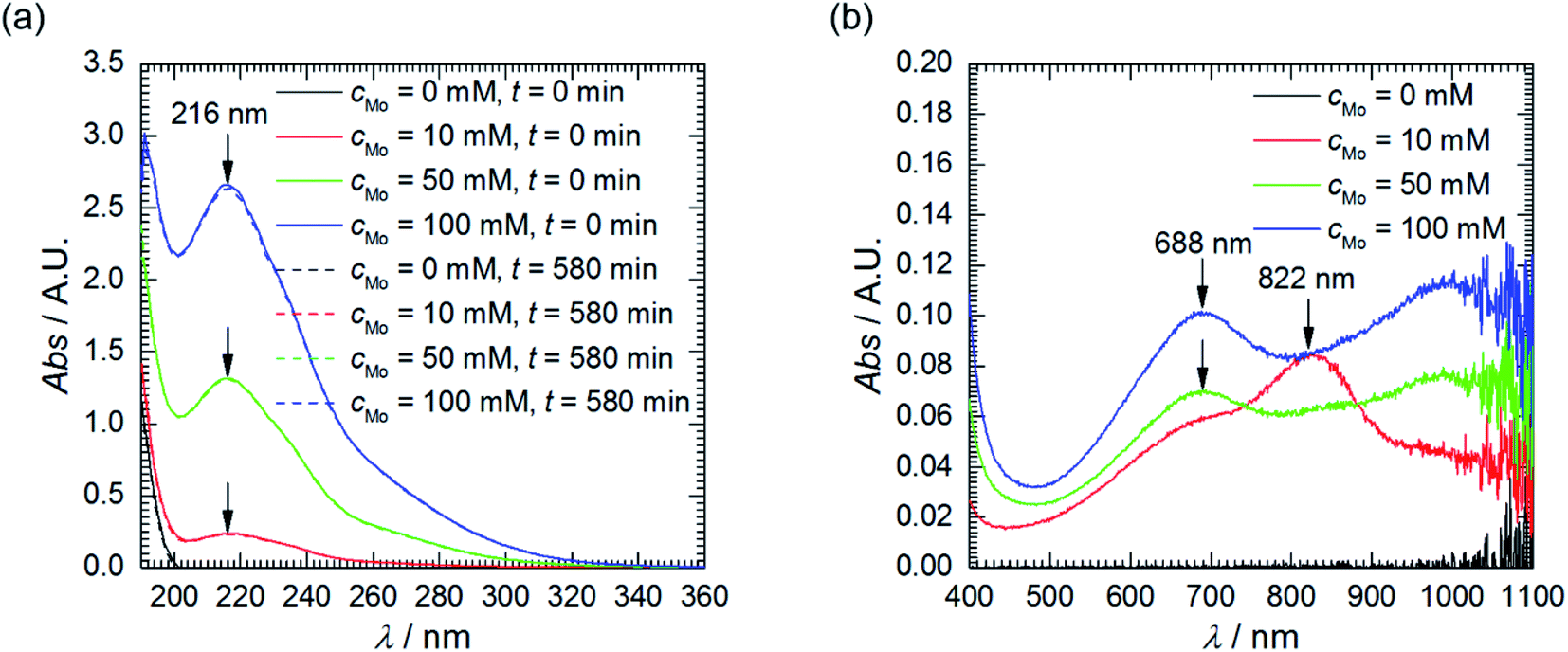 | ||
| Fig. 2 UV-Vis absorption spectra of solutions as a function of cMo: (a) prior and after corrosion tests, diluted 200-fold using H2SO4, pH = 1.05; (b) after corrosion tests, undiluted. | ||
These absorption bands are used in analytical chemistry for determination of phosphorus concentration in aqueous solutions. Unfortunately, their positions and intensities strongly depend on the concentrations of reagents and proportions between them.22 This explains the difference between cMo = 10 mM and cMo > 10 mM and, at the same time, makes impossible exact determination of concentration of phosphomolybdenum blue. Nevertheless, it can be roughly estimated. It is very low, ca. 10−5 to 10−6 mol dm−3 and increases as cMo increases. This explains why the absorption band at 216 nm virtually did not decrease after the corrosion experiments and brings up the question of whether phosphomolybdenum blue can act as the corrosion inhibitor in the studied system. It could be useful to check whether its concentration is sufficiently high to cover the surface of the electrode and ensure the corrosion inhibition. The average diameter of phosphomolybdenum blue formed in these experiments remains unknown, but, for the estimation, H3[PW12O40] Keggin structure, with average diameter of 0.8 nm, was assumed.28 Rough calculation indicated, that such a low concentration is sufficient to ensure the complete coverage of the electrode. In addition, oxygen dissolved in the solution can decrease the concentration of phosphomolybdenum blue.22 Thus, UV-Vis spectroscopy cannot answer the aforementioned question unambiguously. This was done based on the results of electrochemical investigation.
3.2. Microscopic analysis
Major alloying elements and impurities of 7075 alloy are Zn, Mg, Cu, Si and Fe. They form several intermetallics determining mechanical properties and corrosion resistance of the alloy. EDS maps of the specimens prior corrosion experiments indicated that vast majority of the intermetallics were composed of Al, Cu and Fe, with different Cu/Fe ratios and Al contents. The brighter ones (Fig. 3a) are probably Al7Cu2Fe. EDS point analysis indicated that their Cu/Fe atomic ratio was between 1.3 and 2.2. Deviation from the stoichiometric value can be explained with the observation that standardless analysis of Cu can lead to errors.29 The darker ones, in turn, are probably Al23CuFe4. Their Fe/Cu atomic ratio was between 3.3 and 4.0. This conclusion is in agreement with literature. Al7Cu2Fe and Al23CuFe4 coarse particles are commonly formed during solidification of 7075 aluminium alloy.2,30,31 The uncertainty of determination of Al–Cu–Fe intermetallics' stoichiometry does not influence further discussion of corrosion mechanism. It was revealed that particles containing Fe and Cu are more noble than matrix, regardless of the Cu/Fe ratio, whereas particles containing Mg are anodic.32 EDS analysis revealed occasional presence of Mg2Si particles. In this case the Mg/Si atomic ratio was 2.0. Formation of Mg2Si particles in 7075 alloy was also confirmed in the literature.30 Although aluminium alloy was solution treated and artificially aged, MgZn2 hardening particles are not visible. Their size is within nanometric range and that is beyond the resolution of the scanning electron microscope applied.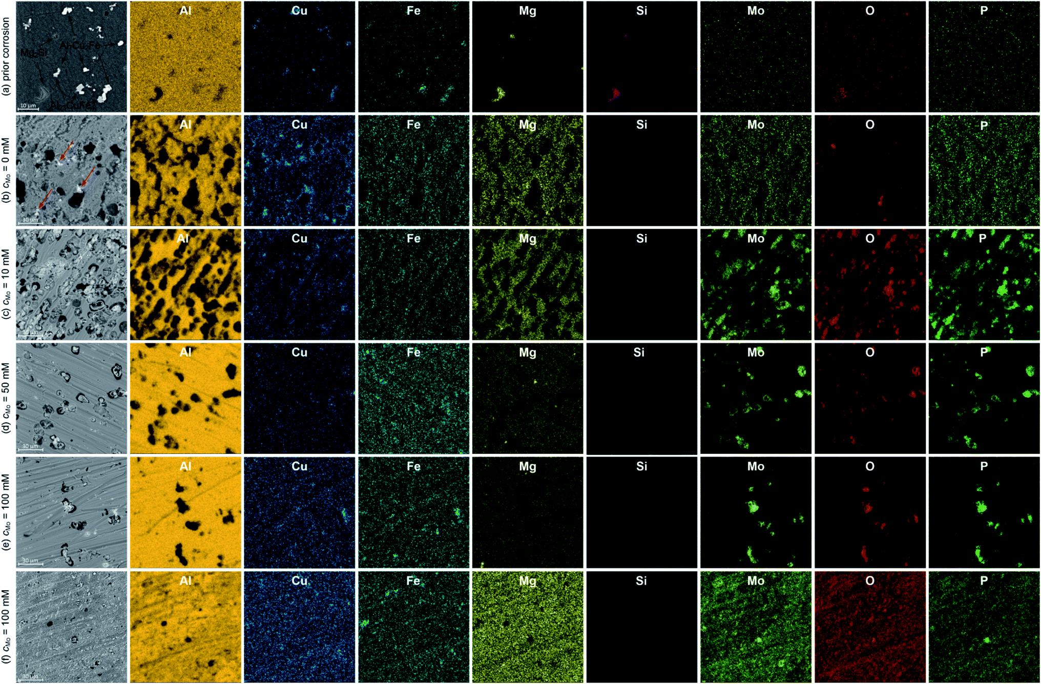 | ||
| Fig. 3 Microstructures of 7075 uncorroded (a) and corroded (b)–(f) specimens together with spatial distribution of elements, colour intensity differences on EDS maps occur due to different concentration of elements; for cMo = 100 mM two areas are depicted: (e) and (f), t = 580 min, T = 303. | ||
Microscopic analysis of the surfaces of corroded specimens revealed a corrosion mechanism and confirmed the inhibiting ability of sodium molybdate. The most severe corrosion was observed when cMo = 0 mM (Fig. 3b). Trenching around Al7Cu2Fe and Al23CuFe4 particles occurred. Excessive trenching caused mechanical detachment of these particles and their dissolution in the aerated electrolyte. Subsequently, copper ions reduced on the surface forming additional cathodic sites.33–35 They are indicated with red arrows in Fig. 3b. Deep corrosion pits remained on the surface, where originally aforementioned intermetallic particles were located. Corrosion attack occurred also to some extent at grain boundaries. This probably is related to dissolution of very fine MgZn2 particles. They are anodic with respect to the matrix and precipitated within the grains in the grain boundary zones during artificial aging.36
When cMo = 10 mM, copper particles were hardly observed on the surface (Fig. 3c). The number of deep corrosion pits as well as their diameter decreased when compared to the uninhibited solution. Trenching around Al7Cu2Fe and Al23CuFe4 intermetallics was partially hindered due to precipitation of Mo, P and O-rich salt. However significant number of shallow pits appeared. This may indicate that the Cu-containing intermetallics stopped serving as efficient cathodes in the corrosion cells. Thus, further depolarisation occurred within the matrix. This explains why precipitation of Mo, P and O-rich salt occurred not only on the surface of Al7Cu2Fe and Al23CuFe4 intermetallics, but also on the matrix.
When cMo = 50 mM corrosion rate was further decreased. Trenching occurred to much lesser extent when compared to uninhibited solution, Mo, P and O-rich particles were found only on the surface of Al7Cu2Fe and Al23CuFe4 intermetallics. Some shallow pits, but much less than for cMo = 10 mM were also observed (Fig. 3d). This suggests adsorption of heteropolyoxomolybdate/phosphomolybdenum blue species on the surface and further mitigation of matrix dissolution.
The lowest corrosion rate was achieved when cMo = 100 mM. Localised corrosion was mostly supressed; high concentration of heteropolyoxomolybdate/phosphomolybdenum blue species in the solution ensured sufficient matrix protection (Fig. 3e). At the same time, such a high initial concentration of heteropolyoxomolybdate caused local precipitation of Mo, P and O-rich layer on the surface. Uniform distribution of these elements was revealed (Fig. 3f). Such a local precipitation of insoluble salt in the form of protective layers was also observed on 1050 and 2024 alloys.15,16
3.3. X-ray photoelectron spectroscopy
Further examination of Mo, P and O-rich layer, obtained at cMo = 100 mM, was performed in three regions using X-ray photoelectron spectroscopy (XPS). Chemical composition of the layer is rather inhomogeneous (Table 2). Significant contribution from carbon C 1s, not shown in the table, was also detected because specimens were rinsed with isopropyl alcohol after exposition in the corrosive environment. The layer's phase composition is also inhomogeneous (Table 3). Oxygen exists both in the form of an oxide and salt. There are areas on the specimen, where either oxide or salt phase is dominant. Two oxidation states of molybdenum, V and VI were detected (Fig. 4a and b),37 there is also contribution from Al(III) and P(V).| Measurement | O | Al | P | Mo |
|---|---|---|---|---|
| Area 1 | 75.3 | 5.7 | 6.7 | 12.3 |
| Area 2 | 82.8 | 5.2 | 4.2 | 7.8 |
| Area 3 | 79.9 | 0.0 | 5.3 | 14.8 |
| Measurement | O 1s | Al 2p | P 2p | Mo 3d5/2 | ||
|---|---|---|---|---|---|---|
| O salt | O oxide | Al(III) | P(V) | Mo(V) | Mo(VI) | |
| Area 1 | 23.1 | 61.5 | 3.3 | 4.4 | 1.5 | 6.2 |
| Area 2 | 52.3 | 24.7 | 4.8 | 6.1 | 2.1 | 10.0 |
| Area 3 (pre-sputtered) | 58.5 | 15.4 | 5.4 | 8.6 | 0.5 | 11.6 |
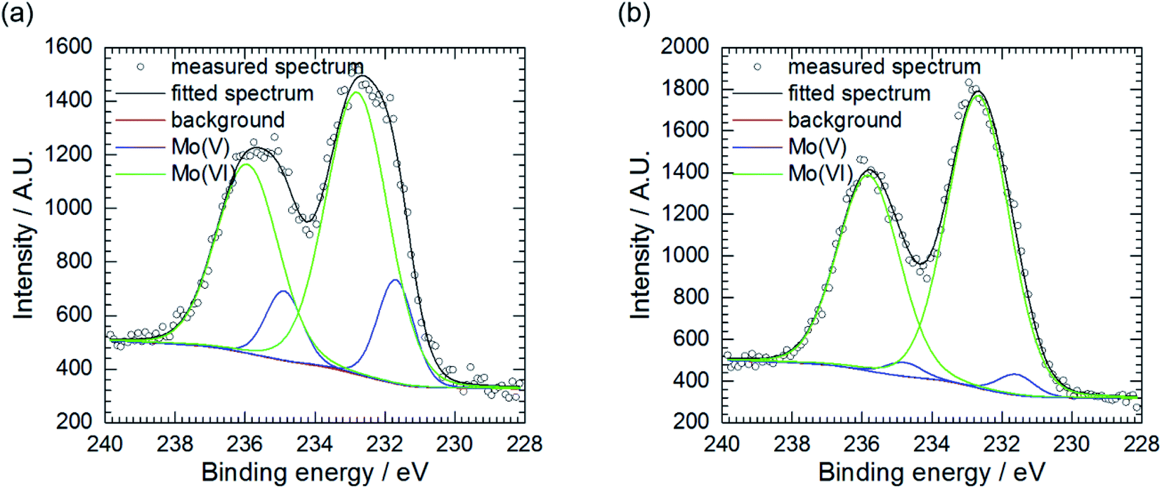 | ||
| Fig. 4 Mo 3d5/2 XPS spectra of corrosion layer obtained at cMo = 100 mM: (a) as obtained, area 2 and (b) area 3, pre-sputtered with Ar clusters. | ||
Pre-sputtering of the specimen with Ar clusters revealed that Mo(V) is mainly located on the surface of the corrosion layer, whereas Mo(VI) was found both on its surface and in the interior (Table 3, Fig. 4a and b). Thus, this layer can be composed of MoO3 with possible certain degree of non-stoichiometry. This is related to a partial reduction of Mo(VI) to Mo(V). The oxide colouration may then become grayish.38
Another possibility is formation of a molybdenum bronze on the surface. This term refers to a variety of ternary oxide phases containing molybdenum at V and VI oxidation state and small cations such as Li+, Na+, K+, Rb+, Cs+ and H+. These compounds exhibit intense colouration, metallic or semiconducting properties and resistance to attack by non-oxidising acids. The examples of molybdenum bronzes that could be formed during corrosion are H0.34MoO3 and H0.93MoO3. The colour of hydrogen molybdenum bronzes depends on the amount of incorporated oxygen.39
Presence of Al(III) and P(V) in the pre-sputtered area indicate their incorporation to the corrosion layer, probably in the form of a salt.
The surface of the corrosion layer is composed of molybdenum at both oxidation states, oxygen and phosphorus. This may correspond to phosphomolybdenum blue species adsorbed on the surface of the corrosion layer. Al(III) content might be related to aluminium adsorption or precipitation in the form of a salt.
The XPS study conducted is rather qualitative than quantitative i.e. the stoichiometry of the corrosion product could not be established. The studied system is very complex, numerous oxides and salts can be formed, they are also inhomogeneously distributed on the surface. Due to their small amount they were not detected during X-ray diffraction analysis. Thus, the mechanism of formation of the corrosion layer cannot be proposed. It should also be noted here that it depends on the concentration of heteropolyoxomolybdate species in the solution.
3.4. Electrochemical analysis
 | ||
| Fig. 5 Open circuit potential of 7075 aluminium alloy as a function of immersion time and initial concentration of sodium molybdate (a) and corrosion potential (b); 0.5 M H3PO4, T = 303 K. | ||
Corrosion potential Ecorr was estimated as the average of OCP values measured for the last 40 min of immersion. Corrosion potentials obtained from independent measurements were then averaged and uncertainties of obtained values were calculated using eqn (3). It can be concluded that Ecorr does not depend on cMo (Fig. 5b).
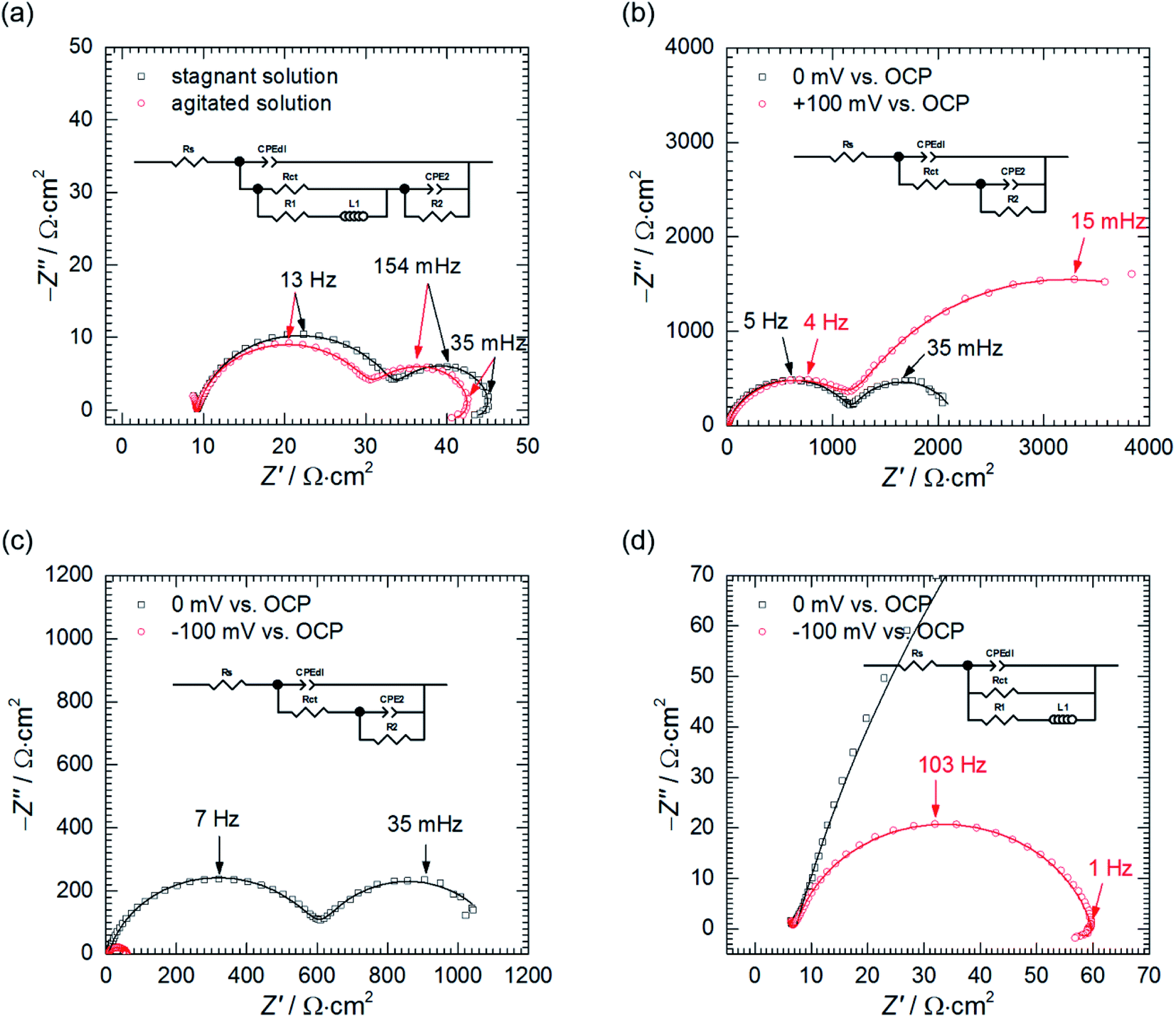 | ||
| Fig. 6 Impedance spectra of 7075 aluminium alloy obtained: (a) at OCP in the stagnant and agitated solutions when cMo = 0 mM,; (b) at η = 0 and +100 mV vs. OCP in the stagnant solution when cMo = 100 mM; (c) at η = 0 and −100 mV vs. OCP in the stagnant solution when cMo = 100 mM; (d) and their magnified high frequency parts; empty markers represent data points, continuous lines fit obtained using the EEC; 0.5 M H3PO4, T = 303 K. | ||
Such an EEC was introduced by Cao for three potential-dependent electrode processes, but he used a capacitor instead of the constant phase element CPE2.
The first one of these three processes is the charge transfer, whose rate directly depends on the electrode's potential. High frequency capacitive loops in the EIS spectra correspond to the constant phase element CPEdl, representing the double layer capacitance, connected in parallel to Rct.
The other ones could be adsorption of two different species, where a surface coverage depends on electrode's potential.40 They are visible in the obtained EIS spectra as the low-frequency capacitive and inductive loops. These adsorption processes are modelled using R1, R2, L1 and CPE2. Unfortunately, their physical meaning is far more complex than CPEdl and Rct. According to Cao, they depend on changes of faradaic current and adsorption kinetics related to changes in surface coverage and electrode potential for both adsorbing species. What is more, they are mutually related.40
The low frequency capacitive loop can probably be related to adsorption of atomic hydrogen onto electrode's surface.27 The low frequency inductive loop, in turn, might be attributed to adsorption of intermediates formed during Al dissolution. This was observed in non-aqueous41 and aqueous alkaline solutions.42 In acidic solutions, however, the charge transfer is believed to be too rapid to observe formation of intermediates.41 Thus, the origin of the small inductive loop is different and was ascribed to the presence of gas bubbles on the electrode's surface. This was concluded after conducting the following experiment. First, the impedance spectrum of aluminium alloy was recorded after t = 580 min of immersion in a stagnant solution. Then, agitation using a magnetic stirrer was started. When OCP again achieved stationary value, the impedance spectrum was measured and these two spectra were compared (Fig. 6a, Table 4). Double layer capacitances were calculated using eqn (5) and Cdl = 396 μF cm−2 was obtained for the stagnant solution. This value is relatively high when compared to the ideal one 20 μF cm−2.43 The reason for this is increased surface area of the corroded electrode (see Fig. 3b).
| Conditions | S | Rs Ω cm2 | Tdl μF sα−1·cm−2 | αdl | Rct Ω cm2 | R1 Ω cm2 | L1 H cm2 | T2 mF sα−1·cm−2 | α2 | R2 Ω cm2 |
|---|---|---|---|---|---|---|---|---|---|---|
| cMo = 0 mM, η = 0 mV, stagnant solution | 0.04 | 9(1) | 829(12) | 0.88(0.01) | 25(1) | 161(18) | 2015(452) | 84.5(1.6) | 0.97(0.02) | 12(1) |
| cMo = 0 mM, η = 0 mV, agitated solution | 0.04 | 9(1) | 971(16) | 0.87(0.01) | 22(1) | 88(9) | 1236(221) | 79.1(1.5) | 0.92(0.02) | 13(1) |
| cMo = 100 mM, η = 0 mV, stagnant solution | 0.12 | 8(1) | 39(1) | 0.86(0.01) | 1210(7) | N.A. | N.A. | 3549(125) | 0.94(0.02) | 955(25) |
| cMo = 100 mM, η = +100 mV, stagnant solution | 0.05 | 7(1) | 50(1) | 0.83(0.01) | 1240(7) | N.A. | N.A. | 1572(21) | 0.81(0.01) | 4076(95) |
| cMo = 100 mM, η = 0 mV, stagnant solution | 0.11 | 7(1) | 66(1) | 0.84(0.01) | 620(4) | N.A. | N.A. | 6589(236) | 0.92(0.02) | 496(17) |
| cMo = 100 mM, η = −100 mV, stagnant solution | 0.12 | 7(1) | 84(1) | 0.85(0.01) | 53(1) | 945(107) | 5720(797) | N.A. | N.A. | N.A. |
In fact, for certain alloys, when selective corrosion occurs, the increase of electrode's surface area is such high that double layer capacitance achieves several to hundreds of mF cm−2.43–46 Agitation increased Cdl to 463 μF cm−2. This occurred because agitation facilitated liberation of H2 bubbles from the surface and aqueous solutions have much higher electric permittivity than gases. A slight decrease of the charge transfer resistance can be related to increase of the surface area caused by liberation of H2 bubbles.
Agitation changed the parameters describing the second capacitive loop i.e. T2, α2 and R2 insignificantly. This is reasonable because, at the stationary state, agitation does not affect the adsorption processes.
Thus, the only possible explanation for ca. two-fold reduction in values of R1 and L1 in agitated solution seem to be H2 bubbles' liberation. The inductive loop cannot be solely related to adsorption, as it was proposed on the basis of Cao's model, because agitation does not affect adsorption processes at the stationary state. It has also nothing to do with diffusion because the imaginary part of the impedance related to diffusion is always negative.27
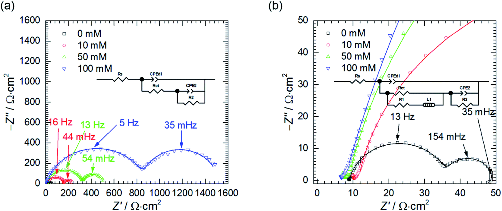
Second, the impedance spectra when cMo = 100 mM were analysed. These were measured after t = 580 min at the open circuit potential and consist of two capacitive loops (Fig. 6b and c). The first one, with frequency at the maximum apex 5–7 Hz corresponds to the double layer capacitance coupled with the charge transfer resistance. The other one, with frequency at the maximum apex ca. 35 mHz, is related to the potential-dependent adsorption process.47 Adsorbing species are probably heteropolyoxomolybdate or phosphomolybdenum blue.
When the spectrum at OCP was recorded, the electrode was polarised, η = ± 100 mV vs. OCP. After the potential achieved the stable value, EIS spectra were recorded (Fig. 6b–d) and fitted using appropriate EECs' (Table 4).
Significant discrepancy between Tdl, Rct, T2 and R2 fitted from both spectra registered at OCP can be observed. This is related to the corrosion itself, neither to the non-stationarity of the process nor to the fitting, and will be explained further in the text.
Anodic polarisation of the electrode did not significantly affect the double layer capacitance. Cdl calculated at OCP is between 10 and 16 μF cm−2 whereas, at η = + 100 mV, it equals to 10 μF cm−2. These values are slightly lower than theoretical value of 20 μF cm−2, probably due to adsorption of corrosion inhibitor onto the electrode. Rct obtained at OCP is 25–48-fold higher when compared to the solution without heteropolyoxomolybdates due to the same reason. When the electrode was polarised, charge transfer resistance increased only slightly. Rct takes into account two electrochemical processes: aluminium oxidation and reduction of heteropolyoxomolybdate to phosphomolybdenum blue. The latter is still possible at the applied overpotential (Fig. 7).
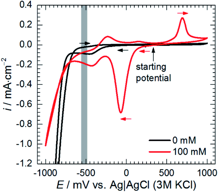 | ||
| Fig. 7 Cyclic voltammograms of 0.5 M H3PO4 solutions containing sodium molybdate, cMo = 0 and 100 mM, obtained for glassy carbon working electrode at scan rate 20 mV s−1, grey zone indicates OCP range obtained for cMo = 100 mM, T = 303 K. | ||
Anodic polarisation facilitates aluminium oxidation and impedes heteropolyoxomolybdate reduction. If phosphomolybdenum blue species were responsible for corrosion inhibition, aluminium oxidation would be facilitated and Rct decrease. Charge transfer resistance, however, remained virtually unchanged. What is more, polarisation resistance, calculated as the sum of Rct and R2, increased significantly from 2165 Ω cm2 to 5316 Ω cm2.
This was caused by the increase of R2 upon electrode's polarisation. It occurs when: (i) increasing electrode's potential causes increase of the adsorption rate, (ii) faradaic current decreases with increasing surface coverage, (iii) charge transfer resistance increases. These also result in decreasing the capacitance contributing to the faradaic impedance in Cao's model.47 In this work CPE2 corresponds to this capacitor and its parameter T2 indeed decreased. In the light of these results, heteropolyoxomolybdate species can be regarded as the corrosion inhibitor in the studied system. Their reduction to phosphomolybdenum blue is then detrimental because seems to be followed by its desorption and exposition of the metal.
Cathodic polarisation, in turn, resulted in the slight increase of the double layer capacitance to 22 μF cm−2, significant decrease of the charge transfer resistance, disappearance of the low-frequency capacitive loop and appearance of the small, inductive one. Rct determined at η = 0 and −100 mV takes into account reduction of H3O+ to H2, heteropolyoxomolybdate to phosphomolybdenum blue and O2 to H2O. Cathodic polarisation facilitates charge transfer in all these cases, thus, significant decrease of Rct was obtained when compared to η = 0 mV. Reduction of heteropolyoxomolybdate occurs in two, virtually irreversible steps at ca. −65 and −430 mV vs. Ag|AgCl (3 M KCl) reference electrode. Phosphomolybdenum blue species are oxidised during the reverse scan at −237, +148 and +691 mV vs. Ag|AgCl (3 M KCl). These potential values were obtained on the glassy carbon working electrode and may differ in the case of aluminium alloy. Lower value of Rct obtained at η = −100 mV when compared to η = +100 mV means that heteropolyoxomolybdate is the anodic corrosion inhibitor.
Basing on these results the influence of heteropolyoxomolybdate/phosphomolybdenum blue species on the kinetics of hydrogen evolution cannot be determined. Cathodic polarisation facilitates hydrogen evolution, thus, the low-frequency capacitive loop, ascribed to atomic hydrogen adsorption, disappeared. At the same time, a small, inductive loop previously related to the presence of gas bubbles on the surface appeared (Fig. 6d).
The influence of cMo on the impedance spectra obtained at OCP was also studied (Fig. 8). When cMo = 10 mM the inductive loop at the lowest frequencies, observed at cMo = 0 mM disappeared, because such a concentration of heteropolyoxomolybdate is sufficient to significantly reduce the amount of evolving hydrogen.15,16 This confirms the aforementioned hypothesis of the nature of the inductive loop. Further increase of cMo causes the increase of the impedance which stays in a good agreement with Fig. 1.
 | ||
| Fig. 8 Selected impedance spectra of 7075 aluminium alloy obtained at η = 0 mV, in the stagnant solution, as a function of cMo (empty markers) fitted using the EEC, (continuous lines) (a) and their magnified high frequency parts with EEC used for fitting when cMo = 0 mM (b); 0.5 M H3PO4, T = 303 K, t = 580 min. | ||
Resistances Rct and R2 increase as the concentration of heteropolyoxomolybdate increases, whereas T2 decreases. As it was already discussed, such a behaviour is related to increase of the charge transfer resistance, which was clearly observed, and decrease of the faradaic current caused by increasing surface coverage.47
Double layer capacitance decreases as cMo increases from 383 ± 8 μF cm−2 to 15 ± 4 μF cm−2 (Fig. 9a). The former, relatively high value, is related to high surface area of the electrode after corrosion process. This decreases with increasing inhibitor concentration to the values typical for double layer capacitance of the metallic electrodes.
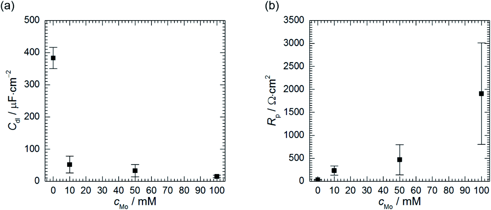 | ||
| Fig. 9 Double layer capacitance (a) and polarisation resistance (b) as a function of cMo, 0.5 M H3PO4, T = 303 K, t = 580 min. | ||
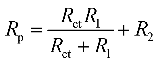
Corrosion rate is directly related to the polarisation resistance Rp, which is defined as the faradaic impedance when ω → 0 Hz. It was calculated using eqn (6) when cMo = 0 mM and eqn (7) when cMo > 0 mM (Fig. 9b):
 | (6) |
| Rp = Rct + R2 | (7) |
Polarisation resistance increases with increasing concentration of heteropolyoxomolybdate species. It is interesting to observe that its uncertainty increases as the Rp increases and is high at cMo = 100 mM. Relatively high uncertainties were also observed for Rct, R2 and T2 when cMo > 10 mM (Table 5). Evans explained that such a behaviour is related to the surface area of the specimen. When it is relatively small, decreasing corrosion rate causes a significant increase of the discrepancies between independent measurements.48 This was not observed in Fig. 1 because the surface area of the specimens was 2-fold higher when compared to the electrodes prepared for electrochemical tests.
| cMo mM | n | Rs Ω cm2 | Tdl μF sα−1·cm−2 | αdl | Rct Ω cm2 | R1 Ω cm2 | L1 H cm2 | T2 mF sα−1·cm−2 | α2 | R2 Ω cm2 |
|---|---|---|---|---|---|---|---|---|---|---|
| 0 | 3 | 9(1) | 739(269) | 0.89(0.04) | 26(3) | 219(170) | 2505(2679) | 110(101) | 0.99(0.04) | 11(5) |
| 10 | 4 | 11(2) | 122(61) | 0.89(0.01) | 165(74) | 55(25) | 0.98(0.05) | 68(27) | ||
| 50 | 4 | 8(1) | 91(52) | 0.88(0.01) | 266(190) | 24(20) | 0.98(0.06) | 147(140) | ||
| 100 | 6 | 7(1) | 56(19) | 0.85(0.01) | 1000(621) | 6(4) | 0.92(0.04) | 907(795) |
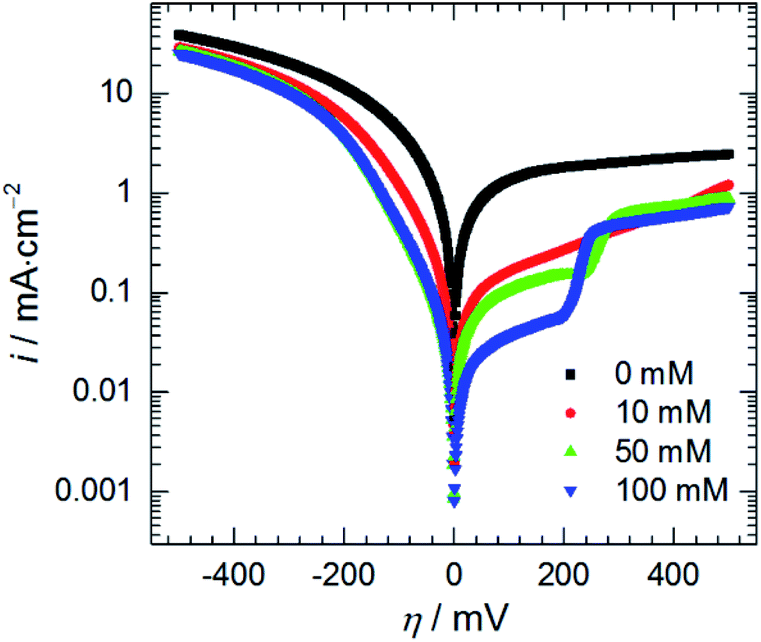 | ||
| Fig. 10 Anodic and cathodic polarisation curves as a function of initial concentration of heteropolyoxomolybdate species, 0.5 M H3PO4, T = 303 K, scan rate 15 mV min−1. | ||
Adsorption of heteropolyoxomolybdate species caused significant decrease of the anodic current density. This confirms that heteropolyoxomolybdate is anodic inhibitor. When cMo ≥ 50 mM, sharp increase of current density around η = 200 mV occurred. This corresponds to oxidation peak of phosphomolybdenum blue at −237 mV vs. Ag|AgCl|3 M KCl.
4. Conclusions
Sodium molybdate, when dissolved in orthophosphoric acid aqueous solution forms heteropolyoxomolybdate species. They significantly decrease the corrosion rate of 7075 alloy from 75.98 to 3.24 g per m2 per day. Obtained results suggest that even higher inhibition efficiency could be obtained at the higher concentration of sodium molybdate. The influence of temperature on the corrosion rate and inhibition efficiency of 7075 alloy should be further studied.The mechanism of corrosion inhibition in Na2MoO4–H3PO4–Al system was established. Heteropolyoxomolybdate species adsorb on the surface of the alloy and hamper aluminium oxidation process. This manifests as a significant increase of the charge transfer resistance and polarisation resistance. Anodic polarisation, at certain range of potential, facilitates the adsorption of heteropolyoxomolybdate. When its reduction to phosphomolybdenum blue is hampered, higher inhibition efficiency can be obtained. It was shown that trenching around Al7Cu2Fe and Al23CuFe4 intermetallic particles, that are more noble than the matrix, does not occur at sufficiently high initial concentration of Na2MoO4. At the same time, heteropolyoxomolybdate inhibits cathodic process, but much weaker when compared to the anodic one. This is probably achieved due to precipitation of an insoluble salt, containing Mo, P and O, onto intermetallic particles.
Conflicts of interest
There are no conflicts to declare.Acknowledgements
The financial support from the National Science Centre, Poland, Grant No. 2016/23/D/ST5/01343 is gratefully acknowledged. The author also acknowledge Dr Barbara Kościelniak for her help in microscopic investigations, Dr Magdalena Wytrwał-Sarna for XPS characterisation of the corrosion products and Mr Andrzej Obłój for his help in conducting corrosion tests.References
- C. Vargel, Corrosion of Aluminium, Elsevier B.V, Amsterdam, 2004 Search PubMed.
- E. A. Starke and J. T. Staley, Progress in Aerospace Sciences, 2010, 32, 131–172 CrossRef.
- A. Bozza, R. Giovanardi, T. Manfredini and P. Mattioli, Surf. Coat. Technol., 2015, 270, 139–144 CrossRef CAS.
- G. Sabatini, L. Ceschini, C. Martini, J. A. Williams and I. M. Hutchings, Mater. Des., 2010, 31, 816–828 CrossRef CAS.
- P. G. Sheasby, R. Pinner and S. Wernick, The surface treatment and finishing of aluminium and its alloys, ASM International, Trowbridge, 2001 Search PubMed.
- S. A. Katz and H. Salem, J. Appl. Toxicol., 1993, 13, 217–224 CrossRef CAS PubMed.
- S. A. Umoren, Y. Li and F. H. Wang, J. Solid State Electrochem., 2010, 14, 2293–2305 CrossRef CAS.
- K. Xhanari and M. Finšgar, RSC Adv., 2016, 6, 62833–62857 RSC.
- A. Y. El-Etre, Corros. Sci., 2001, 43, 1031–1039 CrossRef CAS.
- M. A. Amin, Q. Mohsen and O. A. Hazzazi, Mater. Chem. Phys., 2009, 114, 908–914 CrossRef CAS.
- A. I. Ali and N. Foaud, J. Mater. Environ. Sci., 2012, 3, 917–924 CAS.
- E. E. Oguzie, Corros. Sci., 2007, 49, 1527–1539 CrossRef CAS.
- X. Li, S. Deng and H. Fu, Corros. Sci., 2011, 53, 2748–2753 CrossRef CAS.
- W. A. Badawy and F. M. Al-Kharafi, Corros. Sci., 1997, 39, 681–700 CrossRef CAS.
- P. Kwolek, A. Kamiński, K. Dychtoń, M. Drajewicz and J. Sieniawski, Corros. Sci., 2016, 106, 208–216 CrossRef CAS.
- K. Dychtoń and P. Kwolek, Corros. Eng., Sci. Technol., 2018, 53, 234–240 CrossRef.
- P. Kwolek and M. Wojnicki, Corros. Eng., Sci. Technol., 2018, 54, 199–204 Search PubMed.
- M. T. Pope, Heteropoly and Isopoly Oxometalates, Springer-Verlag, Berlin, 1983 Search PubMed.
- B. Krebs, K. H. Tytko, J. Mehmke and S. Stiller, Eur. J. Solid State Inorg. Chem., 1991, 28, 883–903 CAS.
- A. Müller, E. Krickemeyer, J. Meyer, H. Bögge, F. Peters, W. Plass, E. Diemann, S. Dillinger, F. Nonnenbruch and M. Randerath, Angew. Chem., 1995, 107, 2293–2295 CrossRef.
- A. Müller, B. Botar, S. K. Das, H. Bögge, M. Schmidtmann and A. Merca, Polyhedron, 2004, 23, 2381–2385 CrossRef.
- E. A. Nagul, I. D. McKelvie, P. Worsfold and S. D. Kolev, Anal. Chim. Acta, 2015, 890, 60–82 CrossRef CAS PubMed.
- P. Kwolek, A. Pustuła and W. J. Nowak, Surf. Coat. Technol., 2019, 357, 535–542 CrossRef CAS.
- D. A. Skoog, D. M. West, F. J. Holler and S. R. Crouch, Fundamentals of Analytical Chemistry, Cengage Learning, 2013 Search PubMed.
- B. Boukamp, J. Electrochem. Soc., 1995, 142, 1885–1894 CrossRef CAS.
- B. Boukamp, Solid State Ionics, 2004, 169, 65–73 CrossRef CAS.
- A. Lasia, Electrochemical impedance spectroscopy and its applications, Springer, New York, USA, 2014 Search PubMed.
- M. S. Kaba, I. K. Song, D. C. Duncan, C. L. Hill and M. A. Barteau, Inorg. Chem., 1998, 37, 398–406 CrossRef CAS PubMed.
- J. Goldstein, D. E. Newbury, P. Echlin, D. C. Joy, A. D. Roming, C. E. Lyman, C. Fiori and E. Lifshin, Scanning Electron Microscopy and X-Ray Microanalysis, Plenum Press, New York, USA, 2nd edn, 1992 Search PubMed.
- F. Andreatta, H. Terryn and J. H. W. de Wit, Corros. Sci., 2003, 45, 1733–1746 CrossRef CAS.
- M. Gao, C. R. Feng and R. P. Wei, Metall. Mater. Trans. A, 1998, 29, 1145–1151 CrossRef.
- R. P. Wei, C. M. Liao and M. Gao, Metall. Mater. Trans. A, 1998, 29, 1153–1160 CrossRef.
- H. M. Obispo, L. E. Murr, R. M. Arrowood and E. A. Trillo, J. Mater. Sci., 2001, 36, 3479–3495 CrossRef.
- M. B. Vukmirovic, N. Dimitrov and K. Sieradzki, J. Electrochem. Soc., 2002, 149, B428 CrossRef CAS.
- R. G. Buchheit, M. A. Martinez and L. P. Montes, J. Electrochem. Soc., 2000, 147, 119–124 CrossRef CAS.
- F. Andreatta, H. Terryn and J. H. W. De Wit, Electrochim. Acta, 2004, 49, 2851–2862 CrossRef CAS.
- J. Baltrusaitis, B. Mendoza-Sanchez, V. Fernandez, R. Veenstra, N. Dukstiene, A. Roberts and N. Fairley, Appl. Surf. Sci., 2015, 326, 151–161 CrossRef CAS.
- I. A. de Castro, R. S. Datta, J. Z. Ou, A. Castellanos-Gomez, S. Sriram, T. Daeneke and K. Kalantar-zadeh, Adv. Mater., 2017, 29, 1–31 CrossRef PubMed.
- M. Greenblatt, Chem. Rev., 1988, 88, 31–53 CrossRef CAS.
- C. Cao, Electrochim. Acta, 1990, 35, 837–844 CrossRef CAS.
- L. Péter, J. Arai and H. Akahoshi, J. Electroanal. Chem., 2000, 482, 125–138 CrossRef.
- D. D. Macdonald, K. H. Lee, A. Moccari and D. Harrington, Corrosion, 1988, 44, 652–657 CrossRef CAS.
- L. Chen and A. Lasia, J. Electrochem. Soc., 1992, 139, 3214–3219 CrossRef CAS.
- L. Chen and A. Lasia, J. Electrochem. Soc., 1993, 140, 2464–2473 CrossRef CAS.
- P. Kwolek, K. Dychtoń and M. Pytel, J. Solid State Electrochem., 2019, 23, 3019–3029 CrossRef CAS.
- P. Kwolek, B. Kościelniak and M. Wytrwal-Sarna, Materials, 2020, 13, 1946 CrossRef PubMed.
- C. Cao, Electrochim. Acta, 1990, 35, 831–836 CrossRef CAS.
- U. R. Evans, The corrosion and oxidation of metals, Edward Arnold Publishers Ltd., London, 1968 Search PubMed.
| This journal is © The Royal Society of Chemistry 2020 |