DOI:
10.1039/D0RA04211K
(Paper)
RSC Adv., 2020,
10, 25260-25265
Controlling crystal growth of MIL-100(Fe) on Ag nanowire surface for optimizing catalytic performance†
Received
11th May 2020
, Accepted 26th June 2020
First published on 2nd July 2020
Abstract
Ag/MIL-100(Fe) core/sheath nanowire with controllable thickness of the MIL-100(Fe) sheath was prepared by controlling the crystal growth of MIL-100(Fe) on the Ag nanowire surface. The evolution of the MIL-100(Fe) sheath monitored by transmission electron microscopy (TEM), scanning electron microscopy (SEM), powder X-ray diffraction (XRD), thermogravimetric analyses (TGA), X-ray photoelectron spectroscopy (XPS), fourier transform infrared spectroscopy (FT-IR), and N2 adsorption–desorption analysis indicates that the thickness of the MIL-100(Fe) sheath increases with the increasing number of crystal growth cycles of MIL-100(Fe) on the Ag nanowire surface. Catalytic reaction over Ag/MIL-100(Fe) core/sheath nanowire suggests that the thickness of the MIL-100(Fe) sheath largely influences the catalytic performance and it is quite important to control the crystal growth of MIL-100(Fe) on the Ag nanowire surface for optimizing catalytic performance.
Introduction
Metal–organic frameworks (MOFs), as a kind of promising porous crystals, are constructed by the coordination between metal ions and organic ligands.1–3 Taking advantage of porosity, high specific surface area, regulable structures, abundant components and easy post modification, MOFs are widely used in the research and applications of heterogeneous catalysis,4–6 chemical sensing,7–9 drug delivery,10,11 adsorption12–14 and separation.15,16
Recently, MOFs have been found to be a good matrix for noble metals, which are excellent catalysts for aromatization, isomerization, oxidation, dehydrogenation and hydrogenation reactions.17–20 Due to the robust porous frameworks, MOFs could not only protect noble metals from leaching or aggregating, but also provide transport pathway for reactants to approach the catalytic active sites of the noble metals inside MOFs crystals. In addition, synergistic effect is usually found between MOFs and noble metals in the MOFs-noble metals composites. For examples, it endows noble metals catalysts with size selectivity that MOFs permit the molecules of which the size is smaller than the pores windows but forbid the molecules of which the size is larger than the pores windows of MOFs to enter inside.21–24 As MOFs themselves can also act as catalysts, the combination of MOFs and noble metals also provide cascade catalysis.25–28 Taking advantage of the adsorption function of MOFs, the catalytic performance of noble metals is usually promoted through the enrichment of reactants by MOFs around the catalytic active sites of noble metals.29–31
From the view of that MOFs provide the synergistic effect to noble metals catalysts, controlled construction of well-defined MOFs-noble metals heterostructures is quite important. Indeed, increasing attentions have been focused on the distribution or size control of noble metals inside MOFs. For example, Lu and co-workers achieved controlled nanoparticle encapsulation inside ZIF-8 through a successive adsorption method.32 Zhu and co-workers simultaneously controlled the size and location of AuNi nanoparticles inside MIL-101 through the combination of double solvents method and liquid-phase concentration-controlled reduction strategy.33 However, to the best of our knowledge, most researches have been focused on noble metal nanoparticles, and few attentions are paid to noble metal nanowires. As noble metal nanowires have garnered a significant amount of research attention because of their unique electronic, optical, thermal, and catalytic properties,34,35 it is very interesting and promising to construct MOFs-noble metal nanowires heterostructures. In this work, we use a multiple growth method to control the crystal growth of MIL-100(Fe) on Ag nanowire surface to build well-defined Ag/MIL-100(Fe) core/sheath nanowire. The thickness of the MIL-100(Fe) sheath is adjusted by the crystal growth cycles of MIL-100(Fe) on Ag nanowire surface and thus achieve an optimizing catalytic performance of the Ag/MIL-100(Fe) core/sheath nanowire. Liquid phase catalytic reduction of 4-nitrophenol (4-NP) by NaBH4 to 4-aminophenol (4-AP) is chosen as the model reaction here to test the catalytic performance because the catalytic elimination of 4-NP is very important due to the serious damage of 4-NP to the living environment.
Results and discussion
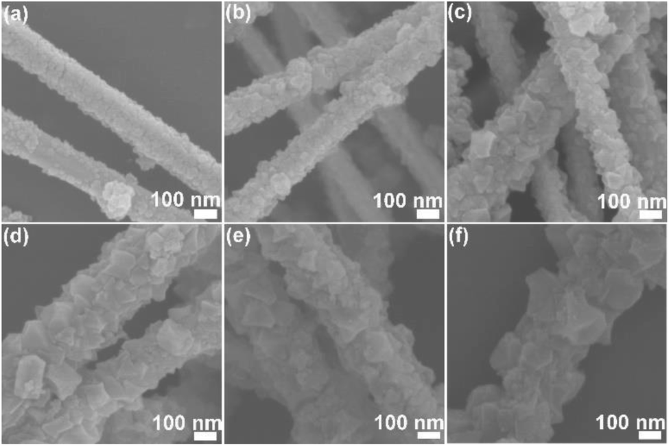
The morphology of the obtained Ag/MIL-100(Fe) core/sheath nanowire was investigated by SEM. Ag/MIL-100(Fe)-1, Ag/MIL-100(Fe)-3, Ag/MIL-100(Fe)-5, Ag/MIL-100(Fe)-7, Ag/MIL-100(Fe)-10, Ag/MIL-100(Fe)-15 represent the products obtained by repeat MIL-100(Fe) crystal growth on Ag nanowire surface with 1, 3, 5, 7, 10 and 15 cycles, respectively. From the observation of SEM (Fig. 1a–f), all the products show the typical nanowire form with large amounts of MIL-100(Fe) crystals covering on the surface. Under one crystal growth cycle of MIL-100(Fe), the MIL-100(Fe) crystals are too small and not enough to cover the surface of the Ag nanowire completely (Fig. 1a). With the number of MIL-100(Fe) crystal growth cycles increases, MIL-100(Fe) crystals could cover the surface of Ag nanowire completely and the surface of Ag/MIL-100(Fe) core/sheath nanowire approaches to the rougher due to the increase both in size and quantity of the MIL-100(Fe) crystals (Fig. 1b–f). Obviously, there are not only nucleation of new MIL-100(Fe) crystals but also growth of the already existed MIL-100(Fe) crystals on Ag nanowire surface in the process of repeated MIL-100(Fe) crystal growth cycles.
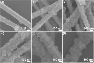 |
| | Fig. 1 SEM images of Ag/MIL-100(Fe)-1 (a), Ag/MIL-100(Fe)-3 (b), Ag/MIL-100(Fe)-5 (c), Ag/MIL-100(Fe)-7 (d), Ag/MIL-100(Fe)-10 (e), Ag/MIL-100(Fe)-15 (f). | |
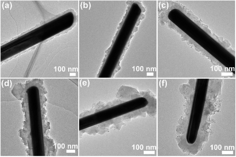
The core/sheath structure of the Ag/MIL-100(Fe) nanowire was studied by TEM. As illustrated in Fig. 2, Ag/MIL-100(Fe) nanowire presents a typical core/sheath structure with Ag nanowire core and MIL-100(Fe) crystals sheath. The thickness of the MIL-100(Fe) sheath become thicker and thicker (with average thickness of about 37, 44, 55, 73, 85 and 92 nm for Ag/MIL-100(Fe)-1, Ag/MIL-100(Fe)-3, Ag/MIL-100(Fe)-5, Ag/MIL-100(Fe)-7, Ag/MIL-100(Fe)-10 and Ag/MIL-100(Fe)-15, respectively) with increasing the repeated crystal growth cycles of the MIL-100(Fe) on Ag nanowire surface (Fig. 2a–f). In addition, the organizational form of MIL-100(Fe) crystals on Ag nanowire surface evolve obviously, from the fine and uniform sheath to the block and coarse sheath. However, there is no obvious change on the Ag nanowire core.
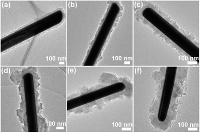 |
| | Fig. 2 TEM images of Ag/MIL-100(Fe)-1 (a), Ag/MIL-100(Fe)-3 (b), Ag/MIL-100(Fe)-5 (c), Ag/MIL-100(Fe)-7 (d), Ag/MIL-100(Fe)-10 (e), Ag/MIL-100(Fe)-15 (f). | |
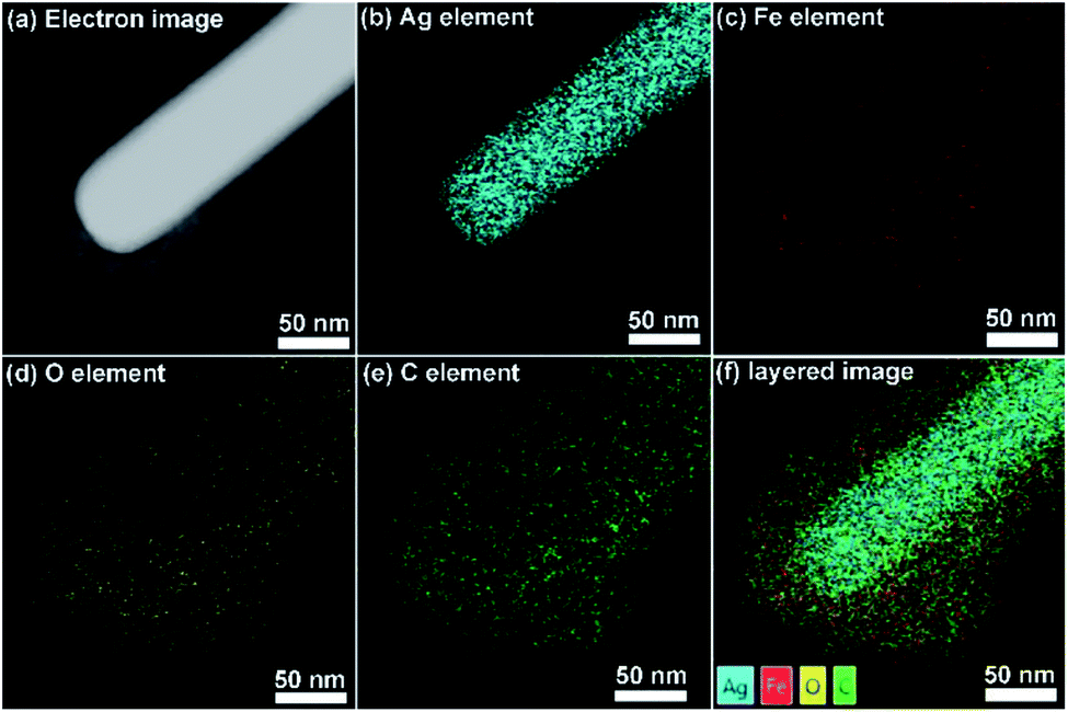
Ag/MIL-100(Fe)-5 is used here to analyze the composition of the Ag/MIL-100(Fe) core/sheath nanowire. As observed in the electron image (Fig. 3a), the brighter Ag nanowire due to the larger atomic mass centers in the core area accompanied with the pale MIL-100(Fe) sheath. In addition, the distribution of Ag element is clear and the boundary of the Ag core is obvious (Fig. 3b), suggesting the core composition is Ag. Furthermore, the distributions of Fe, O and C elements are quite similar as all of them are from the composition of MIL-100(Fe) (Fig. 3c–e). The elements of Fe, O and C distribute uniformly throughout the whole sheath area, rendering a typical sheath structure. Finally, EDX layered image clearly demonstrates the relations among Ag, Fe, O and C elements, evenly mixed elements of Fe, O and C sheath layer on the well-defined element of Ag core, suggesting a typical Ag/MIL-100(Fe) core/sheath nanowire with Ag nanowire core and MIL-100(Fe) sheath.
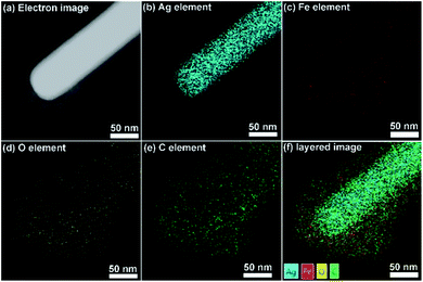 |
| | Fig. 3 Electron image, elemental mapping images and EDX layered image of Ag/MIL-100(Fe)-5. | |
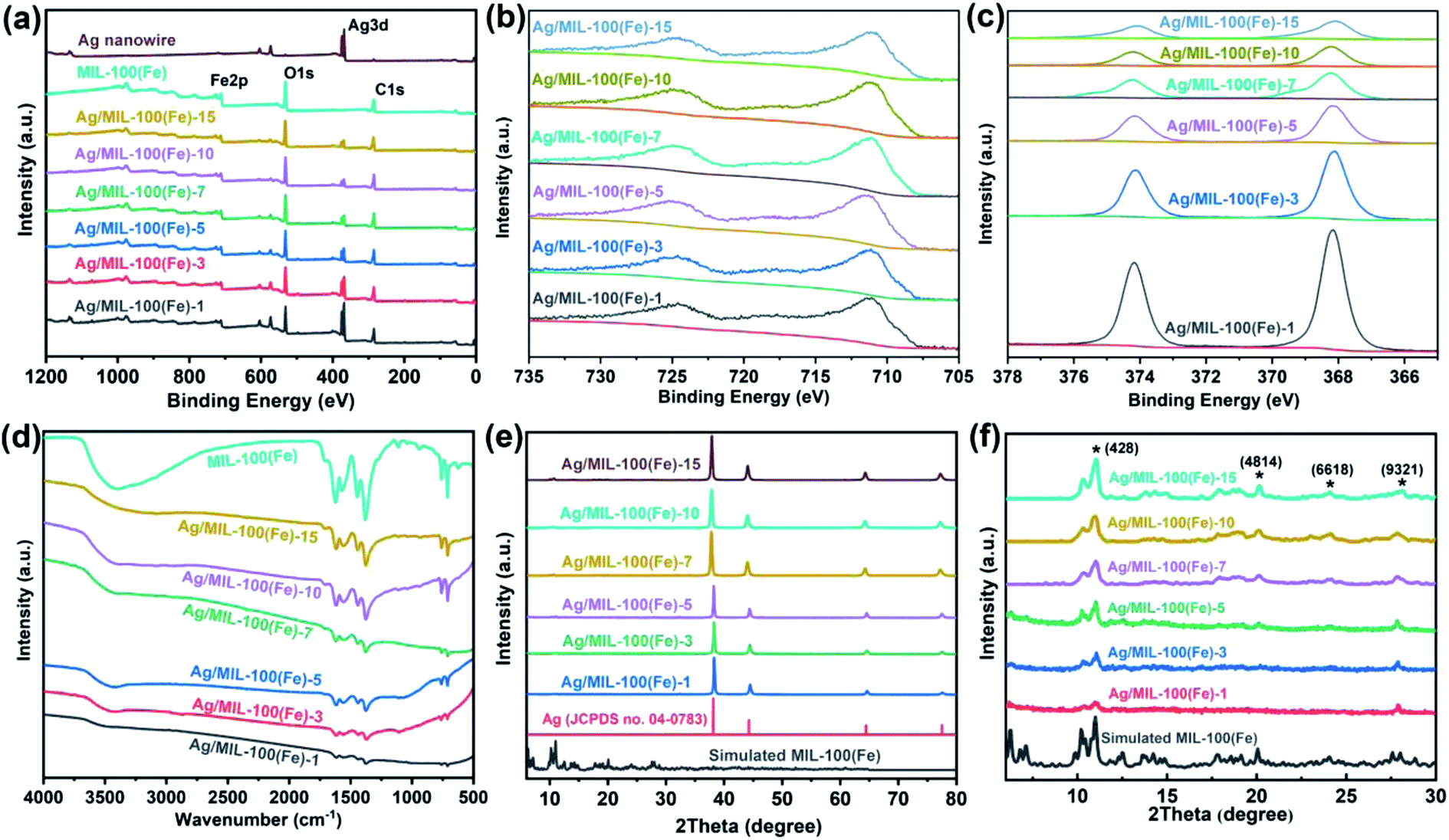
To further illustrate the chemical composition of the Ag/MIL-100(Fe) core/sheath nanowire, XPS, FT-IR and XRD analysis have also been employed (Fig. 4). As illustrated by the XPS spectra in Fig. 4a, the signals of C, O, Fe and Ag elements are clear in the surveys of 1200 to 0 eV. The two peaks at 711 eV and 725 eV can be assigned to 2p3/2 and 2p1/2 of Fe3+, respectively, which is associated with the MIL-100(Fe) sheath (Fig. 4b). The co-existence of Fe2+ and Fe3+ in Fe 2p3/2 peak indicated the residual of Fe2+ which was from the experimental materials (FeCl2) for constructing MIL-100(Fe). The binding energies of Ag 3d5/2 and Ag 3d3/2 are determined to be 368 and 374 eV, respectively, indicating the presence of the Ag nanowire core (Fig. 4c). The FT-IR peaks of the Ag/MIL-100(Fe) core/sheath nanowire are similar with that of MIL-100(Fe) crystals (Fig. 4d). The peak at 3000–3800 cm−1 is a typical peak of –OH arising from the moisture adsorbed in materials, indicating that the materials have porosity. C–H vibration peaks of benzene ring, arising from the organic ligand (trimesic acid) of MIL-100(Fe) sheath, are found by the presence of 760 cm−1 and 710 cm−1 peaks. The coordination between Fe3+ and oxygen atoms of the organic ligand is further proved and regarded as being with μ2–η1, η1 bridging mode, because of the finding of the symmetric and asymmetric vibration peaks of –COO− at 1375 cm−1 and 1625 cm−1. Moreover, the crystal phase compositions of the Ag/MIL-100(Fe) core/sheath nanowire were investigated by XRD (Fig. 4e and f). From the total observation in Fig. 4e, strong diffraction peaks associated with the standard Ag (JCPDS no. 04-0783) are detected, demonstrating good crystallinity of the Ag nanowire. To better define the diffraction peaks of MIL-100(Fe), a magnified figure of the XRD spectrum with a 2θ range of 5–30° is provided in Fig. 4f, in which the peaks at 11° (428), 20.1° (4814), 24° (6618), and 27.7° (9321) corresponding to the intrinsic MIL-100(Fe) crystals as reported previously are labelled with an “*”. The XRD spectra reveal that the Ag/MIL-100(Fe) core/sheath nanowire are composed of Ag and MIL-100(Fe) with distinct crystal structures.
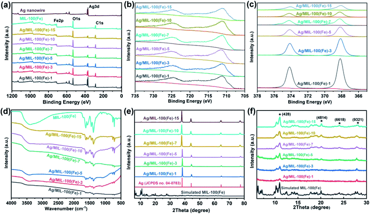 |
| | Fig. 4 XPS (a–c), FT-IR (d) and XRD (e and f) patterns of Ag/MIL-100(Fe)-1, Ag/MIL-100(Fe)-3, Ag/MIL-100(Fe)-5, Ag/MIL-100(Fe)-7, Ag/MIL-100(Fe)-10, Ag/MIL-100(Fe)-15, MIL-100(Fe) and Ag nanowire, respectively. | |
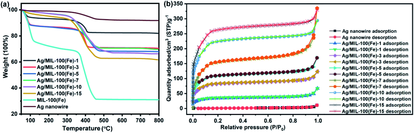
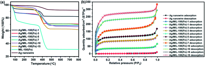
According to the TGA analysis, the weight percentage of MIL-100(Fe) in the Ag/MIL-100(Fe) core/sheath nanowire could be probably calculated. As illustrated in Fig. 5a, the first weight loss stage of Ag/MIL-100(Fe)-1, Ag/MIL-100(Fe)-3, Ag/MIL-100(Fe)-5, Ag/MIL-100(Fe)-7, Ag/MIL-100(Fe)-10 and Ag/MIL-100(Fe)-15 are associated with the release of free molecules, which could be moisture absorbed from the atmosphere or solvents used in the synthesis process. The second weight loss stage of Ag/MIL-100(Fe)-1, Ag/MIL-100(Fe)-3, Ag/MIL-100(Fe)-5, Ag/MIL-100(Fe)-7, Ag/MIL-100(Fe)-10 and Ag/MIL-100(Fe)-15 are associated with the decomposition of MIL-100(Fe), which are regarded as the host weight loss and the values are 10%, 14%, 16%, 25%, 28% and 30%, respectively, according to the curves. To facilitate the calculation of the weight percentage of MIL-100(Fe) in the Ag/MIL-100(Fe) core/sheath nanowire, host weight loss of Ag nanowire and MIL-100(Fe) are also introduced and calculated as 5% and 37%, respectively. The weight percentage of MIL-100(Fe) in the Ag/MIL-100(Fe) core/sheath nanowire is set equal to x, and the values are 16%, 28%, 34%, 63%, 72% and 78% for Ag/MIL-100(Fe)-1, Ag/MIL-100(Fe)-3, Ag/MIL-100(Fe)-5, Ag/MIL-100(Fe)-7, Ag/MIL-100(Fe)-10 and Ag/MIL-100(Fe)-15, respectively, calculated according to the following equations based on the host weight loss of each species:
| 5%(1 − x) + 37%x = 10% for Ag/MIL-100(Fe)-1 |
| 5%(1 − x) + 37%x = 14% for Ag/MIL-100(Fe)-3 |
| 5%(1 − x) + 37%x = 16% for Ag/MIL-100(Fe)-5 |
| 5%(1 − x) + 37%x = 25% for Ag/MIL-100(Fe)-7 |
| 5%(1 − x) + 37%x = 28% for Ag/MIL-100(Fe)-10 |
| 5%(1 − x) + 37%x = 30% for Ag/MIL-100(Fe)-15 |
 |
| | Fig. 5 TGA (a) and N2 adsorption–desorption (b) curves of Ag/MIL-100(Fe)-1, Ag/MIL-100(Fe)-3, Ag/MIL-100(Fe)-5, Ag/MIL-100(Fe)-7, Ag/MIL-100(Fe)-10, Ag/MIL-100(Fe)-15, MIL-100(Fe) and Ag nanowire, respectively. | |
The BET surface area of Ag/MIL-100(Fe)-1, Ag/MIL-100(Fe)-3, Ag/MIL-100(Fe)-5, Ag/MIL-100(Fe)-7, Ag/MIL-100(Fe)-10 and Ag/MIL-100(Fe)-15 are about 121.78 m2 g−1, 301.10 m2 g−1, 409.62 m2 g−1, 688.02 m2 g−1, 812.24 m2 g−1 and 939.80 m2 g−1, respectively. Evidently, the BET surface area of Ag/MIL-100(Fe) core/sheath nanowire increases with the increasing of the crystal growth cycles of MIL-100(Fe) on Ag nanowire surface, as the porous MIL-100(Fe) plays the key role in the BET surface area. N2 adsorption–desorption isotherms of Ag/MIL-100(Fe)-1, Ag/MIL-100(Fe)-3, Ag/MIL-100(Fe)-5, Ag/MIL-100(Fe)-7, Ag/MIL-100(Fe)-10 and Ag/MIL-100(Fe)-15 stay the same, in which the co-existence of type I and type IV isotherms indicates the co-existence of micropore and mesopore in the samples (Fig. 5b).
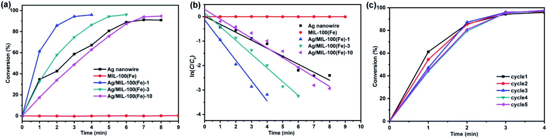
Ag/MIL-100(Fe)-1, Ag/MIL-100(Fe)-3, Ag/MIL-100(Fe)-10, MIL-100(Fe) and Ag nanowire were selected to investigate the catalytic reaction of 4-nitrophenol (4-NP) reduction by NaBH4 to 4-aminophenol (4-AP). From the observation in Fig. 6a, a conversion of 4-NP approach to 92% after 8 min over Ag nanowire while MIL-100(Fe) shows negligibly catalytic activity. However, the Ag/MIL-100(Fe) core/sheath nanowires show shifty catalytic activity along with the variation of the MIL-100(Fe) sheath thickness. Thereinto, Ag/MIL-100(Fe)-1 provides the highest catalytic activity and a conversion approaching to 96% is achieved after 4 min. With the increasing of the MIL-100(Fe) sheath thickness, the catalytic activity of the Ag/MIL-100(Fe) core/sheath nanowires decreases. The conversions approach to 96% after 6 min and 95% after 8 min over Ag/MIL-100(Fe)-3 and Ag/MIL-100(Fe)-10, respectively. As illustrated in Fig. 6b, the plots of ln(C/C0) vs. time t agree well with the pseudo-first-order kinetics. Therefore, the kinetic rate constants k are calculated by the slope of the plots as 0.83 min−1, 0.56 min−1, 0.39 min−1, 0.00034 min−1 and 0.33 min−1 for Ag/MIL-100(Fe)-1, Ag/MIL-100(Fe)-3, Ag/MIL-100(Fe)-10, MIL-100(Fe) and Ag nanowire, respectively. Although having no catalytic activity, MIL-100(Fe) obviously promotes the catalytic activity of Ag nanowire on the reduction of 4-NP. It could be concluded that a synergistic effect, also influenced by the MIL-100(Fe) sheath thickness, takes place between MIL-100(Fe) and Ag nanowire. Owning porosity and organic ligand, MIL-100(Fe) could enrich 4-NP from water through π–π stacking interactions between 4-NP and the organic ligand of MIL-100(Fe). In this case, the MIL-100(Fe) sheath provides a positive effect and promotes the catalytic efficiency of the Ag/MIL-100(Fe) core/sheath nanowire through concentrating 4-NP around the Ag nanowire. However, it should be noted that the diffusion of 4-NP through the mesopores of the MIL-100(Fe) sheath is also responsible for the whole catalytic efficiency which decreases with the increasing of the MIL-100(Fe) sheath thickness. As the diffusion constraint on the reactants increases with the increasing of the MIL-100(Fe) sheath thickness, thick MIL-100(Fe) sheath provides a negative effect on the catalytic efficiency of the Ag/MIL-100(Fe) core/sheath nanowire. Comprehensive consideration of the positive and negative effects of MIL-100(Fe) sheath, an appropriate thickness of the MIL-100(Fe) sheath is quite important for a better catalytic efficiency of the Ag/MIL-100(Fe) core/sheath nanowire. Obviously, Ag/MIL-100(Fe)-1 owns the appropriate MIL-100(Fe) sheath thickness in all the test samples. In addition, the durability of Ag/MIL-100(Fe)-1, which behaves the highest catalytic performance in this set of samples, is also proved by the stable conversion of 4-NP after 5 catalytic cycles (Fig. 6c). XRD pattern and TEM image showed almost unchanged crystal phase and morphologies of Ag/MIL-100(Fe)-1 after the catalytic reaction (Fig. S1†).
 |
| | Fig. 6 Catalytic conversion (a), ln(C/C0) vs. t (b) over the reduction of 4-NP reduction on Ag nanowire, MIL-100(Fe), Ag/MIL-100(Fe)-1, Ag/MIL-100(Fe)-3 and Ag/MIL-100(Fe)-10, respectively, and 5 cycles of 4-NP reduction on Ag/MIL-100(Fe)-1 (c). | |
Experimental
Preparation of Ag nanowire
0.25 g of AgNO3 solid and 3.5 g of FeCl3 solution (0.6 mM in ethylene glycol) were added into 25 ml of ethylene glycol containing 0.2 g of dissolved PVP, which were stirred vigorously for 10 min until the solid is completely dissolved. The above mixture was heated at 130 °C for 5 h. The cooling down products were washed with acetone and ethanol for several times and finally dispersed in 20 ml of ethanol.
Preparation of Ag/MIL-100(Fe) core/sheath nanowire
5 ml of FeCl2·6H2O aqueous solution (10 mM) and 5 ml of mixture aqueous solution (10 mM of trimesic acid and 30 mM of NaOH) were added into 5 ml of as-prepared Ag nanowire ethanol dispersion liquid. The mixture was kept under 70 °C for 30 minutes for one cycle crystal growth of MIL-100(Fe) on Ag nanowire surface. The products were separated by using centrifugation, washed with ethanol three times and the above operation was repeated for the other cycles crystal growth of MIL-100(Fe) on Ag nanowire surface for well-defined Ag/MIL-100(Fe) core/sheath nanowire with designated MIL-100(Fe) sheath thickness.
Catalytic reduction of 4-nitrophenol (4-NP)
The catalysts were dispersed in ultrapure water to form uniform aqueous dispersion liquid (1.0 mg ml−1). The reaction was started by adding 25 μl of the above catalyst aqueous dispersion liquid into 3 ml of mixture aqueous solution containing 0.08 mM of 4-NP and 6.67 mM of NaBH4. The kinetic study of the catalytic reduction of 4-NP was carried out by monitoring the change of the absorbance at 400 nm with time.
Conclusions
In summary, a multiple growth method was used to control the growth of MIL-100(Fe) crystals on Ag nanowire surface to build well-defined Ag/MIL-100(Fe) core/sheath nanowire in which the thickness of the MIL-100(Fe) sheath could be adjusted by the crystal growth cycles of MIL-100(Fe). Catalytic reaction tests over the reduction of 4-nitrophenol suggest that the thickness of the MIL-100(Fe) shell largely influences the catalytic performance of the Ag/MIL-100(Fe) core/sheath nanowire. It could be concluded that to control the crystal growth of MIL-100(Fe) is quite important for optimizing the catalytical performance of the Ag/MIL-100(Fe) core/sheath nanowire.
Conflicts of interest
There are no conflicts to declare.
Acknowledgements
This work is supported by Science and Technology Project of Jiangxi Province (20192BAB216014), Science and Technology Research Projects of Jiangxi Province Education Department through the Youth Project (GJJ180346), National Natural Science Foundation of China (21865010, 21865009, 21872049 and 21365012).
Notes and references
- J. R. Long and O. M. Yaghi, Chem. Soc. Rev., 2009, 38, 1213–1214 RSC.
- H.-C. Zhou, J. R. Long and O. M. Yaghi, Chem. Rev., 2012, 112, 673–674 CrossRef CAS.
- H.-C. J. Zhou and S. Kitagawa, Chem. Soc. Rev., 2014, 43, 5415–5418 RSC.
- J. Lee, O. K. Farha, J. Roberts, K. A. Scheidt, S. T. Nguyen and J. T. Hupp, Chem. Soc. Rev., 2009, 38, 1450–1459 RSC.
- A. Corma, H. García and F. X. Llabrés i Xamena, Chem. Rev., 2010, 110, 4606–4655 CrossRef CAS PubMed.
- L. Zhu, X.-Q. Liu, H.-L. Jiang and L.-B. Sun, Chem. Rev., 2017, 117, 8129–8176 CrossRef CAS PubMed.
- L. E. Kreno, K. Leong, O. K. Farha, M. Allendorf, R. P. Van Duyne and J. T. Hupp, Chem. Rev., 2012, 112, 1105–1125 CrossRef CAS.
- G. Lu and J. T. Hupp, J. Am. Chem. Soc., 2010, 132, 7832–7833 CrossRef CAS PubMed.
- L. Liu, Y. Zhou, S. Liu and M. Xu, ChemElectroChem, 2018, 5, 6–19 CrossRef CAS.
- P. Horcajada, C. Serre, M. Vallet-Regí, M. Sebban, F. Taulelle and G. Férey, Angew. Chem., Int. Ed., 2006, 45, 5974–5978 CrossRef CAS PubMed.
- K. M. L. Taylor-Pashow, J. Della Rocca, Z. Xie, S. Tran and W. Lin, J. Am. Chem. Soc., 2009, 131, 14261–14263 CrossRef CAS PubMed.
- L. J. Murray, M. Dincă and J. R. Long, Chem. Soc. Rev., 2009, 38, 1294–1314 RSC.
- D. Saha, Z. Bao, F. Jia and S. Deng, Environ. Sci. Technol., 2010, 44, 1820–1826 CrossRef CAS PubMed.
- Y. Liu, S. Wang, Y. Lu, Y. Zhao, Y. Zhang, G. Xu, J. Zhang, Z. Fang, W. Xu and X. Chen, Ind. Eng. Chem. Res., 2019, 58, 22244–22249 CrossRef CAS.
- G. Xu, X. Zhang, P. Guo, C. Pan, H. Zhang and C. Wang, J. Am. Chem. Soc., 2010, 132, 3656–3657 CrossRef CAS PubMed.
- J.-R. Li, J. Sculley and H.-C. Zhou, Chem. Rev., 2012, 112, 869–932 CrossRef CAS PubMed.
- A. Dhakshinamoorthy and H. Garcia, Chem. Soc. Rev., 2012, 41, 5262–5284 RSC.
- H. R. Moon, D.-W. Lim and M. P. Suh, Chem. Soc. Rev., 2013, 42, 1807–1824 RSC.
- Q. Yang, Q. Xu and H.-L. Jiang, Chem. Soc. Rev., 2017, 46, 4774–4808 RSC.
- B. Li, J.-G. Ma and P. Cheng, Small, 2019, 1804849 CrossRef PubMed.
- M. Zhao, K. Yuan, Y. Wang, G. Li, J. Guo, L. Gu, W. Hu, H. Zhao and Z. Tang, Nature, 2016, 539, 76 CrossRef CAS PubMed.
- K. Yuan, T. Song, D. Wang, X. Zhang, X. Gao, Y. Zou, H. Dong, Z. Tang and W. Hu, Angew. Chem., Int. Ed., 2018, 57, 5708–5713 CrossRef CAS PubMed.
- Y. Mao, J. Li, W. Cao, Y. Ying, P. Hu, Y. Liu, L. Sun, H. Wang, C. Jin and X. Peng, Nat. Commun., 2014, 5, 5532 CrossRef PubMed.
- W. Zhang, G. Lu, C. Cui, Y. Liu, S. Li, W. Yan, C. Xing, Y. R. Chi, Y. Yang and F. Huo, Adv. Mater., 2014, 26, 4056–4060 CrossRef CAS PubMed.
- M. Zhao, K. Deng, L. He, Y. Liu, G. Li, H. Zhao and Z. Tang, J. Am. Chem. Soc., 2014, 136, 1738–1741 CrossRef CAS PubMed.
- Y.-B. Huang, J. Liang, X.-S. Wang and R. Cao, Chem. Soc. Rev., 2017, 46, 126–157 RSC.
- Y.-Z. Chen, Y.-X. Zhou, H. Wang, J. Lu, T. Uchida, Q. Xu, S.-H. Yu and H.-L. Jiang, ACS Catal., 2015, 5, 2062–2069 CrossRef CAS.
- X. Li, Z. Guo, C. Xiao, T. W. Goh, D. Tesfagaber and W. Huang, ACS Catal., 2014, 4, 3490–3497 CrossRef CAS.
- X. Chen, Y. Zhang, Y. Zhao, S. Wang, L. Liu, W. Xu, Z. Guo, S. Wang, Y. Liu and J. Zhang, Inorg. Chem., 2019, 58, 12433–12440 CrossRef CAS PubMed.
- Z. Chen, B. Xu, X. Wang, L. Zhang, X. Yang and C. Li, Catal. Commun., 2017, 102, 17–20 CrossRef CAS.
- B. Xu, X. Li, Z. Chen, T. Zhang and C. Li, Microporous Mesoporous Mater., 2018, 255, 1–6 CrossRef CAS.
- G. Lu, S. Li, Z. Guo, O. K. Farha, B. G. Hauser, X. Qi, Y. Wang, X. Wang, S. Han, X. Liu, J. S. DuChene, H. Zhang, Q. Zhang, X. Chen, J. Ma, S. C. J. Loo, W. D. Wei, Y. Yang, J. T. Hupp and F. Huo, Nat. Chem., 2012, 4, 310–316 CrossRef CAS PubMed.
- Q.-L. Zhu, J. Li and Q. Xu, J. Am. Chem. Soc., 2013, 135, 10210–10213 CrossRef CAS PubMed.
- Y. Xia, P. Yang, Y. Sun, Y. Wu, B. Mayers, B. Gates, Y. Yin, F. Kim and H. Yan, Adv. Mater., 2003, 15, 353–389 CrossRef CAS.
- J. Chen, B. J. Wiley and Y. Xia, Langmuir, 2007, 23, 4120–4129 CrossRef CAS PubMed.
Footnote |
| † Electronic supplementary information (ESI) available: Materials and instrumentation. See DOI: 10.1039/d0ra04211k |
|
| This journal is © The Royal Society of Chemistry 2020 |
Click here to see how this site uses Cookies. View our privacy policy here. 
 Open Access Article
 This Open Access Article is licensed under a Creative Commons Attribution-Non Commercial 3.0 Unported Licence
 *a,
Yanshuang Zhanga,
Xiangyun Konga,
Zanru Guoa,
Wenyuan Xu
*a,
Yanshuang Zhanga,
Xiangyun Konga,
Zanru Guoa,
Wenyuan Xu