DOI:
10.1039/D0RA04052E
(Paper)
RSC Adv., 2020,
10, 23446-23456
Structural correlation of a nanoparticle-embedded mesoporous CoTiO3 perovskite for an efficient electrochemical supercapacitor
Received
5th May 2020
, Accepted 3rd June 2020
First published on 19th June 2020
Abstract
We synthesized mesoporous cobalt titanate (CTO) microrods via the sol–gel method as an outstanding working electrode for the supercapacitor. The mesoporous CTO microrods were amassed in hexagonal shapes of an average width of ∼670 nm, and were composed of nanoparticles of average diameter ∼41 nm. The well crystalline CTO microrods of the hexagonal phase to the R![[3 with combining macron]](https://www.rsc.org/images/entities/char_0033_0304.gif) space group possessed an average pore size distribution of 3.92 nm throughout the microrod. The mesoporous CTO microrods with increased textural boundaries played a vital role in the diffusion of ions, and they provided a specific capacitance of 608.4 F g−1 and a specific power of 4835.7 W kg−1 and a specific energy of 9.77 W h kg−1 in an aqueous 2 M KOH electrolyte, which was remarkably better than those of Ti, La, Cr, Fe, Ni, and Sr-based perovskites or their mixed heterostructures supplemented by metal oxides as an impurity. Furthermore, the diffusion-controlled access to the OH− ions (0.27 μs) deep inside the microrod conveyed high stability, a long life cycle for up to 1950 continuous charging–discharging cycles, and excellent capacitance retention of 82.3%. Overall, the mesoporous CTO shows its potential as an electrode for a long-cycle supercapacitor, and provides opportunities for additional enhancement after developing the core–shell hetero-architecture with other metal oxide materials such as MnO2, and TiO2.
space group possessed an average pore size distribution of 3.92 nm throughout the microrod. The mesoporous CTO microrods with increased textural boundaries played a vital role in the diffusion of ions, and they provided a specific capacitance of 608.4 F g−1 and a specific power of 4835.7 W kg−1 and a specific energy of 9.77 W h kg−1 in an aqueous 2 M KOH electrolyte, which was remarkably better than those of Ti, La, Cr, Fe, Ni, and Sr-based perovskites or their mixed heterostructures supplemented by metal oxides as an impurity. Furthermore, the diffusion-controlled access to the OH− ions (0.27 μs) deep inside the microrod conveyed high stability, a long life cycle for up to 1950 continuous charging–discharging cycles, and excellent capacitance retention of 82.3%. Overall, the mesoporous CTO shows its potential as an electrode for a long-cycle supercapacitor, and provides opportunities for additional enhancement after developing the core–shell hetero-architecture with other metal oxide materials such as MnO2, and TiO2.
1 Introduction
The fast growth of the global population and massive industrialization of human civilization have induced enormous pressure on the environment, and have also brought forward a severe concern about the energy crisis. The continuous improvement in energy generation and storage is of great importance to meet worldwide energy challenges for a sustainable supply of low-cost and clean energy. The amalgamation of abundant renewable energies (i.e., biofuels and solar energy) and versatile electrochemical energy conversion and storage devices like supercapacitors,1 fuel cells,2 and batteries3 may offer an ideal energy system for the future. Still, it is not yet efficiently functionalized to serve the needs of society. Batteries known for their specific energy fail to provide improved specific power and compete with a supercapacitor. The balancing of the specific energy and specific power of supercapacitors is of vital importance to support the daily energy needs, and also to overcome the sudden power loss. The automotive and power electronics industry continues to hint that supercapacitors have the potential to replace batteries in the coming future upon reducing the short circuits and self-discharge, and maintaining the long cycle lifetime. Therefore, hierarchical and mesoporous hybrid nanostructures are attracting considerable attention owing to the largest accessible surface area, along with good interconnections for energy storage. The pore size and specific surface area accessible for ion diffusion significantly influence the energy storage mechanism.
Due to their high surface area and short ion diffusion length, nanostructured transition metal oxides have shown tremendous electrochemical performance that is superior to that of bulk. Among the well-studied various metal oxides such as TiO2, MnO2, Fe2O3, NiO, Ta2O5, MoO2, V2O5, Nb2O5, and Co3O4,4 the oxides of Co and Ti exhibited decent and long cycling electrochemical performances.5–8 Among these various pseudocapacitive materials, TiO2 is widely used in energy storage and conversion, i.e., supercapacitors, Li-ion batteries, solar cells, photocatalysis, and sensors. This is due to its chemical and thermal stability, high aspect ratio structure, excellent ionic or electronic charge transfer, wide bandgap, and environmental friendliness. Moreover, TiO2 resembles the conventional electric double-layer capacitor, which contributes to the non-faradaic mechanism with very low specific capacitance (Cs).9 Although pristine TiO2 reveals a low electrochemical performance, it shows excellent stability for the continuous charging–discharging of 10000 cycles5 than any other metal oxide in its pristine form. Similarly, Co3O4 has been explored as an electrode material for supercapacitors due to its tunable morphology, chemical, and thermal stability, redox activity, and high theoretical Cs.8 However, very limited effort has been made to utilize the hetero-architectures of TiO2 and Co3O4 as electrode materials for supercapacitors.9–11 Perovskites, with the generalized formula of ABO3 (where A and B are Ti and Co, respectively), have involved great interest owing to their excellent optical,12,13 electronic,14 catalytic,15 ferroelectric,12 and magnetic properties.16 Recently, Imani et al.17 reported microwave-irradiated NiTiO3 nanoparticles as an electrode for supercapacitor applications. The results indicated an acceptable Cs of 257 F g−1 at a scan rate of 10 mV s−1 with a good reversible redox reaction, and a capacitance retention of ∼92% after 1000 cycles. In addition to this, Pejman et al.18 synthesized NiMnO3/C nanocomposite electrodes for supercapacitors that exhibit a Cs value of 285 F g−1 at a current density of 1 A g−1, and excellent cycling stability with 93.5% capacitance retention over 1000 cycles. Recently, Huang et al. derived CTO mesoporous micro-prisms from the bimetal–organic framework as an anode material for sodium-ion batteries, and observed 90.1% (@ 5 A g−1) capacity retention for 2000 cycles in Na+ ions.19 However, to the best of our knowledge, no reports are available in the literature on the utilization of CoTiO3 as an electrode for a supercapacitor. Therefore, we report here the utilization of the CoTiO3 compound as the electrode for a supercapacitor. Highly porous CTO microrods were synthesized via the sol–gel route. The effect of functional groups on the synthesis of the mesoporous CTO microrods was examined by FTIR. The structural properties were analyzed by Raman spectroscopy and X-ray diffraction. The surface morphologies and chemical composition of the CTO microrods were examined using field emission scanning electron microscopy (FESEM), and X-ray photoemission spectroscopy (XPS), respectively. The molar ratio-dependent diffusion of OH− ions from the aq. KOH electrolyte along the surface of the mesoporous CTO rods was examined from the drop shape analyzer. The effect of the mesoporous morphology of the CTO rods consisting of interconnected nanoparticles on the electrochemical properties of CTO was investigated systematically utilizing cyclic voltammetry (CV), galvanostatic charge–discharge (GCD) and impedance spectroscopy (EIS) in KOH electrolyte. The mesoporous CTO rods delivered a Cs value of 608.4 F g−1, a specific power of 4835.7 W kg−1, a specific energy of 9.77 W h kg−1, and long cyclic stability.
2 Experimental
Mesoporous CTO microrods were synthesized via a simple sol–gel method utilizing cobalt(II) acetate tetrahydrate (Co(CH3COO)2; 99.999%), tetrabutyl titanate polymer (Ti(OBu)4), ethylene glycol (AR grade), and ethanol (ACS reagent, 96%). Stoichiometric amounts of Co(CH3COO)2 and Ti(OBu)4 in a 1![[thin space (1/6-em)]](https://www.rsc.org/images/entities/char_2009.gif) :1 molar proportion were dissolved in the ethylene glycol (EG) at room temperature under constant stirring to synthesize the CoTiO3 precursor. The red-colored solution gradually turned into a light pink solution of metal–glycolate polymer chain-like structure, and was further stirred for the next 1 h to obtain the Co–Ti–EG powder. The Co–Ti–EG powder was washed with ethanol and deionized water several times, and further annealed at 600 °C under ambient conditions for 5 h to ensure the formation of the crystalline CoTiO3 green powder. The crystalline and structural properties of the annealed CTO powder were characterized using XRD (D2-phaser Bruker) equipped with Cu Kα radiation (λ = 1.54 Å), and Raman spectroscopy (Renishaw inVia reflex spectrometer, 532 nm laser), respectively. The effect of functional groups on the features of the CTO rods was examined from FTIR spectroscopy (PerkinElmer Spectrum, one FTIR spectrometer). The surface morphological features were identified utilizing field-emission scanning electron microscopy (FESEM, JEOL JSM-6500F). The elemental analysis was carried out using energy dispersive spectroscopy (Oxford EDS X-MAX 20 mm). The chemical states and electronic structure of the mesoporous CTO rods were identified using an X-ray photoelectron spectrometer (XPS, Thermo Scientific Inc. K-alpha) with a microfocus monochromated Al Kα X-ray source. The surface area and pore size distribution of the powder were calculated from nitrogen adsorption and desorption isotherms based on the Brunauer–Emmett–Teller and Barrett–Joyner–Halenda methods, respectively. The surface wettability was evaluated for different concentrations of the KOH electrolyte using a drop shape analyzer (DSA-25, Kruss GmbH, Hamburg, Germany). The electrochemical performance of the mesoporous CoTiO3 microrod was examined using an electrochemical workstation (Autolab PGSTAT302N). The supercapacitor consisted of a CTO-coated Ni foam as the working electrode, a platinum foil as the counter electrode, a saturated calomel electrode as the reference electrode, and aqueous KOH as an electrolyte. It was examined at room temperature to investigate the potentials of the mesoporous CTO rods in the electrochemical performance.
:1 molar proportion were dissolved in the ethylene glycol (EG) at room temperature under constant stirring to synthesize the CoTiO3 precursor. The red-colored solution gradually turned into a light pink solution of metal–glycolate polymer chain-like structure, and was further stirred for the next 1 h to obtain the Co–Ti–EG powder. The Co–Ti–EG powder was washed with ethanol and deionized water several times, and further annealed at 600 °C under ambient conditions for 5 h to ensure the formation of the crystalline CoTiO3 green powder. The crystalline and structural properties of the annealed CTO powder were characterized using XRD (D2-phaser Bruker) equipped with Cu Kα radiation (λ = 1.54 Å), and Raman spectroscopy (Renishaw inVia reflex spectrometer, 532 nm laser), respectively. The effect of functional groups on the features of the CTO rods was examined from FTIR spectroscopy (PerkinElmer Spectrum, one FTIR spectrometer). The surface morphological features were identified utilizing field-emission scanning electron microscopy (FESEM, JEOL JSM-6500F). The elemental analysis was carried out using energy dispersive spectroscopy (Oxford EDS X-MAX 20 mm). The chemical states and electronic structure of the mesoporous CTO rods were identified using an X-ray photoelectron spectrometer (XPS, Thermo Scientific Inc. K-alpha) with a microfocus monochromated Al Kα X-ray source. The surface area and pore size distribution of the powder were calculated from nitrogen adsorption and desorption isotherms based on the Brunauer–Emmett–Teller and Barrett–Joyner–Halenda methods, respectively. The surface wettability was evaluated for different concentrations of the KOH electrolyte using a drop shape analyzer (DSA-25, Kruss GmbH, Hamburg, Germany). The electrochemical performance of the mesoporous CoTiO3 microrod was examined using an electrochemical workstation (Autolab PGSTAT302N). The supercapacitor consisted of a CTO-coated Ni foam as the working electrode, a platinum foil as the counter electrode, a saturated calomel electrode as the reference electrode, and aqueous KOH as an electrolyte. It was examined at room temperature to investigate the potentials of the mesoporous CTO rods in the electrochemical performance.
3 Results and discussion
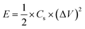
The FTIR spectra in Fig. 1 indicate the effect of metal–organic Co–Ti–EG glycolate on the synthesis of mesoporous CTO rods. There were a greater number of peaks observed for the as-synthesized Co–Ti–EG glycolate powder (Fig. 1(b)), which disappeared after annealing at a temperature of 600 °C (Fig. 1(a)). The peaks centered at 3328, 1452, 1050, and 876 cm−1 were assigned to the υOH, δOH, υCO, and γOH bands of the C–O and O–H bonds in the –CH2–OH moiety, respectively.19 In addition, the peaks centered at 2472, 1818, 1314, and 1210 cm−1 were assigned to the υOH, υC![[double bond, length as m-dash]](https://www.rsc.org/images/entities/char_e001.gif) O, δOH, and υCO bands of the CO, C–O, and O–H bonds in the –COOH group, respectively.19 The peaks centered at 2828 and 2923 cm−1 were indexed to the symmetric and anti-symmetric stretching vibrations, respectively, of the C–H bonds in the –CH2– group, instead of the –CH3 group.20 However, all of these peaks assigned to the various organic components might have decomposed into CO, CO2, and H2O, and disappeared after annealing the as-synthesized CTO powder at a temperature of 600 °C. Therefore, the presence of weak bands only between 400 to 800 cm−1 was assigned to the stretching vibrations of the metal ions of the mesoporous CTO rods (Fig. 1(a)).20
O, δOH, and υCO bands of the CO, C–O, and O–H bonds in the –COOH group, respectively.19 The peaks centered at 2828 and 2923 cm−1 were indexed to the symmetric and anti-symmetric stretching vibrations, respectively, of the C–H bonds in the –CH2– group, instead of the –CH3 group.20 However, all of these peaks assigned to the various organic components might have decomposed into CO, CO2, and H2O, and disappeared after annealing the as-synthesized CTO powder at a temperature of 600 °C. Therefore, the presence of weak bands only between 400 to 800 cm−1 was assigned to the stretching vibrations of the metal ions of the mesoporous CTO rods (Fig. 1(a)).20
 |
| | Fig. 1 FTIR spectra of (a) CTO microrod obtained after annealing (b) as-prepared Co–Ti–EG polymer chain precursor. | |
Fig. 2(a) shows the X-ray diffraction pattern of the annealed CTO microrod. The hexagonal crystal structure of the space group R (with the lattice parameters a = b = 5.0654, c = 13.9209 Å; α = β = 90° and γ = 120° (JCPDS: 72-1069)) was assigned to the mesoporous CTO microrods. The diffraction peaks identified at 2θ = 32.8, 35.4, 40.5, 49.08, 53.5, 56.9, 61.9, 63.6, 70.9, 74.9, and 77.1° were indexed as the (104), (210), (213), (024), (116), (018), (314), (030), (1010), (420), and (036) lattice planes, respectively. The well indexing of all diffraction peaks confirmed the formation of pure crystalline mesoporous CTO microrods without impurity phases, such as TiO2 and Co3O4. Furthermore, the Raman spectroscopic analysis shown in Fig. 2(b) was executed to understand the structural properties of the CTO rods. A total of 8 significant Raman bands observed at 691, 448, 375, 328, 257, 225, 204, and 156 cm−1 were consistent with the earlier reported values for CTO nanoparticles and micro-prisms.19,21 The strongest Raman mode observed at 691 cm−1 was assigned to the high frequency vibrational mode of the CoO6 octahedra known as the symmetry stretching mode, and the other remaining Raman modes were assigned to the lattice vibrations of the phonon modes.19,21 The observed Raman spectrum confirmed the absence of the other additional bands corresponding to Co3O4, TiO2, and the D/G bonds of carbon. Thus, the consistency of the Raman spectra with the XRD analysis also confirmed the formation of the pristine CTO rods.
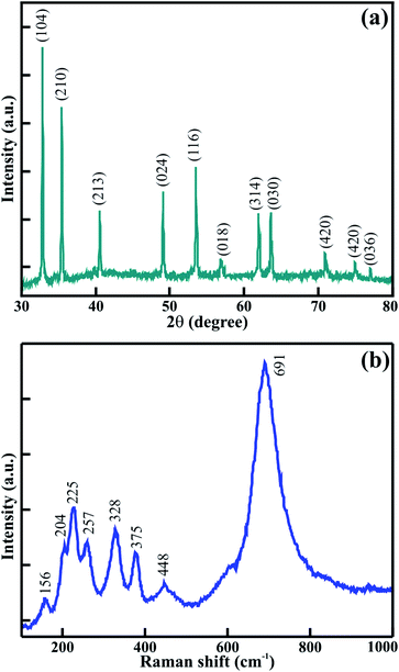 |
| | Fig. 2 (a) XRD pattern and (b) Raman spectrum of mesoporous CTO microrods. | |
The surface morphology was examined using FESEM to understand the effect of EG on the growth of the mesoporous CTO microrods. Fig. 3(a) shows the surface morphology of the as-synthesized CTO rods. The hexagonal shaped rods with a smooth surface and clearly visible textural boundaries were composed of Co–Ti–EG glycolate chains, and grown to the average diameter of ∼1.1 μm. These rods of Co–Ti–EG chains were further subjected to annealing at 600 °C. The smooth surface converted into the particle-like appearance without altering the hexagonal morphology of the rods (Fig. 3(b)). Co–Ti–EG glycolate was converted into intact CTO nanoparticles after the selective removal of EG glycolate on annealing. The well crystalline CTO nanoparticles were interconnected with adjacent nanoparticles, while maintaining the hexagonal morphological feature of the as-synthesized samples (Fig. 3(c)). The CTO nanoparticles of the average diameter of 40.7 (±0.5) nm resulted in mesoporous rods of the average diameter of 0.67 (±0.2) μm. Moreover, the formation of CTO nanoparticles that culminated in the mesoporous rods might be the result of the evaporation of the glycolate precursors.
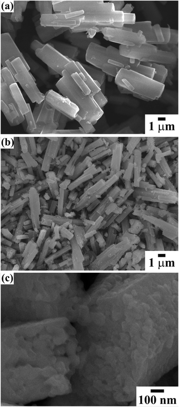 |
| | Fig. 3 FESEM image of (a) as-synthesized and (b) annealed CoTiO3 microrod. (c) The high-magnification FESEM image confirms the formation of mesoporous CoTiO3 microrod composed of hierarchically interlinked nanoparticles. | |
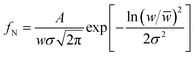
A statistical histogram of the width distribution of the hexagonal rods and nanoparticle diameter is shown in Fig. 3(a) and (b), respectively. It shows that all of the nanoparticles and rods were smaller than 70 nm and 1.2 μm, but most of them fell in the range of 30 to 50 nm and 0.6 to 0.75 μm, respectively. The variation of the widths could be fitted by the log-normal distribution function:22,23
| |
 | (1) |
where
w is the width of the nanoparticles and rods,
![[w with combining macron]](https://www.rsc.org/images/entities/i_char_0077_0304.gif)
is the mean width of the nanoparticles (≡40.7 ± 0.5 nm) and rods (≡0.67 ± 0.02 nm),
A is the initial constant for the nanoparticles (≡5.56 ± 0.59) and rods, and
σ is the standard deviation of the width distribution of the nanoparticles (≡0.18 ± 0.02) and rods (≡0.24 ± 0.02). The log-normal distribution of the width was asymmetrical for both CTO nanoparticles and rods. The small standard deviation of the width distribution (
σ ≤ 0.25) illustrates that the CTO nanoparticles and rods were well confined to the limited width range. Furthermore, energy dispersive spectroscopy (EDS) measurements were performed on annealed CTO samples to confirm the removal of the EG precursor at a temperature of 600 °C. The EDS spectra in
Fig. 4(c) confirms the presence of the elements Co, Ti, and O, only, which further confirms the high purity of the CTO samples.
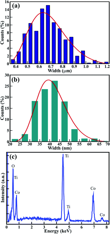 |
| | Fig. 4 (a and b) Statistical histogram of the width distribution microrods and nanoparticles, respectively, and (c) EDS spectra of mesoporous CTO microrods. | |
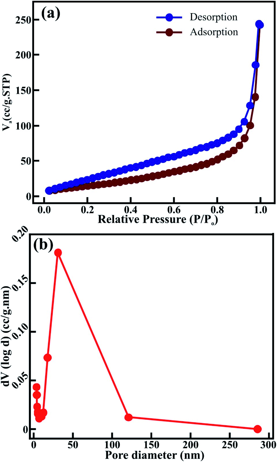
Nitrogen adsorption–desorption isotherm measurements for the sol–gel synthesized CTO microrod shown in Fig. 5 were performed to evaluate the pore structure. The distinctive hysteresis loop was mainly observed at higher pressures, i.e., 0.0–1.0 P/P0, indicating a type IV isotherm for the CTO microrod (Fig. 5(a)) and revealing a mesoporous structure. The pore volume and specific surface area of the CTO microrods measured from the N2 adsorption–desorption isotherm using the Brunauer–Emmett–Teller (BET) method were 0.142 cm3 g−1 and 126.89 m2 g−1, respectively. The higher surface area of the CTO microrods was attributed to the mesoporous hexagonal structure obtained after the linkage of the distinct CTO nanoparticles. Furthermore, the pore size distribution was analyzed as a function of the pore diameter for the CTO shown in Fig. 5(b) from the desorption curve using the Barrett–Joyner–Halenda (BJH) method. The broad peak of the pore size distribution curve confirmed the presence of a wide range of pores throughout the hexagonal CTO rods. A specific surface area and total pore volume of 126.89 m2 g−1 and 0.142 cm3 g−1, respectively, were observed for the hexagonal rods composed of CTO nanoparticles. The pore size distribution was confined to the range of 4 to 285 nm, with an average (mean) pore diameter distribution of 3.919 nm. Even though the largest pore diameter distribution of 285.3 nm was observed, most of the pores were in the range of 4–100 nm. The maximum number of pores had a diameter of 30.6 nm. The mesoporous CTO rods offered a larger surface area, and provided plenty of accessible sites deep inside the rod morphology for the collection of ions. Hence, it was expected to increase the interaction at the electrode–electrolyte interface. Moreover, the interconnection of the nanoparticles provided easy transportation for the ions to penetrate deep inside the mesoporous structure, and further assisted the significant improvement in the faradaic charge storage mechanism.
 |
| | Fig. 5 (a) N2 adsorption–desorption isotherm, and (b) BJH pore size distribution of the mesoporous CTO microrod. | |
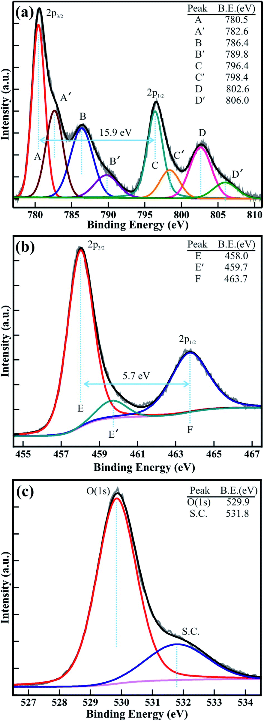
X-ray photoelectron spectroscopy (XPS) studies were carried out for the quantitative analysis of the electronic structure and chemical properties of the mesoporous CTO microrod. Fig. 6 shows the high-resolution XPS spectra of the core-levels of Co(2p), Ti(2p), and O(1s). The dual-peak feature of Co(2p) is shown in Fig. 6(a). The peaks corresponding to Co(2p3/2) and Co(2p1/2) were located at binding energies of 780.5 and 796.4 eV, respectively. The shake-up satellite peaks were observed at 786.4 and 802.6 eV, which are 5.9 and 6.2 eV higher in binding energy than that of the Co(2p3/2) and Co(2p1/2) peaks, respectively. The double peak feature of Co(2p) that was observed, along with the associated shake-up satellite peaks, reveals the paramagnetic chemical state of Co2+ and the open 3d9 shell of Co2+, and is usually observed in divalent magnetic elements like Cu and Ni.24 Furthermore, to precisely determine the double peak feature of Co(2p) and its shake-up satellite peak, the Co(2p) XPS spectra were decomposed via the Voigt curve fitting function, followed by a Shirley background. The Co(2p3/2) and Co(2p1/2) peaks were deconvoluted into four distinct peaks labeled as A, A′, C, and C′, and are located at binding energies of 780.5, 782.6, 796.4, and 798.4 eV. These four peaks (A, A′, C, and C′) represent the Co2+(2p3/2), Co3+(2p3/2), Co2+(2p1/2), and Co3+(2p1/2) peaks, respectively. The peak intensity of Co2+(2p3/2) was significantly (i.e., >2 times) larger than that of Co3+(2p3/2), indicating the presence of a substantially larger amount of Co2+ in the CTO. Moreover, the shake-up satellite peaks of Co(2p3/2) and Co(2p1/2) also decomposed into four discrete peaks identified as B, B′, D, and D′, and are located at the binding energies of 786.4, 789.8, 802.6, and 806.0 eV. B, B′, D, and D′ represent the shake-up satellite peaks of Co2+(2p3/2), Co3+(2p3/2), Co2+(2p1/2), and Co3+(2p1/2), respectively. The spin–orbit splittings between the Co(2p3/2) and Co(2p1/2) core levels and their shakeup satellite peaks were 15.9, and 16.2 eV, respectively, and is attributed to the presence of the larger amount of Co2+ than that of Co0 or Co3+ ions.15,25,26 Fig. 6(b) shows the XPS spectra of the Ti(2p) core levels, which were deconvoluted via Voigt curve fitting function within the Shirley background to precisely determine the double peak features of the Ti(2p3/2) and Ti(2p1/2) core levels. The decomposed peaks were observed at binding energies of 458.0 eV (i.e., E), 459.8 eV (i.e., E′), and 463.7 eV (i.e., F), and are assigned to the Ti4+(2p3/2), Ti3+(2p3/2) and Ti4+(2p1/2) core levels, respectively.3,5,27 The intensity of the Ti4+(2p3/2) was 12 times larger than that of Ti3+(2p3/2), confirming the presence of the larger amount of Ti4+ and only miniscule traces of Ti3+. This confirms that a very small quantity of Co3+ and Ti3+ is present in the CTO compound to achieve the stoichiometry. Furthermore, the O(1s) XPS spectra of the CTO microrod was decomposed via Voigt curve fitting function within the Shirley background (Fig. 6(c)), and show the perfect fits to two peaks located at 529.84 and 531.74 eV. This represents the O(1s) core level of the O2− anions and the surface contamination, such as carbon oxides or hydroxides5 in the mesoporous CTO rods. Moreover, the BE separation (ΔE) of 71.8 eV between O(1s) and Ti(2p3/2) was very close to the enthalpy of formation of CoTiO3.3 Overall, the XPS analysis confirms the formation of stable mesoporous CTO microrods consisting of a significantly larger amount of Co2+ and Ti4+ cations, and minor traces of Co3+ and Ti3+ cations.
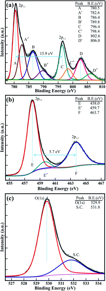 |
| | Fig. 6 Typical high-resolution XPS spectra of the (a) Co(2p), (b) Ti(2p), and (c) O(1s) core levels of the mesoporous CTO microrods. | |
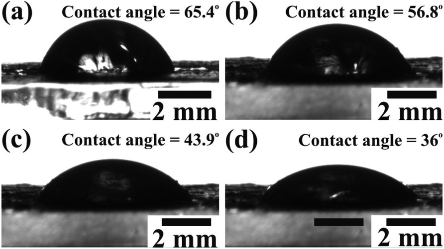
The diffusion of a large number of ions during the charging process is expected to gain the maximum value of Cs. Therefore, wettability studies were carried out to investigate the electrode–electrolyte interface mechanism. The average contact angle determined by the Young's relation for various concentrations of aqueous KOH electrolyte (0.5 M, 1 M, 1.5 M, and 2 M) on the electrode surface confirmed their inversely proportional relation. The contact angles of the CTO microrods measured for the 0.5 M (Fig. 7(a)), 1 M (Fig. 7(b)), 1.5 M (Fig. 7(c)), and 2 M (Fig. 7(d)) concentrations of aqueous KOH electrolyte were 65.4°, 56.8°, 43.9°, and 36°, respectively. The increase in the concentration of KOH electrolyte might have led to the improved cohesive force with the CTO microrods, and were expected to further enhance the diffusion of the electrolyte/ions deep inside the mesoporous CTO microrods. Therefore, the 2 M aq. KOH electrolyte exhibiting a lower contact angle with the CTO electrode was preferred for the electrochemical measurements.
 |
| | Fig. 7 Contact angle measurement showing the interface of the aqueous KOH electrolyte of (a) 0.5 M, (b) 1 M, (c) 1.5 M, and (d) 2 M concentration on the surface of the working electrode of mesoporous CTO microrods. | |
The electrochemical performance of the mesoporous CTO microrods was analyzed from cyclic voltammetry (CV), galvanostatic charge–discharge (GCD), and electrochemical impedance spectroscopy (EIS) in 2 M aq. KOH electrolyte. The CV was performed in the potential range of 0 to 0.6 V at different sweep rates, varying from 5, 10, 20, 40, 50, and 100 mV s−1 (Fig. 8(a)). The two distinct peaks observed at positive and negative current densities in the potential window of 0 to 0.6 V revealed the oxidation and reduction of the CTO rods, respectively. Furthermore, these oxidation and reduction peaks were shifted to relatively higher and lower potentials with an increase in the sweep rate. The oxidation peak observed for the potential of 0.36 V at a sweep rate of 5 mV s−1 shifted by 0.17 V (i.e., observed at 0.54 V) at the sweep rate of 100 mV s−1. Similarly, the reduction peak observed at 0.20 V for a sweep rate of 5 mV s−1 was shifted by 0.17 V (i.e., observed at 0.03 V) after increasing the sweep rate of 100 mV s−1. This shifting in the oxidation and reduction peaks with an increase in the sweep rate was assigned to the redox processes, owing to the polarization and ohmic resistance at the electrolyte–electrode interface during faradaic processes. This is akin to the observations for the Co3O4 hexagonal platelets composed of nanoparticle,28 Co3O4 nanorods,7 LaNiO3 nanotubes,29 and core–shell morphology of NiCo2O4 nanosheets and hollow microrod arrays.30 Moreover, the peak intensity and area under the CV graph have increased with an increase in the sweep rate, which is indicative of the more significant diffusion of OH− ions at the slower scan rates.
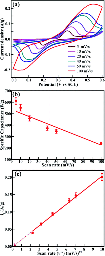 |
| | Fig. 8 (a) Cyclic voltammograms and (b) specific capacitance of mesoporous CTO microrod observed at various scan rates in 2 M aq. KOH electrolyte. (c) The graphical illustration of the anodic peak current density (ip) with the square root of the scan rate (ν1/2). | |
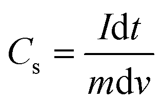
The specific capacitance (Cs) shown in Fig. 8(b) was evaluated from the CV graphs at various sweep rates (Fig. 8(a)) using the equation:
| |
 | (2) |
where
Cs is the specific capacitance (F g
−1),
m is the mass of the CTO microrods loaded in the working electrode (g),
ν is the scanning rate (mV s
−1), Δ
V is the applied potential range (V), and

is the integral area under the CV graph. The evaluated
Cs values linearly varied with the sweep rate. The
Cs value of 608.4 F g
−1 obtained at a sweep rate of 5 mV s
−1 was retained to 239.4 F g
−1 even after increasing the sweep rate to 100 mV s
−1. The easy access of the electrolyte deep inside the mesoporous CTO microrods might have provided a preeminent diffusion of the large number of OH
− ions at a slower sweep rate along the textural boundaries of the nanoparticles assembled in the mesoporous microrods, and further resulted in the larger
Cs value of 608.4 F g
−1. The increased sweep rate was expected to restrict the easy access of larger amounts of OH
− ions in a short time, and hence reduce the
Cs. The
Cs value of 608.4 F g
−1 conceived from the mesoporous CTO rods was relatively larger than those of the pristine Co
3O
4 and TiO
2 nanostructure morphologies, such as hexagonal platelet Co
3O
4 particles (
i.e., 476 F g
−1),
28 Co
3O
4 nanorods (
i.e., 351 F g
−1),
31 mesoporous Co
3O
4 nanosheets (
i.e., 92 F g
−1),
32 brookite TiO
2 nanoneedles (
i.e., 34.1 mF g
−1),
5 selectively dealloyed Ti/TiO
2 network nanostructures (
i.e., 35.5 F g
−1),
33 and NiO@Co
3O
4 core–shell nanofibers (
i.e., 437 F g
−1).
10 Moreover, the present mesoporous CTO microrods delivered significantly larger Cs values than the hetero-architectures of Co or Ti oxides formed with other compatible metal oxides or pristine/doped graphene oxides. A hierarchical 3D flower of Co
3O
4@MnO
2 grown on nitrogen-doped graphene oxide (NGO) hybrid composites delivered
Cs values of 347 F g
−1. Gobal
et al.34 synthesized NiO–ZnO/TiO
2 nanotubes, which were formed after calcination of the electrodeposited Zn–Ni over the TiO
2 nanotubes. These nanotubes provided Cs values of 325 F g
−1 in a 1 M NaOH electrolyte. The agglomeration of microwave-irradiated NTO nanoparticles restricted the easy access of the 0.5 M H
2SO
4 electrolyte, and hence constrained the redox process, further limiting the Cs value to 257 F g
−1.
17 Likewise, CTO provided a substantially higher Cs value than the other ABO
3 family members, such as LaFeO
3 (
i.e., 375.7 F g
−1),
35 LaNiO
3 (
i.e., 280 F g
−1),
29 and SrMnO
3 (
i.e., 321.7 F g
−1).
36 Furthermore, the variation of the current density with respect to the sweep rate was estimated by the Randle–Sevcik equation (
Fig. 8(c)):
| | |
ip = 2.69 × 10⁵Con3/2ν1/2D1/2
| (3) |
where
ip is the peak current density in mA g
−1,
Co is the concentration of OH
− ions in the electrolyte solution,
n is the number of electrons,
ν is the sweep rate in mV s
−1, and
D is the diffusion coefficient of the OH
− ions in the electrode material. The plot of the peak current density with respect to the sweep rate shows the linear behavior. The straight line passing through the origin confirms the diffusion-controlled adsorption and desorption of OH
− ions along the surface of the CTO nanoparticles assembling to form mesoporous microrods.
Fig. 9(a) shows the charge–discharge curves measured at various current densities, ranging from 30 to 120 mA g−1. The asymmetric behavior of the charge–discharge plots revealed the pseudocapacitive behavior of the mesoporous CTO microrods. Fig. 9(b) shows the specific capacitance (F g−1) at different current densities estimated from the equation:
| |
 | (4) |
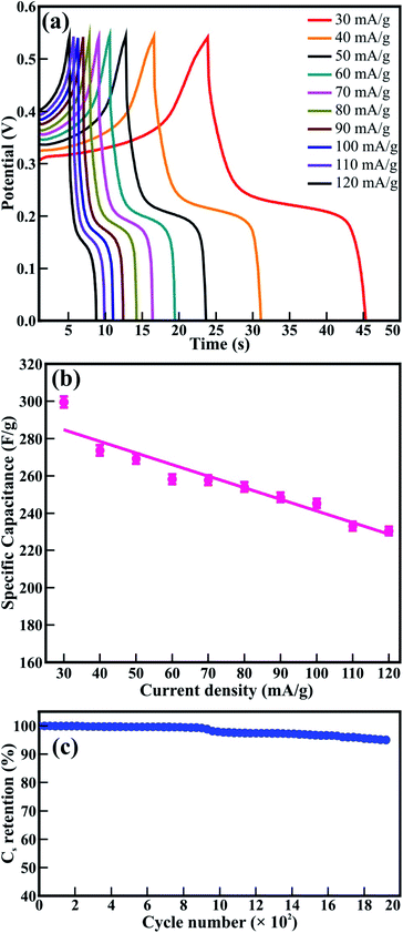 |
| | Fig. 9 (a) GCD curves and (b) evaluated specific capacitance of mesoporous CTO rods at various current densities. (c) Specific capacitance retention analyzed for 1950 GCD cycles at the current density of 100 mA g−1. The inset figure shows the first 10 cycles. | |
The maximum Cs of 299.5 F g−1 gained for the current density of 30 mA g−1 was reduced to 230.4 F g−1 at the current density to 120 mA g−1 (Fig. 9(b)). The time provided for the diffusion of ions deep inside the mesoporous microrods along the surface of the CTO nanoparticles was relatively small at the higher current density. That is why the Cs values were reduced with an increase in the current density. The Cs value of 299.5 F g−1 achieved from the mesoporous CTO microrods was significantly higher than the values reported for the other perovskites of di- and tri-valent metal ions, such as the PVP-assisted porous LaCoO3 nanospheres (i.e., 203 F g−1 in 6 M KOH),37 electrodeposited LaMnO3/MnO nanoarrays on carbon cloth (i.e., 260 F g−1 in 0.5 M Na2SO4),38 hydrothermally derived nanotube of Co@TiO2 and RGO composite (i.e., 27.5 F g−1),9 and sol–gel assisted Sr-doped LaMnO3 spheres (i.e., 198 F g−1).39 Moreover, the mesoporous CTO rods provided better Cs values than the nanocomposite prepared by varying the composition of the constituent phases of carbon, Fe2O3, and Co3O4. The Cs value of C/Fe2O3 (i.e., 85.3 F g−1) was further improved after the addition of Co3O4 (i.e., 144 F g−1).40 This reaffirmed that the CTO microrods were excellent electrode materials from the perovskite family in its pristine form.
The longer cyclic stability was essential for the better durable performance of the supercapacitor. Therefore, the cycling stability of the mesoporous CTO microrods was tested at a current density of 100 mA g−1 for 1950 charge–discharge cycles (Fig. 9(c)). The Cs values of 299.5 F g−1 were reduced by ∼2% for the initial 1000 cycles, which was further lowered by ∼5% after the 1950 continuous charge–discharge cycles. The observed capacitance retention for the mesoporous CTO microrods was more impressive than the values attained for the microwave-irradiated NTO nanoparticles17 and the electrodeposited LaMnO3/MnO nanoarrays.38 It was also compatible with the hierarchical flower-like 3D nanostructure of the Co3O4@MnO2/nitrogen-doped graphene oxide hybrid composite41 and the mesoporous perovskite of interlocked NiTiO3 nanoparticles.42 This distinct cyclic stability of the mesoporous CTO microrods confirms the better durability, longer lifetime, and excellent electrochemical stability in the 2 M KOH electrolyte.
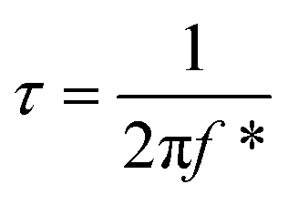
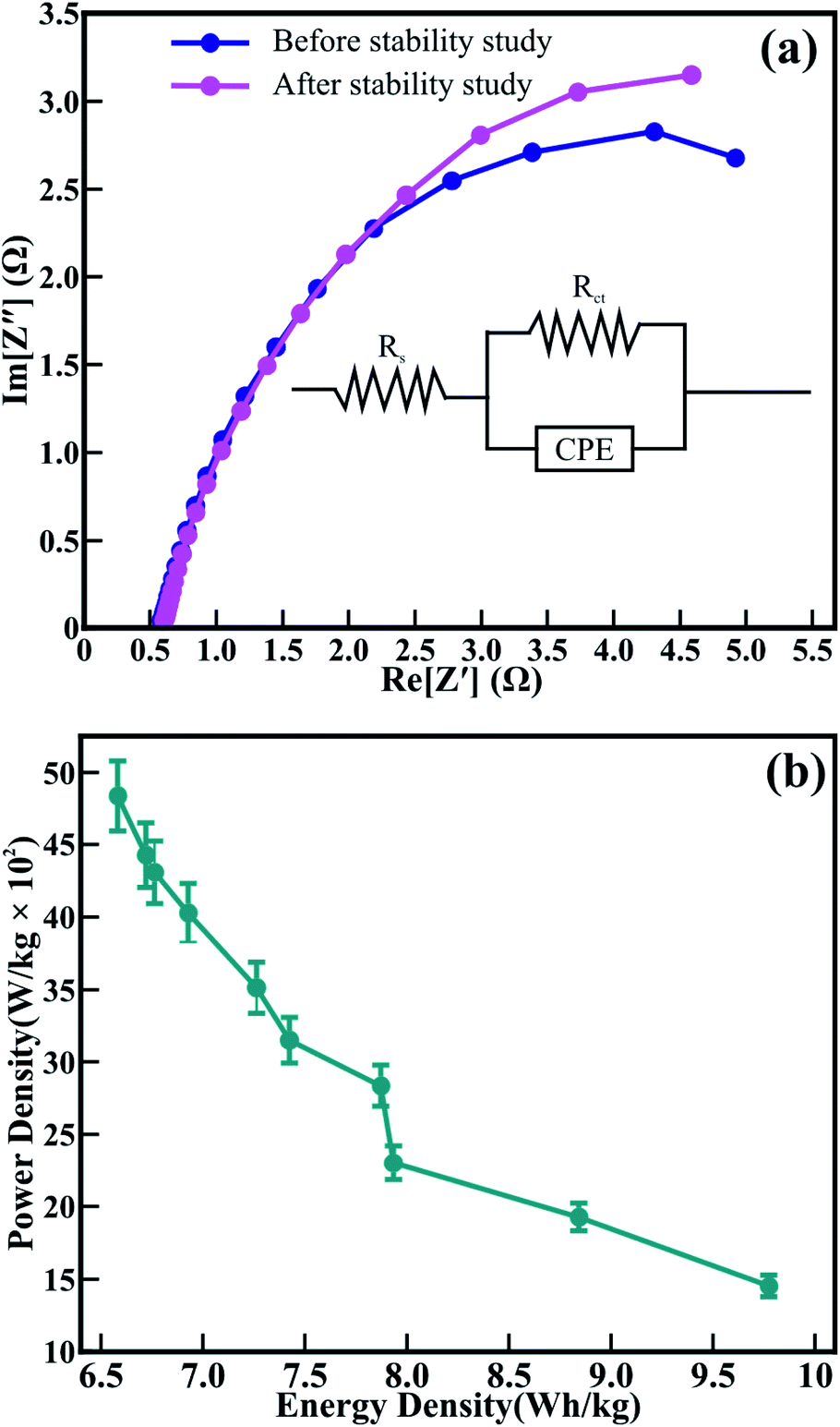
The surface morphology, textural boundaries, and electrical properties of the active electrode material play a vital role in the diffusion of the ions from the electrolyte. Therefore, electrochemical impedance spectroscopy (EIS) was employed to know the contribution of textural boundaries and electrical resistance in the diffusion of OH− ions in the mesoporous CTO microrods. Fig. 10(a) demonstrates the typical Nyquist plots of the CTO microrods in 2 M KOH electrolyte. The EIS spectrum of the mesoporous CTO microrods before the stability study is akin to that recorded after the stability study for 1950 charging–discharging cycles. The EIS spectra signify a perfect fit for the semicircular arc analogous to the charge-transfer resistance at the interface of the electrolyte and CTO microrods. This semicircular arc of the impedance spectra is similar to the Co3O4,7 TiO2,5 LaMnO3/MnO,38 and Sr-doped LaMnO3.39 The intercept and diameter of the semicircular arc symbolizing the charge transfer resistance (Rct) of 92.1 Ω for mesoporous CTO microrods has been reduced to 41.2 Ω after 1950 charge–discharge cycles. However, the values of the electrolyte resistance (Rs) obtained before the stability study (1.33 Ω) remained the same even after 1950 continuous charging–discharging cycles (1.37 Ω). The equivalent circuit for the EIS consists of the electrolyte resistance (Rs), charge transfer resistance (Rct), and constant phase elements denoted in the inset of Fig. 10(a). It confirms that the larger surface area, in conjunction with the clearly visible textural boundaries of the interconnected nanoparticles of the mesoporous CTO microrods, provides abundant access to the OH−-ions from the aq. KOH electrolyte. The partial drop in the charge diffusion of the mesoporous CTO microrods after 1950 cycles indicates the increase in the accessibility of the surface and textural boundaries of the mesoporous CTO rods during repeated charge–discharging cycles, which might be one of the reasons behind the excellent stability. The time constant was calculated to divulge the reaction kinetics for the transport of the OH− ions deep inside the CTO microrods from the equation:
| |
 | (5) |
where
f* is the frequency corresponding to the maxima of the imaginary component of the semicircle. The measured value of the time constant of 1.32 μs (before the stability study) confirmed the abrupt and easy access for the OH
−-ions to transport deep inside the CTO microrod along the textural boundaries. The time constant was not reduced even after 1950 charging–discharging cycles (
i.e., 1.59 μs), reinforcing the excellent cyclic stability observed for the mesoporous CTO microrods.
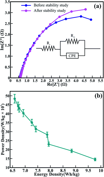 |
| | Fig. 10 (a) Nyquist (EIS) plot of the mesoporous CTO microrods obtained before and after cyclic stability studies. Inset shows the best fitted equivalent circuit model. (b) Evaluated specific energy and specific power of the mesoporous CTO microrods. | |
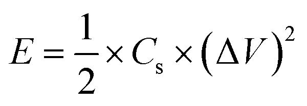
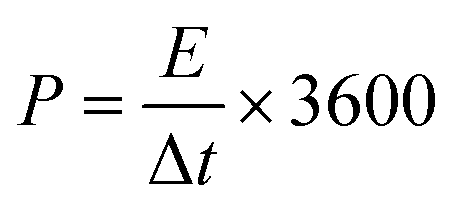
Fig. 10(b) exhibits the relation of the specific power and specific energy evaluated from eqn (6) and (7) to interpret the comprehensive performance of CTO,
| |
 | (6) |
| |
 | (7) |
where
Cs is the specific capacitance (F g
−1), Δ
V is the potential operating range (volts), Δ
t is the discharge time in (s),
P is the specific power (W kg
−1), and
E is the specific energy (W h kg
−1). The specific power reduces with respect to an enhancement in the specific energy, as the charge/discharge current density increased from 30 to 120 mA g
−1. The maximum specific power of 4835.7 W kg
−1 and a specific energy of 9.8 W h kg
−1 was obtained from mesoporous CTO. The specific power of 4835.7 W kg
−1 (at the current density of 30 mA g
−1) obtained for CTO was significantly higher than the hierarchical flower-like 3D nanostructure of the Co
3O
4@MnO
2/nitrogen-doped graphene oxide hybrid composite (
i.e., 850 W kg
−1),
41 3D TiO
2@Ni(OH)
2 core–shell nanowire arrays (
i.e., 1881.8 W kg
−1),
11 and 3D nanonet of hollow structured Co
3O
4 (
i.e., 100 W kg
−1).
43 Moreover, the performance of mesoporous CTO was relatively excellent in comparison with the perovskites of NiCo
2O
4 nanosheets@ hollow microrod arrays (
i.e., 100 W kg
−1),
30 Sr-doped LaMnO
3 nanoparticles (
i.e., 120 W kg
−1),
39 and 3D carbon-fiber network anchored with metallic Co (
i.e., 797 W kg
−1),
44 and was compatible with the mesoporous perovskite of interlocked NiTiO
3 nanoparticles (4320 W kg
−1).
42 The improved electrochemical performance of CTO is attributed to the well-connected network of CTO nanoparticles, well defined textural boundaries, and highly accessible larger surface area of the perforated mesoporous morphology, collectively furnishing the easy access for ion diffusion deep inside the mesoporous structure.
4 Conclusions
In conclusion, we report the synthesis of mesoporous cobalt titanite (CTO) microrods incorporating interconnected nanoparticles with clearly visible textural boundaries. The CTO nanoparticles of average diameter ∼59 nm were hierarchically organized in the hexagonal form, and provided mesoporous microrods of average diameter ∼800 nm and an average pore size distribution of 3.919 nm throughout the rod body. The CTO nanoparticles of the mesoporous rods are of the hexagonal crystalline phase to the space group of R. XPS analysis showed the consistent presence of Co2+/Co3+ and Ti4+/Ti3+, confirming the formation of stoichiometric CTO microrods. The interconnection of the CTO nanoparticles resulted in the formation of mesoporous CTO rods with increased textural boundaries, and offered a larger surface area for significantly larger diffusion of OH− ions. This further led to an increase in the Cs value in 2 M KOH electrolyte. The diffusion-controlled access to the OH− ions (0.27 μs) deep inside the rod structure provided a higher specific power (4835.7 W kg−1) and specific energy (9.77 W h kg−1) than the other perovskite family members. Moreover, the excellent stability for up to 1950 continuous charging–discharging cycles with the capacitance retention of 82.3% demonstrates that the mesoporous CTO microrods are a proficient working electrode for the supercapacitor. Furthermore, the morphology-dependent electrochemical performance shown in this study has unlocked a new corridor to explore the core–shell hetero-architectures of CTO rods with other metal oxides like TiO2, MnO2, and CuO as an electrode for hybrid capacitors, which may further enhance the electrochemical performance.
Conflicts of interest
There are no conflicts to declare.
Acknowledgements
The authors are thankful to the UGC-DAE CSR Indore for their financial support of this research under grant no. CSR-IC-BL-65/CRS-182/2017-18/189. The authors are also thankful to Dr Parasharam Shirage and Dr Santosh Hosmani, Discipline of MEMS, IIT Indore, for providing a research facility. N. R. K. acknowledges the Institute Fellowship from IIT Indore for Doctoral research work.
References
- K. Narasimharao, P. R. Chikate, R. A. Patil, Y. R. Ma, P. M. Shirage and R. S. Devan, CrystEngComm, 2019, 21, 7130–7140 RSC.
- C. Duan, J. Tong, M. Shang, S. Nikodemski, M. Sanders, S. Ricote, A. Almansoori and R. O' Hayre, Science, 2015, 349, 1321–1326 CrossRef CAS PubMed.
- K. Narasimharao, R. S. Kalubarme, P. R. Chikate, C. J. Park, Y. R. Ma, P. M. Shirage and R. S. Devan, ChemistrySelect, 2019, 4, 6620–6626 CrossRef.
- R. S. Devan, R. A. Patil, J. H. Lin and Y. R. Ma, Adv. Funct. Mater., 2012, 22, 3326–3370 CrossRef CAS.
- R. S. Devan, Y. R. Ma, R. A. Patil and S. M. Lukas, RSC Adv., 2016, 6, 62218–62225 RSC.
- X. Lu, G. Wang, T. Zhai, M. Yu, J. Gan, Y. Tong and Y. Li, Nano Lett., 2012, 12, 1690–1696 CrossRef CAS PubMed.
- T. Jiang, S. Yang, Z. Bai, P. Dai, X. Yu, M. Wu and H. Hu, Nanotechnol, 2018, 29, 315402 CrossRef PubMed.
- T. Arun, T. K. Kumar, R. Udayabhaskar, R. V. Mangalaraja and A. A. Fakhrabadi, Mater. Res. Express, 2019, 6, 0850b1 CrossRef CAS.
- H. Xiao, W. Guo, B. Sun, M. Pei and G. Zhou, Electrochim. Acta, 2016, 190, 104–117 CrossRef CAS.
- P. Jiang, Q. Wang, J. Dai, W. Li and Z. Wei, Mater. Lett., 2017, 188, 69–72 CrossRef CAS.
- Q. Ke, M. Zheng, H. Liu, C. Guan, L. Mao and J. Wang, Sci. Rep., 2015, 5, 13940 CrossRef PubMed.
- M. DiDomenico Jr. and S. H. Wemple, Phys. Rev., 1968, 166, 565 CrossRef.
- F. Hu, H. Zhang, C. Sun, C. Yin, B. Lv, C. Zhang, W. W. Yu, X. Wang, Y. Zhang and M. Xiao, ACS Nano, 2015, 9, 12410–12416 CrossRef CAS PubMed.
- M. Mizumaki, K. Yoshii, Y. Hinatsu, Y. Doi and T. Uruga, Phys. Scr., T, 2005, 115, 513–515 CrossRef.
- M. Shilpy, M. A. Ehsan, T. H. Ali, S. B. A. Hamid and M. E. Ali, RSC Adv., 2015, 5, 79644–79653 RSC.
- C. N. R. Rao, P. Ganguly, K. K. Singh and R. A. M. Ram, J. Solid State Chem., 1988, 72, 14–23 CrossRef CAS.
- M. Imani, L. Radmanesh and A. Tadjarodi, Ceram. Int., 2019, 45, 18772–18777 CrossRef CAS.
- P. Kakvand, M. S. Rahmanifar, M. F. El-Kady, A. Pendashteh, M. L. Kiani, M. Hashami, M. Najafi, A. Abbasi, M. F. Mousavi and R. B. Kaner, Nanotechnol, 2016, 27, 315401 CrossRef PubMed.
- Z.-D. Huang, T.-T. Zhang, H. Lu, J. Yang, L. Bai, Y. Chen, X.-S. Yang, R.-Q. Liu, X.-J. Lin, Y. Li, P. Li, X. Liu, X.-M. Feng and Y.-W. Ma, Sci. China Mater., 2018, 61, 1057–1066 CrossRef CAS.
- Y.-J. Lin, Y.-H. Chang, W.-D. Yang and B.-S. Tsai, J. Non-Cryst. Solids, 2006, 352, 789–794 CrossRef CAS.
- G.-W. Zhou, D. K. Lee, Y. H. Kim, C. W. Kim and Y. S. Kang, Bull. Korean Chem. Soc., 2006, 27, 368–372 CrossRef CAS.
- P. R. Chikate, K. D. Daware, S. S. Patil, P. N. Didwal, G. S. Lole, R. J. Chaudhary, S. W. Gosavi and R. S. Devan, New J. Chem., 2020, 44, 5535–5544 RSC.
- R. S. Devan, W. D. Ho, S. Y. Wu and Y. R. Ma, J. Appl. Crystallogr., 2010, 43, 498–503 CrossRef CAS.
- J. S. Shaikh, R. C. Pawar, R. S. Devan, Y. R. Ma, P. P. Salvi, S. S. Kolekar and P. S. Patil, Electrochim. Acta, 2011, 56, 2127–2134 CrossRef CAS.
- J. Anirudha, P. T. Rao, N. Munichandraiah and S. A. Shivashankar, J. Electroanal. Chem., 2016, 761, 21–27 CrossRef.
- G. Yang, W. Yan, J. Wang and H. Yang, Mater. Lett., 2014, 122, 117–120 CrossRef CAS.
- R. S. Devan, Y. R. Ma, M. A. More, R. T. Khare, V. V. Antad, R. A. Patil, V. P. Thakare, R. S. Dhayal and L. S. Mende, RSC Adv., 2016, 6, 98722–98729 RSC.
- K. Deori, S. K. Ujjain, R. K. Sharma and S. Deka, ACS Appl. Mater. Interfaces, 2013, 5, 10665–10672 CrossRef CAS PubMed.
- K. H. Ho and J. Wang, J. Am. Ceram. Soc., 2017, 100, 4629–4637 CrossRef CAS.
- X.-F. Lu, D.-J. Wu, R.-Z. Li, Q. Li, S.-H. Ye, Y.-X. Tong and G.-R. Li, J. Mater. Chem. A, 2014, 2, 4706–4713 RSC.
- F. Manteghi, S. H. Kazemi, M. Peyvandipour and A. Asghari, RSC Adv., 2015, 5, 76458–76463 RSC.
- S. Xiong, C. Yuan, X. Zhang, B. Xi and Y. Qian, Chem.–Eur. J., 2009, 15, 5320–5326 CrossRef CAS PubMed.
- P.-C. Chen, S.-J. Hsieh, J. Jou and C.-C. Chen, Mater. Lett., 2014, 133, 175–178 CrossRef CAS.
- F. Gobal and M. Faraji, Electrochim. Acta, 2013, 100, 133–139 CrossRef CAS.
- Z. Li, W. Zhang, C. Yuan and Y. Su, RSC Adv., 2017, 7, 12931–12937 RSC.
- G. George, S. L. Jackson, C. Q. Luo, D. Fang, D. Luo, D. Hu, J. Wen and Z. Luo, Ceram. Int., 2018, 44, 21982–21992 CrossRef CAS.
- Y. Guo, T. Shao, H. You, S. Li, C. Li and L. Zhang, Int. J. Electrochem. Sci., 2017, 12, 7121–7127 CrossRef CAS.
- P. Ma, N. Lei, B. Yu, Y. Liu, G. Jiang, J. Dai, S. Li and Q. Lu, Nanomater, 2019, 9, 1676 CrossRef CAS PubMed.
- X. W. Wang, Q. Q. Zhu, X. E. Wang, H. C. Zhang, J. J. Zhang and L. F. Wang, J. Alloys Compd., 2016, 675, 195–200 CrossRef CAS.
- J. Su, S. Liu, J. Wang, C. Liu, Y. Li and D. Wu, MRS Commun., 2016, 6, 367–374 CrossRef CAS.
- S. Ramesh, K. Karuppasamy, H.-S. Kim, H. Kim and J.-H. Kim, Sci. Rep., 2018, 8, 1–11 CrossRef CAS PubMed.
- N. Kitchamsetti, Y. R. Ma, P. M. Shirage and R. S. Devan, J. Alloys Compd., 2020, 833, 155134 CrossRef CAS.
- Y. Wang, Y. Lei, J. Li, L. Gu, H. Yuan and D. Xiao, ACS Appl. Mater. Interfaces, 2014, 6, 6739–6747 CrossRef CAS PubMed.
- A. P. Tiwari, S. H. Chae, G. P. Ojha, B. Dahal, T. Mukhiya, M. Lee, K. Chhetri, T. Kim and H. Y. Kim, J. Colloid Interface Sci., 2019, 553, 622–630 CrossRef CAS PubMed.
|
| This journal is © The Royal Society of Chemistry 2020 |
Click here to see how this site uses Cookies. View our privacy policy here. 
 Open Access Article
 This Open Access Article is licensed under a Creative Commons Attribution-Non Commercial 3.0 Unported Licence
 b,
Deodatta M. Phase
b,
Deodatta M. Phase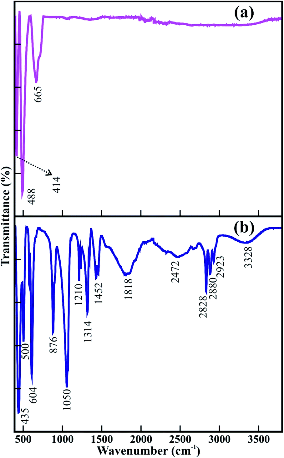


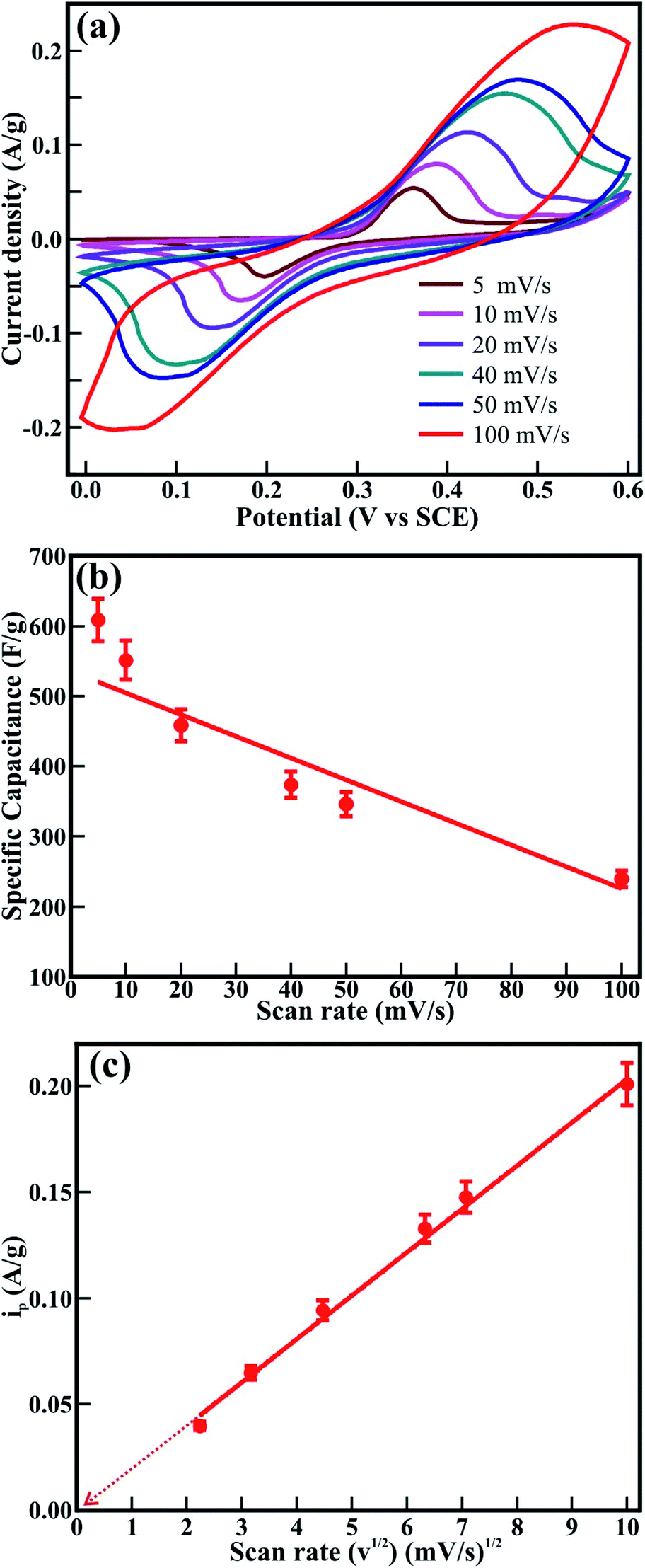
 is the integral area under the CV graph. The evaluated Cs values linearly varied with the sweep rate. The Cs value of 608.4 F g−1 obtained at a sweep rate of 5 mV s−1 was retained to 239.4 F g−1 even after increasing the sweep rate to 100 mV s−1. The easy access of the electrolyte deep inside the mesoporous CTO microrods might have provided a preeminent diffusion of the large number of OH− ions at a slower sweep rate along the textural boundaries of the nanoparticles assembled in the mesoporous microrods, and further resulted in the larger Cs value of 608.4 F g−1. The increased sweep rate was expected to restrict the easy access of larger amounts of OH− ions in a short time, and hence reduce the Cs. The Cs value of 608.4 F g−1 conceived from the mesoporous CTO rods was relatively larger than those of the pristine Co3O4 and TiO2 nanostructure morphologies, such as hexagonal platelet Co3O4 particles (i.e., 476 F g−1),28 Co3O4 nanorods (i.e., 351 F g−1),31 mesoporous Co3O4 nanosheets (i.e., 92 F g−1),32 brookite TiO2 nanoneedles (i.e., 34.1 mF g−1),5 selectively dealloyed Ti/TiO2 network nanostructures (i.e., 35.5 F g−1),33 and NiO@Co3O4 core–shell nanofibers (i.e., 437 F g−1).10 Moreover, the present mesoporous CTO microrods delivered significantly larger Cs values than the hetero-architectures of Co or Ti oxides formed with other compatible metal oxides or pristine/doped graphene oxides. A hierarchical 3D flower of Co3O4@MnO2 grown on nitrogen-doped graphene oxide (NGO) hybrid composites delivered Cs values of 347 F g−1. Gobal et al.34 synthesized NiO–ZnO/TiO2 nanotubes, which were formed after calcination of the electrodeposited Zn–Ni over the TiO2 nanotubes. These nanotubes provided Cs values of 325 F g−1 in a 1 M NaOH electrolyte. The agglomeration of microwave-irradiated NTO nanoparticles restricted the easy access of the 0.5 M H2SO4 electrolyte, and hence constrained the redox process, further limiting the Cs value to 257 F g−1.17 Likewise, CTO provided a substantially higher Cs value than the other ABO3 family members, such as LaFeO3 (i.e., 375.7 F g−1),35 LaNiO3 (i.e., 280 F g−1),29 and SrMnO3 (i.e., 321.7 F g−1).36 Furthermore, the variation of the current density with respect to the sweep rate was estimated by the Randle–Sevcik equation (Fig. 8(c)):