
 Open Access Article
 This Open Access Article is licensed under a Creative Commons Attribution-Non Commercial 3.0 Unported Licence
Selective CO2 reduction to HCOOH on a Pt/In2O3/g-C3N4 multifunctional visible-photocatalyst†
Jiehong He,
Pin Lv ,
Jian Zhu* and
Hexing Li*
,
Jian Zhu* and
Hexing Li*
Education Ministry Key and International Joint Lab of Resource Chemistry, Shanghai Key Laboratory of Rare Earth Functional Materials, Department of Chemistry, Shanghai Normal University, Shanghai 200234, China. E-mail: hexing-li@shnu.edu.cn; jianzhu@shnu.edu.cn; Fax: +86 21 64322272; Tel: +86 21 64322272
First published on 11th June 2020
Abstract
Selective photocatalytic reduction of CO2 has been regarded as one of the most amazing ways for re-using CO2. However, its application is still limited by the low CO2 conversion efficiency. This work developed a novel Pt/In2O3/g-C3N4 multifunctional catalyst, which exhibited high activity and selectivity to HCOOH during photocatalytic CO2 reduction under visible light irradiation owing to the synergistic effect between photocatalyst, thermocatalyst, and heterojunctions. Both In2O3 and g-C3N4 acted as visible photocatalysts, in which porous g-C3N4 facilitated H2 production from water splitting while the In2O3 nanosheets embedded in g-C3N4 pores favored CO2 fixation and H adsorption onto the Lewis acid sites. Besides, the In2O3/g-C3N4 heterojunctions could efficiently inhibit the photoelectron–hole recombination, leading to enhanced quantum efficiency. The Pt could act as a co-catalyst in H2 production from photocatalytic water splitting and also accelerated electron transfer to inhibit electron–hole recombination and generated a plasma effect. More importantly, the Pt could activate H atoms and CO2 molecules toward the formation of HCOOH. At normal pressure and room temperature, the TON of HCOOH in CO2 conversion was 63.1 μmol g−1 h−1 and could reach up to 736.3 μmol g−1 h−1 at 40 atm.
1. Introduction
CO2 conversion has attracted increasing interest owing to the consideration to both reduce the green-house effect and recycle carbon resources. The key problem is the CO2 fixation and activation steps, which play a critical role in determining the activity and selectivity.1,2 Previously, CO2 reduction was mainly driven by metal thermocatalysts,3–6 but it was usually performed at high temperature due to the highly stable CO2 molecule. Electrocatalytic CO2 reduction has also been reported, but additional energy is needed and the special reactor limits large scale-production.5,6 Photocatalytic CO2 reduction represents a promising way for CO2 conversion due to it being an energy saving and green process, which uses mild conditions, and has long durability.7–10 However, the photocatalytic efficiency is still very low because of the poor CO2 adsorption/activation ability and the easy photoelectron–hole recombination.11,12 Moreover, such a reaction usually displays low selectivity with the formation of various products like methane, methanol, formaldehyde, formic acid, etc. TiO2 has been frequently employed as in photocatalysis owing to its environmental friendship, easy availability, high activity, and excellent stability.13 However, TiO2 can only be activated by UV lights due to its large bandgap (3.2 eV) and thus cannot sufficiently make use of sunlight.14 In addition, the radical reaction steps disfavor the selectivity toward the target product. In2O3 can be activated by visible light and also can easily adsorb/activate CO2 molecules via Lewis acid sites, which greatly benefits the photocatalytic CO2 reduction toward HCOOH.15,16 But, pure In2O3 exhibits poor activity to generate H atoms through photocatalytic water splitting. The g-C3N4 is a typical visible photocatalyst for efficient water splitting,17 but could effectively adsorb and activate CO2 molecules. In addition, both In2O3 and g-C3N4 exhibit low activities due to the rapid combination between photoelectrons and holes.18 Construction of heterojunction structures is frequently used in designing photocatalysts with the low photoelectron–hole recombination rate and the high photocatalytic activity in pollutant-degradation, water splitting, and CO2 reduction.19,20 Many efforts have been devoted to improving the photocatalytic CO2 reduction efficiency.21–24 Obviously, the combination of In2O3 and g-C3N4 could mainly overcome their individual shortcomings in photocatalytic CO2 reduction. More importantly, the In2O3 displays energy level matching well with the g-C3N4. Thus, In2O3/g-C3N4 heterojunctions can be easily established, which can promote the photoelectron–hole separation to diminish photoelectron–hole recombination, leading to the high quantum efficiency in photocatalysis, which has applied into H2 evolution, CO2 reduction and pollutants degradation. Cao et al. reported an In2O3/g-C3N4 with enhanced activity in photocatalytic H2 evolution and CO2 reduction owing to the heterojunctions between g-C3N4 and In2O3, which promoted the transfer of photo-generated electrons and thus decreased the photoelectron–hole recombination.25 Non-noble metal like B and S has also been induced in In2O3/g-C3N4 to promote photocatalytic efficiency.26,27 Besides, noble metals like Pt and Pd have been widely applied in catalytic CO2 reduction with high activity and selectivity.28,29 Meanwhile, they could also be used as co-catalysts in photocatalysis to facilitate electron transfer owing to the excellent electric conductivity30,31 and to activate reactant molecules owing to the low work function.32Herein, we reported for the first time a Pt/In2O3/g-C3N4 nanocomposite and used as a multifunctional catalyst in photocatalytic CO2 reduction under visible light irradiation. The In2O3/g-C3N4 was prepared via a solvothermal route, while Pt was loaded through a photo-reduced method. The unique structural assemble and the strong interaction between nanoparticle Pt, nanosheet In2O3, and porous g-C3N4. As a result, the Pt/In2O3/g-C3N4 exhibited high activity and selectivity to HCOOH owing to the synergetic effects. The CO2 conversion TON reached up to 736.3 μmol g−1 h−1 at 40 atm and the catalyst exhibited excellent durability, showing good potential in the practical application.
2. Experimental
2.1 Sample preparation
In2O3 was prepared through a hydrothermal method. In a typical run of synthesis, 6 mmol In(NO3)3 (Aladdin) was added into a 40 mL aqueous solution, followed by stirring for 10 min to get a clear solution. Then, 24 mmol urea (Aladdin) was added and the solution was continuously stirred for 2 h at room temperature. Subsequently, the solution was transferred into a 50 mL Teflon lined autoclave and was kept at 140 °C for 16 h. The obtained solid product was washed thoroughly by water and ethanol, followed by drying at 60 °C for 12 h. Finally, it was calcined at 450 °C for 2 h to improve the crystallization degree of In2O3 and remove impurities.g-C3N4 was prepared by calcination of melamine (Aladdin) in a special reactor at 500 °C for 2 h, followed by calcining at 520 °C for another 2 h until the formation of faint yellow powder.
For preparing In2O3/g-C3N4, a certain amount of g-C3N4 was dispersed into 20 mL aqueous solution containing a certain amount of urea and was stirred for 2 h at room temperature. Meanwhile, a certain amount of indium nitrate was added to another 20 mL aqueous solution and was stirred until transparent. Then, the solution containing In(NO3)3 was carefully added into the solution containing g-C3N4 and urea. After being stirred for 2 h, the mixed solution was transferred into a 50 mL Teflon lined autoclave and kept at 140 °C for 16 h. The obtained solid product was washed by water and ethanol, followed by drying at 60 °C for 12 h, and finally, calcining at 450 °C for 2 h in argon atmosphere. The as-received sample was donated as xINCN, where x refers to the theoretical mass ratio of In2O3 to g-C3N4, which is adjusted by the added amount of g-C3N4 in mother solution. For comparison, the mechanical mixture of In2O3 and g-C3N4 was also prepared and was designated as INCN-mix.
The Pt-deposited photocatalysts were prepared by photoreduction of Pt ions. Briefly, 100 mg xINCN was dispersed in 10 mL ultra-pure water containing the desired amount of chloroplatinic acid and 1 mL TEOA (Aladdin). Then, the solution was irradiated with LED lamps for 30 min. After separation, the solid product was washed thoroughly with H2O and ethyl alcohol, followed by drying at 60 °C for 8 h. The as-received sample was marked as yPt–xINCN, where y is theoretical mass ratio of Pt to xINCN.
2.2 Characterization
The real contents of different components in composites were determined by using Inductive Coupled Plasma Emission Spectrometer (ICP, a Jarrel-Asm Atom Scan 2000). The N2 adsorption–desorption isotherms were obtained at 77 K using a Micromeritics ASAP 2010 instrument in which the specific surface area (SBET) and pore volume (VP) were calculated by applying Brunauer–Emmett–Teller (BET) and Barrett–Joyner–Halenda (BJH) models. X-ray diffraction (XRD) patterns were recorded on a Bruker D8 Advance X-ray diffractometer with Cu-Kα radiation at a scan rate of 0.02° s−1. The morphologies were measured on a field emission scanning electronic micrograph (FESEM, JEOL JSM-6380LV) and transmission electronic micrograph (TEM, JEM-2010). Energy-dispersive X-ray spectroscopy (EDS) was also performed by the JSM. The surface electronic states were investigated by X-ray photoelectron spectroscopy (XPS; ULVAC-PHI PHI5000 VersaProbe using Al Kα radiation). UV-Vis diffuse reflection spectra (DRS) were obtained on a Shimadzu UV-2450 Spectrophotometer using BaSO4 as a reference. The steady-state photoluminescence (PL) spectra were obtained by a Varian Cary-Eclipse 500 fluorometer at an excitation wavelength of 350 nm. Photocurrents were measured using an electrochemical analyzer (CHI660D Instruments) containing a standard three-electrode system in 0.5 M Na2SO4 aqueous solution as the electrolyte. The as-prepared sample was used as a working electrode with an active area of 20 × 20 mm2. The sample was prepared by traditional technology. First, 2 mg PVDF was added into 2 mL DMF solution under ultrasonic condition. Then, 20 mg catalyst was added. The suspension was obtained and treated by ultrasound for another 5 min, followed by dropping onto a FTO piece (20 × 20 mm2), vacuum drying at 80 °C for 8 h, and calcination at 150 °C for 1 h. A Pt piece with an area of 20 × 20 mm2 was used as a counter electrode and a saturated calomel electrode was used as a reference electrode. Each run of the measurements was performed by irradiating with a 300 W Xe lamp for 30 s at an interval of 30 s. Electrochemical impedance spectra (EIS) were obtained under the open-circuit potential condition, with an amplitude of 10 mV and frequency span from 10 kHz to 0.01 Hz.2.3 Activity test
The photocatalytic CO2 reduction was performed in a self-made 50 mL quartz reactor. Before reaction, 20 mg catalyst was dispersed in 10 mL ultra-pure water under ultrasonication for 30 min. Then, 1 mL TEOA (Aladdin) was introduced as a sacrificial agent. The suspension was transferred onto a 50 mL quartz reactor with two vents. High purity CO2 (99.99%) was introduced into the reactor and bubbled for 0.5 h to evacuate the air inside the reactor. Then, the reactor was sealed and filled with CO2 to 1 atm. For each run of reactions, the reaction system was irradiated for 4 h by four 3 W LED lights with the wavelength of 420 nm at a constant temperature of 35 °C and stirring rate of 800 rpm. The gas products were analyzed by a gas chromatography equipped by HP-PLOT Q column connected with the FID detector and TDX-01 connected with TCD detector. The liquid products were detected by ion chromatography (Dionex DX-320) with an analytical column (Dionex IonPac AS19-4 μm Analytical Column).3. Results and discussion
3.1 Structural characteristics
As shown in Fig. 1, the XRD patterns revealed that all the samples were present in well crystalline states of In2O3 and g-C3N4. The pure g-C3N4 displayed two peaks around 13.1° and 27.4° characteristic of (100) and (002) facets. The In2O3 was present in cubic structure (JCPDS card no. 06-0416) with the characteristic peaks at 30°, 35°, 51°, and 60°, corresponding (111), (100), (110), (622) facets, respectively. All the Pt/In2O3/g-C3N4 showed typical peaks indicative of individual In2O3 and g-C3N4, indicating no chemical bonding formed between In2O3 and g-C3N4. No significant diffraction peaks indicative of Pt were observed in Pt/In2O3, Pt/g-C3N4, or Pt–INCN owing to the low Pt-loading with high dispersion of Pt nanoparticles.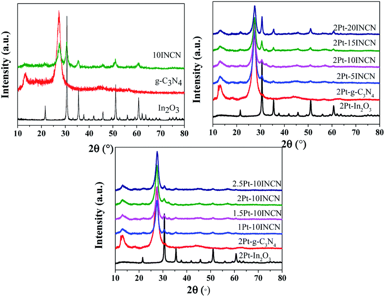 | ||
| Fig. 1 XRD patterns of pure In2O3, pure g-C3N4 and their corresponding composites with or without Pt-loading. | ||
The SEM and TEM images in Fig. 2 demonstrated that the In2O3 was present in nanosheets with an average length of 1–2 μm and widths of 50–100 nm, while the g-C3N4 was present in a lamina structure with uniform porous structure. The 10INCN composite displayed well dispersion of In2O3 nanosheets onto the g-C3N4. From 2Pt–10INCN, we could see very tiny Pt nanoparticles uniformly distributed onto the In2O3/g-C3N4 support. Interestingly, most of Pt nanoparticles were deposited onto the In2O3 nanosheets. This could be easily understood since Pt ions would be more easily reduced on the In2O3 than on the g-C3N4 owing to the presence of Lewis acid sites which favored the adsorption of PtCl62− ions. The HRTEM image further confirmed that the Pt nanoparticles were embedded on the interface between In2O3 and g-C3N4 in 2Pt–10INCN. Both In2O3 and g-C3N4 were present in well-defined crystals, in good accordance with the XRD patterns. The heterojunction was formed between In2O3 and g-C3N4. The mapping images clarified the existence of In2O3 and g-C3N4 in 2Pt–10INCN, together with the uniform distribution of Pt nanoparticles.
 | ||
| Fig. 2 SEM images of (a) In2O3, (b) g-C3N4 and (c) 10INCN. TEM images of (d) g-C3N4, (e) In2O3, (f) 10INCN, and (g) 2Pt–10INCN. (h) HRTEM image of 2Pt–10INCN. (i) Mapping images of 2Pt–10INCN. | ||
The actual In2O3-contents and Pt-loading in the composite photocatalysts were determined by ICP and expressed in mass percentage (Table S1†), which generally matched with the theoretical contents in the mother solution. All samples displayed type-IV N2 adsorption–desorption isotherms with a hysteresis loop of type H3 characteristic of porous structure (Fig. S1†). Based on the N2 adsorption–desorption isotherms, the surface area, pore size, and pore volume were calculated (Table S2†). Although the similar pore volume, the In2O3 exhibited higher surface area and bigger pore size than the g-C3N4 owing to the porous structure constructed layer-by-layer from In2O3 nanosheets. The INCN exhibited decreased surface area and pore size due to the incorporation of In2O3 nanosheets into the porous g-C3N4, leading to the close package of In2O3 nanosheets. The pore volume of INCN greatly increased in comparison with both In2O3 and g-C3N4, possibly owing to the formation of new micropores during the co-assembling process of In2O3 and g-C3N4. All the Pt–INCN displayed lower surface area and larger pore size as well as smaller pore volume, suggesting most Pt nanoparticles were embedded into the pore channels constructed layer-by-layer from In2O3 nanosheets. Some micropores were blocked by those Pt nanoparticles, which could account for the increase of average pore size and abrupt decrease of pore volume.
The XPS spectra in Fig. 3 revealed that all the In species were present in In3+ state, corresponding to the binding energies (BE) of 445.8 eV and 453.4 eV at In 3d5/2 and 3d3/2 levels.33 The negative BE shift suggested the strong interaction between In2O3 and g-C3N4, in which partial electrons transferred from g-C3N4 to In3+ due to the d–π feedback. Meanwhile, all the Pt species on In2O3, g-C3N4, and xINCN exhibited two principal peaks around BE of 71.4 eV and 74.5 eV in Pt 4f7/2 and Pt 4f5/2 energy levels (also see Fig. S2†), indicating they were all present in the metallic state.34 The Pt/In2O3 displayed negative BE shift of Pt and positive BE shift of In3+, which further confirmed that most Pt nanoparticles deposited onto In2O3 nanosheets, in which partial electrons transferred from In3+ to Pt owing to the strong metal–support interaction, taking into account of the higher electronegativity of Pt (2.28) than that of In3+ (1.78).32 All the O species were present in O2− state. The peak at 531.4 eV was assigned to lattice-oxygen and the peak at 532.5 eV was ascribed to chemisorbed oxygen.35 After Pt-loading, the BE of lattice-oxygen showed a negative shift owing to the acceptance of partial electrons from metallic Pt. Besides, the well-dispersed Pt nanoparticles on the In2O3 surface promoted the chemisorption of oxygen, leading to the enhanced intensity of the peak around 532.5 eV.36 The C species in 10INCN were mainly presented in C–N–C coordination, corresponding to the BE at 288.2 eV in C 1s level. The weak shoulder peak at 284.5 eV was ascribed to the sp2 C–C bond.37 The N species displayed various states, corresponding to the different binding energies in the N 1s level. The main signal around 398.6 eV corresponded to the N in C–N–C bond, while the shoulder peak at 400.3 eV was ascribed to the N in the N–(C)3 group.38 No significant BE shift of either the C or the N was observed, possibly due to the symmetric structure in C–N–C bond.
 | ||
| Fig. 3 XPS spectra in (a) C 1s, (b) N 1s, (c) O 1s and (d) In 3d and (e) Pt 4f levels. | ||
Due to the In2O3 and g-C3N4 are both indirect band semiconductors.39–42 It is reasonable that (αhν)0.5 vs. photon energy plot was used to estimate band-gap energy of them. From UV-Vis DRS spectra and their corresponding plots of (αhν)1/2 vs. photon energy (hν) (Fig. 4a and S3†), together with the calculated energy bandgaps and light absorbance edge wavelength (Table S3†), we could see that both In2O3 and g-C3N4 could be activated by visible lights. The 5INCN displayed a broader adsorption area with an obvious red-shift in comparison with the pure In2O3 and g-C3N4, which could be understood by considering the appearance of some intermediate energy bands owing to the formation of heterojunctions between In2O3 and g-C3N4. Further increase in the ratio of In2O3 to g-C3N4 (from 5INCN to 20INCN) had no significant influence on the light absorbance edge, suggesting no more heterojunctions formed. Meanwhile, both Pt/In2O3 and Pt/g-C3N4 exhibited red-shift comparing to pure In2O3 and g-C3N4, obviously owing to plasma effect from Pt nanoparticles, which could also account for the red-shift of light absorbance by loading Pt onto INCN. However, the change of Pt-loading from 1 wt% to 2 wt% had a very limited effect on the light adsorption edge, suggesting the similar size of Pt nanoparticles, and thus, the increased Pt-loading could only enhance the light adsorption intensity. However, 2.5Pt–10INCN displayed a blue-shift of light absorbance wavelength due to the gathering of Pt nanoparticles, which reduced the plasma effect. All the increasing ratio of In2O3 to g-C3N4 had almost on effect on the light absorbance wavelength in INCN, it caused remarkable red-shift in 2Pt–xINCN. This could be ascribed to the enhanced plasma effect from Pt nanoparticles at high-content In2O3 since the above TEM images demonstrated that the Pt ions were preferentially reduced and deposited onto In2O3 rather than g-C3N4.
 | ||
| Fig. 4 (a) UV-Vis DRS spectra and their corresponding plots of (αhν)1/2 vs. photon energy, (b) steady-state PL spectra at λex of 350 nm, (c) electrochemical impedances, and (d) photocurrent response spectra obtained under irradiation of a 300 W Xe lamp. | ||
The steady-state PL spectra obtained at an excited wavelength of 350 nm (Fig. 4b and S4†) displayed an emission peak around 450 nm indicative of the recombination between photoelectrons and holes. The 10INCN exhibited lower intensity compared to In2O3 and g-C3N4, implying the lowest photoelectron–hole combination rate, which could be attributed to the rapid charge transfer through the In2O3–C3N4 heterojunctions. With the increase of the In2O3/C3N4 ratio up to 10INCN, the PL peak intensity decreased gradually owing to the formation of more In2O3–C3N4 heterojunctions, corresponding to the reduced photoelectron–hole combination rate. However, further increase in the In2O3/C3N4 ratio resulted in the increasing PL peak intensity due to the presentence of more free In2O3 nanosheets, leading to the enhanced photoelectron–hole combination rate. Loading Pt could greatly decrease the PL peak intensity, corresponding to the efficient inhibition of photoelectron–hole combination, obviously owing to the rapid electron transfer through Pt nanoparticles to separate from holes. The 2Pt–10INCN showed the lowest photoelectron–hole combination rate. This could be further by the electrochemical impedance spectra (Fig. 4c and S5†). The loading of Pt nanoparticles onto In2O3, C3N4, and INCN resulted in a significant decrease of arc radius, corresponding to the reduced electric resistance owing to the excellent electric conductivity of metallic Pt. The 2Pt–10INCN displayed the smallest arc radius, corresponding to the lowest electric resistance. Further increase in the Pt-loading caused an enlarged arc radius corresponding to the enhanced electric resistance, which could attribute to the gathering of Pt nanoparticles.
The photocurrent response spectra (Fig. 4d and S6†) clearly demonstrated that the INCN exhibited higher photocurrent than either the pure In2O3 or the pure g-C3N4, which could attribute to the enhanced light absorbance and decreased photoelectron–hole recombination rate as discussed above. Increasing the In2O3/g-C3N4 ratio from 5 to 10 wt% resulted in the enhanced photocurrent intensity. A possible reason was the rapid electron transfer from g-C3N4 to In2O3 since In2O3 was present in well-defined crystals with better electric conductivity than g-C3N4 in poor crystallization, which might decrease the photoelectron–hole recombination. Further increasing the In2O3/g-C3N4 ratio to 15 wt% caused a decrease in photocurrent intensity due to the presence of more free In2O3 nanosheets. Those free In2O3 displayed higher photoelectron–hole recombination rate than the In2O3/g-C3N4 nanocomposite due to the absence of heterojunctions (Fig. S4a†).43 Meanwhile, the Pt–INCN showed a higher photocurrent than the INCN owing to the enhanced light absorbance and decreased photoelectron–hole recombination rate as discussed above. The highest photocurrent was observed on the 2Pt–10INCN, corresponding to the highest light absorbance and the lowest photoelectron–hole recombination rate.
3.2 Catalytic performances
Controlled experiments (Fig. S7†) demonstrated that only trace HCOOH and CH4 obtained during CO2 reduction on 2Pt–10INCN without light irradiation or CO2, suggesting the CO2 reduction was mainly driven by photocatalysis. The addition of K2Cr2O7 as an electron capture agent resulted in an abrupt decrease in CO2 conversion efficiency, showing the photoelectrons played a key role in photocatalytic CO2 reduction. Meanwhile, it was also found that the HCOOH yield greatly decreased without adding TEOA in the reaction system. TEOA was frequently used as a hole capturing agent in photocatalysis,44 which could consume photo-induced holes from the photocatalyst through its oxidation (see Scheme S1†) and thus could inhibit their recombination with photoelectrons. Therefore, TEOA was a necessary sacrifice agent in the present photocatalytic CO2 reduction.Under UV light irradiation, the 2Pt–10INCN exhibited higher HCOOH and CH4 yields than that under visible light irradiation (Fig. S8a†) since the UV light could generate more photoelectrons and holes. Taking into account that the sunlight contained only less than 5% UV lights, we still employed the visible light irradiation for driving the photocatalysis to simulate the natural photosynthesis. The 2Pt–10INCN exhibited extremely high selectivity to HCOOH in photocatalytic CO2. Only very little CH4 could be obtained and no other side-products were detected. With the increase of reaction time to 4 h, the HCOOH yield increased rapidly and an only slight increase in CH4 yield was observed. However, further increase in the reaction time had no significant influence on the CO2 reduction efficiency (Fig. S8b†), indicating the reaction arrived equilibrium point. So, 4 h was used as the reaction time in the following activity tests. Meanwhile, the increase of CO2 pressure could also greatly promote photocatalytic CO2 reduction toward HCOOH (see Fig. S8c†). The HCOOH yield could reach up to 736.3 μmol g−1 h−1 at 4.0 MPa, which represented a high level in CO2 conversion in photosynthesis. However, the increasing CO2 pressure resulted in a rapid increase of the CH4 yield (see Fig. S8d†), the high cost, and the difficult operation. Thus, we employed the normal CO2 pressure (1 atm) in the following tests to meet the requirement of industrial production.
Fig. 5 demonstrated that both In2O3 and g-C3N4 could be activated by visible lights. Although the In2O3 contained sufficient Lewis acid sites to absorb CO2 molecules, it showed very low activity due to its high CB potential (−0.62 V vs. NHE) which could not efficiently generate H atoms by photocatalytic water splitting. The g-C3N4 was active to produce H atoms photocatalytic water splitting owing to its low CB potential (−1.1 V vs. NHE). However, its adsorption for CO2 molecules was very poor due to the lack of active sites together with the low surface area, leading to the poor activity of photocatalytic CO2 reduction. The INCN exhibited higher activity than either the In2O3 or g-C3N4 owing to the cooperation between In2O3 and g-C3N4 to adsorb CO2 molecules and produce H atoms. Meanwhile, the INCN contained narrow energy bandgap owing to the presence of intermediate energy bands and thus could be more easily and effectively activated by visible lights. More importantly, the INCN contained enriched heterojunctions between In2O3 and g-C3N4, which facilitated the electron transfer from the CB of g-C3N4 to that of In2O3, leading to the lower photoelectron–hole recombination rate. Although the pure In2O3 exhibited very poor activity in photocatalytic CO2 reduction, the Pt/In2O3 exhibited remarkable enhancement on the activity since the metallic Pt could act as a co-catalyst to produce H atoms by collecting electrons from In2O3 semiconductor and plasma during photocatalytic water splitting.45 More importantly, the Pt/In2O3 displayed much higher selectivity to HCOOH than the pure In2O3, which could be understood based on a plausible reaction pathway in photocatalytic CO2 reduction (Scheme S1†). The noble-metal Pt was a typical metal catalyst with low work function to activate H atoms while the In2O3 could efficiently adsorb CO2 molecules owing to the presence of enriched Lewis acid sites.46,47 The Lewis acid sites also enhanced the interaction between Pt and In2O3, which induced the unique bridged co-adsorption model of the CO2 molecule on Pt and In2O3. Such co-adsorbed CO2 molecules favored the reaction with active H atoms to HCOO*,48–50 which was a key intermediate in determining the selectivity to HCOOH.16 Besides, the metallic Pt nanoparticles also promoted the activation of In2O3 by visible lights owing to the plasma effect and facilitated the electron transfer to diminish photoelectron–hole recombination, which could further promote the photocatalytic CO2 reduction. Similarly, the Pt/g-C3N4 also exhibited higher activity and selectivity than the g-C3N4, which could also be explained based on the above discussions. It was noted that the Pt-loading exhibited much weaker promoting effect on the HCOOH production in g-C3N4 than that in In2O3. A possible reason was that the g-C3N4 could not effectively adsorb CO2 molecules due to the absence of Lewis acid sites. Although the presence of Pt could greatly enhance the production of H atoms, no enough adsorbed CO2 molecules could be activated and subsequently reacted with those H atoms. Meanwhile, the Pt/g-C3N4 displayed poor interaction between Pt and g-C3N4 due to the absence of Lewis acid sites, leading to the low number of bridge-co-adsorbed CO2 molecules on both Pt and g-C3N4, which could account for the lower selectivity to HCOOH in comparison with the Pt/In2O3.
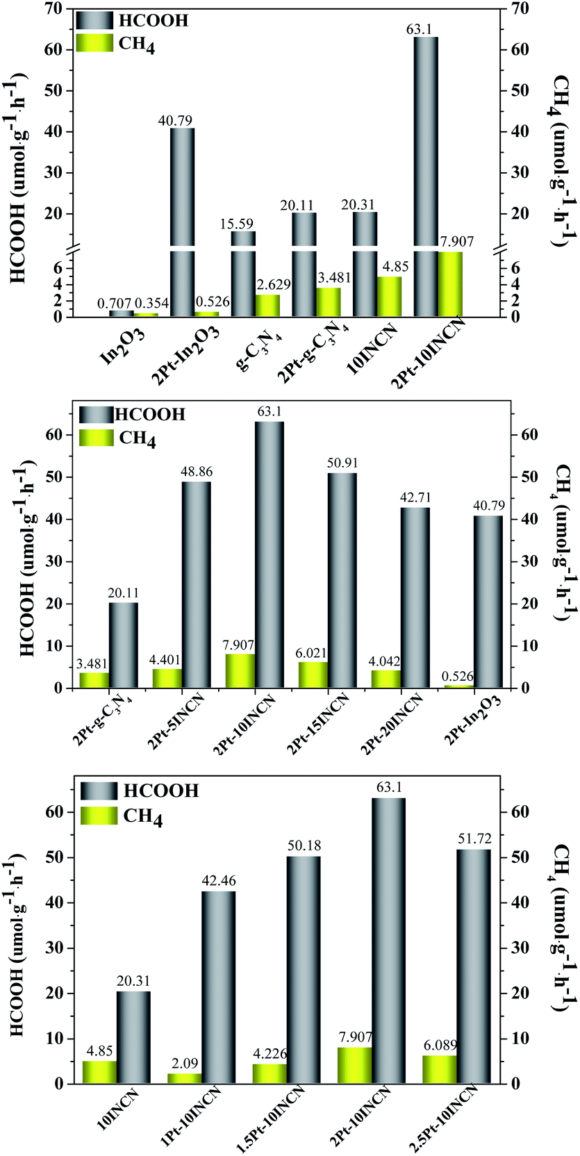 | ||
| Fig. 5 HCOOH and CH4 yields on different catalysts. Reaction conditions: Four 3 W LED (420 nm), 1 atm CO2, 20 mg catalyst, 10 mL H2O, 1 mL TEOA, 35 °C, 4 h. | ||
As expected, the Pt-loading onto INCN also greatly enhanced the activity and selectivity in photocatalytic CO2 reduction, which could also be accounted by considering various Pt-functions discussed above. Interestingly, the Pt–INCN exhibited a much stronger promoting effect than either the Pt/In2O3 or Pt/g-C3N4 possibly owing to the enhanced role of heterojunctions. The presence of metallic Pt nanoparticles facilitated electron-transfer from In2O3 to g-C3N4 and hole-transfer from g-C3N4 to In2O3, which could greatly diminish photoelectron–hole recombination (see Scheme S1†). By fixing the Pt-loading at 2 wt%, the Pt–INCN showed a rapid increase in HCOOH yield while only very slight increase in CH4 yield with the increasing ratio of In2O3/g-C3N4 up to 10 wt%. This could be ascribed to the enhanced adsorption of CO2 molecules by In2O3. Besides, the increase of heterojunctions played a key role in promoting the photocatalytic CO2 reduction by inhibiting photoelectron–hole recombination. However, further increase of the In2O3-content caused slight decrease in the HCOOH yield due to the appearance of free In2O3 nanosheets. Such a free In2O3 displayed higher photoelectron–hole recombination rate than the In2O3/g-C3N4 nanocomposite due to the absence of heterojunctions.51 In addition, since the In2O3 favored the photocatalytic reduction of PtCl62+, some of Pt nanoparticles would deposit onto the free In2O3 nanosheets, leading to the reduced promoting effect on the role of heterojunctions between In2O3 and g-C3N4.
By fixing the In2O3-content at 10 wt%, the Pt–10INCN exhibited increasing HCOOH yield and CH4 yield with the increase of Pt-loading up to 2 wt% since more Pt nanoparticles would enhance the plasma effect, the activity for activating H atoms and CO2 molecules, the electron transfer ability to inhibit photoelectron–hole recombination. However, further increase in the Pt-loading caused slight decrease in either the HCOOH yield or the CH4 yield due to the gathering of Pt nanoparticles to reduce above promoting effects. Besides, the large Pt nanoparticles may also block the pore channels, leading to an abrupt decrease in surface area (see Table S2†). The 2Pt–10INCN exhibited the highest HCOOH yield (63.1 μmol g−1 h−1) at the normal pressure of CO2 and room temperature. In addition, the 2Pt–10INCN exhibited much higher activity than the 2Pt–10INCN-mix obtained by mechanical mixing In2O3 and g-C3N4 (see Fig. S7†), obviously due to the absence of heterojunctions and the synergetic effect between In2O3 and g-C3N4.
The lifetime is also a key parameter to determine the practical application of a photocatalyst. As shown in Fig. 6, both 2Pt–10INCN and 2Pt–In2O3 could be used repetitively for more than 5 times without a significant decrease in their activities. The slight decrease might be caused by the loss of photocatalysts during separation and wash processes. However, the 2Pt–g-C3N4 showed a rapid decrease in photocatalytic activity during the recycling test. The XRD patterns (Fig. S9†) revealed that, similar to 2Pt–In2O3 and 2Pt–g-C3N4, no significant change in the structure of 2Pt–10INCN was observed, indicating the excellent stability during the reaction process. Meanwhile, ICP analysis demonstrated no significant Pt leaching occurred on either 2Pt–10INCN or 2Pt–In2O3 occurred during the reaction, which could be attributed to the strong adsorption of Pt nanoparticles onto In2O3 owing to the presence of Lewis acid sites. However, the 2Pt–g-C3N4 showed Pt leaching during the reaction process, leading to a decrease in photocatalytic activity.
 | ||
| Fig. 6 Recycling test of 2Pt–In2O3, 2Pt–g-C3N4 and 2Pt–10INCN. Reaction conditions are given in Fig. 5. | ||
4. Conclusions
We developed a Pt/In2O3/g-C3N4 multifunctional catalyst by controlling the assembling method. This catalyst exhibited high activity and selectivity to HCOOH during visible-light-driven photocatalytic CO2 reduction owing to the synergetic effects in producing H atoms via water splitting, adsorbing/activating CO2 molecules, and inhibiting photoelectron–hole recombination by accelerating electron transfer and forming heterojunctions. Besides, it also displayed a long lifetime owing to the high structural stability and the strong interaction to inhibit Pt leaching. This work supplied a promising way for designing new catalysts with multiple functions for photocatalytic CO2 reduction at normal pressure and room temperature with a high yield of target products.Conflicts of interest
There are no conflicts to declare.Acknowledgements
This work was supported by NSFC (21761142011, 51572174) and Shanghai Government (18JC1412900, 19YF1436600, 19160712900, 17SG44) as well as Shanghai Engineering Research Center of Green Energy Chemical Engineering.References
- K. Shimomaki, K. Murata, R. Martin and N. Iwasawa, J. Am. Chem. Soc., 2017, 139, 9467–9470 CrossRef CAS PubMed.
- S. Zhang, W.-Q. Chen, A. Yu and L.-N. He, ChemCatChem, 2015, 7, 3972–3977 CrossRef CAS.
- P. Riani, G. Garbarino, M. A. Lucchini, F. Canepa and G. Busca, J. Mol. Catal. A: Chem., 2014, 383–384, 10–16 CrossRef CAS.
- P. Zhu, Q. Chen, Y. Yoneyama and N. Tsubaki, RSC Adv., 2014, 4, 64617–64624 RSC.
- S. Zhang, P. Kang and T. J. Meyer, J. Am. Chem. Soc., 2014, 136, 1734–1737 CrossRef CAS PubMed.
- J. Shen, R. Kortlever, R. Kas, Y. Y. Birdja, O. Diaz-Morales, Y. Kwon, I. Ledezma-Yanez, K. J. P. Schouten, G. Mul and M. T. M. Koper, Nat. Commun., 2015, 6, 8177 CrossRef PubMed.
- B. A. Parkinson and P. F. Weaver, Nature, 1984, 309, 148–149 CrossRef CAS.
- L. Liu, C. Zhao and Y. Li, J. Phys. Chem. C, 2012, 116, 7904–7912 CrossRef CAS.
- Y. Liao, S. Cao, Y. Yuan, Q. Gu, Z. Zhang and C. Xue, Chem.–Eur. J., 2014, 20, 10220–10222 CrossRef CAS PubMed.
- W. Wang, W. An, B. Ramalingam, S. Mukherjee, D. M. Niedzwiedzki, S. Gangopadhyay and P. Biswas, J. Am. Chem. Soc., 2012, 134, 11276–11281 CrossRef CAS PubMed.
- Y. Ma, X. Wang, Y. Jia, X. Chen, H. Han and C. Li, Chem. Rev., 2014, 114, 9987–10043 CrossRef CAS PubMed.
- A. S. Hall, Y. Yoon, A. Wuttig and Y. Surendranath, J. Am. Chem. Soc., 2015, 137, 14834–14837 CrossRef CAS PubMed.
- Z. Bian, J. Zhu and H. Li, J. Photochem. Photobiol., C, 2016, 28, 72–86 CrossRef CAS.
- C. Dette, M. A. Perezosorio, C. S. Kley, P. Punke, C. E. Patrick, P. Jacobson, F. Giustino, S. J. Jung and K. Kern, Nano Lett., 2014, 14, 6533–6538 CrossRef CAS PubMed.
- M. Chen, J. Xu, Y. Cao, H. He, K. Fan and J. Zhuang, J. Catal., 2010, 272, 101–108 CrossRef CAS.
- J. Ye, C. Liu and Q. Ge, J. Phys. Chem. C, 2012, 116, 7817–7825 CrossRef CAS.
- J. Chen, S. Shen, P. Guo, M. Wang, P. Wu, X. Wang and L. Guo, Appl. Catal., B, 2014, 152, 335–341 CrossRef.
- Y. Wang, Y. Li, X. Bai, Q. Cai, C. Liu, Y. Zuo, S. Kang and L. Cui, Catal. Commun., 2016, 84, 179–182 CrossRef CAS.
- Y.-H. Chiu, M. T.-F. Chang, C.-Y. Chen, M. Sone and Y.-J. Hsu, Catalysts, 2019, 9, 430 CrossRef CAS.
- M.-J. Fang, C.-W. Tsao and Y.-J. Hsu, J. Phys. D: Appl. Phys., 2020, 53, 143001 CrossRef CAS.
- K. Wang, Q. Li, B. Liu, B. Cheng, W. Ho and J. Yu, Appl. Catal., B, 2015, 176, 44–52 Search PubMed.
- S. Cao, Y. Li, B. Zhu, M. Jaroniec and J. Yu, J. Catal., 2017, 349, 208–217 CrossRef CAS.
- T. Di, B. Zhu, C. Bei, J. Yu and J. Xu, J. Catal., 2017, 352, 532–541 CrossRef CAS.
- H. Guo, M. Chen, Q. Zhong, Y. Wang, W. Ma and J. Ding, J. CO2 Util., 2019, 33, 233–241 CrossRef CAS.
- S. Cao, X. Liu, Y. Yuan, Z. Zhang, Y. Liao, J. Fang, S. C. J. Loo, T. C. Sum and C. Xue, Appl. Catal., B, 2014, 147, 940–946 CrossRef CAS.
- X. Jin, Q. Guan, T. Tian, H. Li, Y. Han, F. Hao, Y. Cui, W. Li, Y. Zhu and Y. Zhang, Appl. Surf. Sci., 2020, 504, 144241 CrossRef.
- P. Zhou, X. Meng and T. Sun, Mater. Lett., 2020, 261, 127159 CrossRef CAS.
- K. Liu, M. Ma, L. Wu, M. Valenti, D. Cardenasmorcoso, J. P. Hofmann, J. Bisquert, S. Gimenez and W. A. Smith, ACS Appl. Mater. Interfaces, 2019, 11, 16546–16555 CrossRef CAS PubMed.
- Z. Yin, G. T. R. Palmore and S. Sun, Trends Chem., 2019, 1, 739–750 CrossRef.
- Z. Xiong, Z. Lei, C.-C. Kuang, X. Chen, B. Gong, Y. Zhao, J. Zhang, C. Zheng and J. C. S. Wu, Appl. Catal., B, 2017, 202, 695–703 CrossRef CAS.
- B. Cao, G. Li and H. Li, Appl. Catal., B, 2016, 194, 42–49 CrossRef CAS.
- Y. Wang, J. Zhao, Y. Li and C. Wang, Appl. Catal., B, 2018, 226, 544–553 CrossRef CAS.
- D. V. Shinde, V. V. Jadhav, D. Y. Lee, N. K. Shrestha, J. K. Lee, H. Y. Lee, R. S. Mane and S.-H. Han, J. Mater. Chem. A, 2014, 2, 5490–5498 RSC.
- J. Cheng, M. Zhang, G. Wu, X. Wang, J. Zhou and K. Cen, Environ. Sci. Technol., 2014, 48, 7076–7084 CrossRef CAS PubMed.
- A. Thomas, A. Fischer, F. Goettmann, M. Antonietti, J. O. Muller, R. Schlogl and J. M. Carlsson, J. Mater. Chem., 2008, 18, 4893–4908 RSC.
- Y. Liu, X. Gao, F. Li, G. Lu, T. Zhang and N. Barsan, Sens. Actuators, B, 2018, 260, 927–936 CrossRef CAS.
- K. Park, G. H. Gunasekar, N. Prakash, K. Jung and S. Yoon, Chemsuschem, 2015, 8, 3410–3413 CrossRef CAS PubMed.
- S. Wang, B. Y. Guan and X. W. D. Lou, J. Am. Chem. Soc., 2018, 140, 5037–5040 CrossRef CAS PubMed.
- Z. Li, P. Zhang, T. Shao and X. Li, Appl. Catal., B, 2012, 125, 350–357 CrossRef CAS.
- Z. Wang, B. Huang, Y. Dai, X. Qin, X. Zhang, P. Wang, H. Liu and J. Yu, J. Phys. Chem. C, 2009, 113, 4612–4617 CrossRef CAS.
- F.-J. Zhang, F.-Z. Xie, S.-F. Zhu, J. Liu, J. Zhang, S.-F. Mei and W. Zhao, Chem. Eng. J., 2013, 228, 435–441 CrossRef CAS.
- J. Liu, J. Alloys Compd., 2016, 672, 271–276 CrossRef CAS.
- Y.-F. Lin and Y.-J. Hsu, Appl. Catal., B, 2013, 130–131, 93–98 CrossRef CAS.
- S. Kumar, R. K. Yadav, K. Ram, A. Aguiar, J. Koh and A. J. F. N. Sobral, J. CO2 Util., 2018, 27, 107–114 CrossRef CAS.
- Y. Sui, S. Liu, T. Li, Q. Liu, T. Jiang, Y. Guo and J.-L. Luo, J. Catal., 2017, 353, 250–255 CrossRef CAS.
- N. Rui, Z. Wang, K. Sun, J. Ye, Q. Ge and C.-j. Liu, Appl. Catal., B, 2017, 218, 488–497 CrossRef CAS.
- J. Kim and J. Lee, J. Chem. Phys., 2000, 113, 2856–2865 CrossRef CAS.
- G. Gao, Y. Jiao, E. R. Waclawik and A. Du, J. Am. Chem. Soc., 2016, 138, 6292–6297 CrossRef CAS.
- D. G. Shchukin, S. K. Poznyak, A. I. Kulak and P. Pichat, J. Photochem. Photobiol., A, 2004, 162, 423–430 CrossRef CAS.
- M. Tasbihi, F. Fresno, U. Simon, I. J. Villar-García, V. Pérez-Dieste, C. Escudero and V. A. de la Peña O'Shea, Appl. Catal., B, 2018, 239, 68–76 CrossRef CAS.
- Y.-C. Chen, Y.-C. Pu and Y.-J. Hsu, J. Phys. Chem. C, 2012, 116, 2967–2975 CrossRef CAS.
Footnote |
| † Electronic supplementary information (ESI) available. See DOI: 10.1039/d0ra03959d |
| This journal is © The Royal Society of Chemistry 2020 |