 Open Access Article
Unexpected bowing band evolution in an all-inorganic CsSn1−xPbxBr3 perovskite†
Yufan Xia‡
a,
Yuxuan Chen‡ab,
Tian Luoa,
Hongyao Lianga,
Yujia Gaoa,
Xin Xua,
Weiguang Xie a,
Pengyi Liua,
Xin Wang
 b,
Yu-Jun Zhao
 *c and
Tingting Shi
 *a
*a
aSiyuan Laboratory, Guangzhou Key Laboratory of Vacuum Coating Technologies and New Energy Materials, Guangdong Provincial Engineering Technology Research Center of Vacuum Coating Technologies and New Energy Materials, Department of Physics, Jinan University, Guangzhou 510632, China. E-mail: ttshi@jnu.edu.cn
bNational Center for International Research on Green Optoelectronics, South China Normal University, Guangzhou 510006, China
cDepartment of Physics, South China University of Technology, Guangzhou, Guangdong 510640, China. E-mail: zhaoyj@scut.edu.cn
First published on 14th July 2020
Abstract
We theoretically investigated the structural and electronic properties of the all-inorganic perovskite CsSn1−xPbxBr3, compared with the mixed perovskite compound MAyCs1−ySn1−xPbxBr3, based on first-principle calculations. It has been demonstrated that Pb and Sn atoms are inclined to occupy the lattice sites uniformly in the all-inorganic perovskite, and this is distinguished from the most stable configurations observed in the mixed Cs-MA system. It is interesting that small Sn atoms prefer to stay close to the large MA+ cations, leading to smaller local structural distortion. Through spin-orbital coupling calculations, we found non-linear bowing band evolution in the all-inorganic mixed Sn–Pb system with a small bowing parameter (b = 0.35), while the band gap of MAyCs1−ySn1−xPbxBr3 was clearly reduced as the ratio of MA was around 0.5 (y ≥ 0.25). We determined the bowing band evolution in the mixed cation perovskites and the intrinsic electronic deficiency of the all-inorganic perovskite to obtain the optimal band gap.
Introduction
With the rapid development of photovoltaic materials, the power conversion efficiency (PCE) of perovskite solar cells has been swiftly improved to 25.2% within ten years,1–5 resulting in photovoltaic power generation systems being in the spotlight in the research field. However, thermal and light stabilities still need to be stressed in the process of commercialization. Therefore, all-inorganic perovskite solar cells without hydrophilic organic cations have attracted increasing attention due to their outstanding thermal stability and phase stability.6–11 Noticeably, the PCE of an all-inorganic perovskite obtained a rapid rise to 19.03%,12 which has been predicted to approach the highest PCE record for a hybrid organic perovskite. Moreover, all-inorganic perovskites can be focused, due to their significant potentials in optical communication, safety monitoring, and biological sensing, by tuning the element compositions for wide applications.13,14 All-inorganic perovskites consist of an ABX3 structure, where cation A is selected to be the inorganic cation (Cs+), atom B is a metal cation (Sn2+ or Pb2+) and X is a halogen anion (Cl−, Br− or I−). Recent theoretical and experimental reports have shown that compositional engineering is an efficient strategy to suitably change the optoelectronic properties in order to aim for specific functionalities.15,16 Considering the properties of photovoltaic materials, one important characteristic that a perovskite system should possess is the applicable band gap around the optimal value of 1.3–1.4 eV, according to the Shockley–Queisser (SQ) limitation.17 Unfortunately, inorganic perovskites, such as CsPbI3 and CsPbBr3, both have wider band gaps (Eg = 1.74 eV and 2.34 eV, respectively),9,18–20 implying that the maximum theoretical efficiency of these solar cells will be greatly restricted.Previously, the mixture of cations and metal atoms were used to realize a higher stability and more suitable electronic properties in hybrid organic–inorganic perovskite solar cells. In 2014, Kanatzidis's group experimentally found the anomalous band gap behavior in a mixed Sn and Pb perovskite.21 The energy band gaps of the mixed Pb–Sn perovskite following Vegard's law22 were observed to be as low as around 1.1 eV, when the ratio of Pb![[thin space (1/6-em)]](https://www.rsc.org/images/entities/char_2009.gif) :
:![[thin space (1/6-em)]](https://www.rsc.org/images/entities/char_2009.gif) Sn was close to 1
Sn was close to 1![[thin space (1/6-em)]](https://www.rsc.org/images/entities/char_2009.gif) :
:![[thin space (1/6-em)]](https://www.rsc.org/images/entities/char_2009.gif) 1, thus broadening the light absorption into the near-infrared region. Furthermore, the antagonism phenomenon between the spin–orbit coupling (SOC) and the steric effect was investigated theoretically in MASn1−xPbxI3 materials.23 The mixture of compositions can be applied to tune the electronic properties to enhance light absorption and PCE. In a recent experiment, Guo et al. reported a methodology for uniform Sn–Pb mixed perovskite films by a one-step blade coating method, yielding high efficiencies of over 15%.24 The compositional engineering of mixing cations can be used to flexibly tune the optoelectronic properties, and thus increase the PCE.
1, thus broadening the light absorption into the near-infrared region. Furthermore, the antagonism phenomenon between the spin–orbit coupling (SOC) and the steric effect was investigated theoretically in MASn1−xPbxI3 materials.23 The mixture of compositions can be applied to tune the electronic properties to enhance light absorption and PCE. In a recent experiment, Guo et al. reported a methodology for uniform Sn–Pb mixed perovskite films by a one-step blade coating method, yielding high efficiencies of over 15%.24 The compositional engineering of mixing cations can be used to flexibly tune the optoelectronic properties, and thus increase the PCE.
In this paper, we aim to theoretically reveal insight into the band gap bowing effect that is introduced by the mixing of Sn and Pb metal atoms in an all-inorganic perovskite. The structural and optoelectronic configurations of the all-inorganic CsSn1−xPbxBr3 and MAyCs1−ySn1−xPbxBr3 perovskites are systematically calculated based on density functional theory. We found that Pb and Sn atoms prefer to occupy dispersedly in the all-inorganic CsSn1−xPbxBr3 system, and this is different to in the mixed cation MAyCs1−ySn1−xPbxBr3 system. The obvious bowing band evolutions were found in the mixed perovskite system when SOC calculations were employed. Based on all the calculated band gap values, the fit curves showed a non-linear changing trend of the band gaps for each perovskite system, following Vegard's law. Intriguingly, the band gap cannot be significantly reduced in the all-inorganic Sn–Pb perovskite compounds, due to it having the smallest bowing parameter value, compared with the larger bowing parameter values in the MA–Cs mixed systems. Therefore, the deficiency of electronic properties in the all-inorganic perovskite is difficult to overcome through compositional engineering, unlike in the case of bowing band evolution in the hybrid organic perovskite materials.
Methods
In this study, all calculations were performed using the Vienna ab initio simulation package (VASP),25 based on density functional theory (DFT). The projector augmented wave (PAW)26 pseudopotentials were used within the Perdew–Burke–Ernzerhof (PBE) functional27,28 for the exchange–correlation functional. The plane-wave cutoff energy for the basis was set to 400 eV. A 2 × 2 × 2 supercell and a Monkhorst–Pack 3 × 3 × 3 k-point mesh in first Brillouin zone29 integrations were carried out within supercell calculations. Heyd–Scuseria–Ernzerhof (HSE03)30 and PBE0![[thin space (1/6-em)]](https://www.rsc.org/images/entities/char_2009.gif) 31 hybrid functionals were also employed for further calculations. Additionally, all structures were constructed in the cubic phase to save computational time. Four high-symmetric k-points were included for the band structures calculation: G (0, 0, 0), X (0, 1/2, 0), M (1/2, 1/2, 0), and R (1/2, 1/2, 1/2). The atomic positions were relaxed until the energy converged within 10−4 eV and the absolute values of the force on the atoms were less than 0.02 eV Å−1. Due to the involvement of the heavy metal Pb, the spin–orbit coupling (SOC)32,33 effect was considered in our calculations. It is of great importance to calculate the perovskite systems using GGA + SOC and PBE0 + SOC. Although the method of GGA + SOC underestimates the value of the bandgap,34 it presents the changing trend of the band evolution accurately. All crystal structures were constructed by VESTA.35
31 hybrid functionals were also employed for further calculations. Additionally, all structures were constructed in the cubic phase to save computational time. Four high-symmetric k-points were included for the band structures calculation: G (0, 0, 0), X (0, 1/2, 0), M (1/2, 1/2, 0), and R (1/2, 1/2, 1/2). The atomic positions were relaxed until the energy converged within 10−4 eV and the absolute values of the force on the atoms were less than 0.02 eV Å−1. Due to the involvement of the heavy metal Pb, the spin–orbit coupling (SOC)32,33 effect was considered in our calculations. It is of great importance to calculate the perovskite systems using GGA + SOC and PBE0 + SOC. Although the method of GGA + SOC underestimates the value of the bandgap,34 it presents the changing trend of the band evolution accurately. All crystal structures were constructed by VESTA.35
Results and discussion
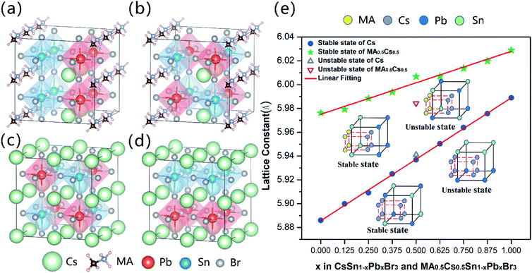
Fig. 1(a) and (b) show the most stable and metastable crystal structures of MA0.5Cs0.5Sn0.5Pb0.5Br3. After relaxation, the perovskite structure is distorted slightly when mixing MA and Cs, leading to a pseudo-cubic phase. The crystal structures of the most stable and the metastable CsSn0.5Pb0.5Br3 states are shown in Fig. 1(c) and (d) with the space group Pm![[3 with combining macron]](https://www.rsc.org/images/entities/char_0033_0304.gif) m. It is clear that the occupation sites of the Pb and Sn metal atoms in the most stable configurations are opposite for CsSn0.5Pb0.5Br3 and MA0.5Cs0.5Sn0.5Pb0.5Br3. In other words, the Pb and Sn metal atoms are occupied dispersedly in the most stable configuration of CsSn0.5Pb0.5Br3, while they are clustered together in the most stable configuration of the MA0.5Cs0.5Sn0.5Pb0.5Br3 system. Other stable mixed configurations are illustrated in Fig. S1 (ESI).† This interesting phenomenon is related to the larger size of the MA+ cations. Clearly, the small Sn atoms of the stable configurations of the MAyCs1−ySn1−xPbxBr3 (0 < y ≤ 0.5) compound tend to stay close to the MA+ cations to reduce the local structural distortion (as seen in Fig. S1 (ESI)†). As shown in Fig. 1(e), we further found that the lattice constants of the stable systems vary linearly with the increase of Pb2+ ion content, satisfying Vegard's law. Nevertheless, the lattice constants of the metastable systems deviate from the linear fitting line. In order to clarify the relative occupied sites of the metal atoms, we used a schematic diagram to elucidate the different atomic positions between the stable configurations and the metastable configurations (inset of Fig. 1(e)). Details of the lattice constants can be seen in Table S2 (ESI).†
m. It is clear that the occupation sites of the Pb and Sn metal atoms in the most stable configurations are opposite for CsSn0.5Pb0.5Br3 and MA0.5Cs0.5Sn0.5Pb0.5Br3. In other words, the Pb and Sn metal atoms are occupied dispersedly in the most stable configuration of CsSn0.5Pb0.5Br3, while they are clustered together in the most stable configuration of the MA0.5Cs0.5Sn0.5Pb0.5Br3 system. Other stable mixed configurations are illustrated in Fig. S1 (ESI).† This interesting phenomenon is related to the larger size of the MA+ cations. Clearly, the small Sn atoms of the stable configurations of the MAyCs1−ySn1−xPbxBr3 (0 < y ≤ 0.5) compound tend to stay close to the MA+ cations to reduce the local structural distortion (as seen in Fig. S1 (ESI)†). As shown in Fig. 1(e), we further found that the lattice constants of the stable systems vary linearly with the increase of Pb2+ ion content, satisfying Vegard's law. Nevertheless, the lattice constants of the metastable systems deviate from the linear fitting line. In order to clarify the relative occupied sites of the metal atoms, we used a schematic diagram to elucidate the different atomic positions between the stable configurations and the metastable configurations (inset of Fig. 1(e)). Details of the lattice constants can be seen in Table S2 (ESI).†
In addition, the Goldschmidt tolerance factor is a crucial index in predicting the stability of halide perovskites: , where r is the ionic radius.36,37 A tolerance factor of within 0.9–1.0 is an ideal stable cubic structure in perovskite materials. It is known that increasing the radius of A (rA) and decreasing the radius of B (rB) are important and effective strategies to improve the stability of perovskites. Hence, a larger cation (MA+) mixed with Cs+ and a smaller metal cation (Sn2+) alloyed with Pb2+ are necessary to investigate. The teff (Cs+ = 1.88 Å, Sn2+ = 1.12 Å, Pb2+ = 1.19 Å, and Br− = 1.96 Å)38 value of CsSnBr3 (0.882) is larger than that of CsPbBr3 (0.862), indicating that CsSnBr3 as the possible candidate is more stable for the photovoltaic application of inorganic perovskites.
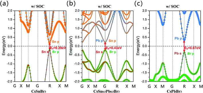
Subsequently, we calculated projected band structures of CsSnBr3, CsSn0.5Pb0.5Br3 and CsPbBr3, and these are displayed in Fig. 2(a)–(c), through GGA + SOC methods (w/SOC). The Sn-5s, Sn-5p, Pb-6s, Pb-6p and Br-4p orbitals are highlighted in red, orange, pink, blue and green, respectively. It can be clearly seen that the band gap calculated by GGA + SOC gradually increases with the addition of the Pb2+ cation and the projected band structure indicates that the Sn-5s, Pb-6s and Br-4p orbitals contribute most to the valence band maximum (VBM) state, and the conduction band minimum (CBM) state is dominated by the Sn-5p and Pb-6p orbitals. It is clear that the bandgap of CsSn0.5Pb0.5Br3 is not smaller than that of CsSnBr3.
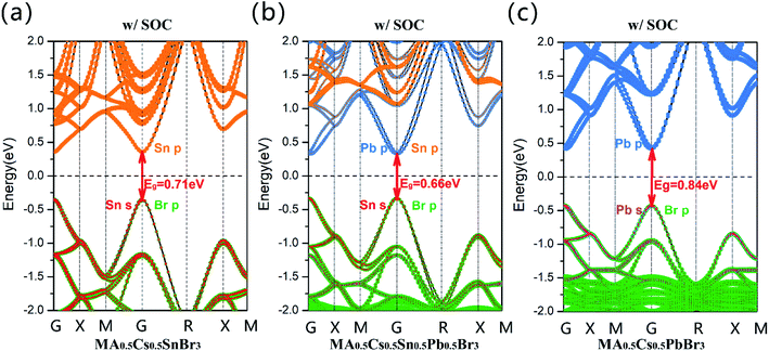
However, for the MA0.5Cs0.5Sn0.5Pb0.5Br3 system, its band gap (GGA + SOC: 0.66 eV) is clearly lower than that of the pure Sn and pure Pb configurations, as shown in Fig. 3(b). There is an anomalous band gap evolution after the addition of the MA+ ion. From the projected band structures, we found that both Sn-5p and Pb-6p orbitals contribute to the CBM in MA0.5Cs0.5Sn0.5Pb0.5Br3. Herein, the band gap in the MA0.5Cs0.5SnBr3 compound is 0.71 eV, as shown in Fig. 3(a), and the band gap in the MA0.5Cs0.5PbBr3 compound is 0.84 eV, as shown in Fig. 3(c).
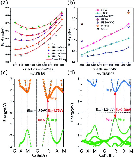
Considering the alloy of the Sn–Pb systems studied in our calculations, according to Vegard's law, we quantificationally fit the band bowing curves and obtained the corresponding bowing parameter b values. The band gap of mixing A and B atoms can be estimated using the relationship below:39–41
| Eg(A1−xBx) = (1 − x)Eg(A) + xEg(B) − bx(1 − x) | (1) |
| System | Fitting quadratic equation | Bowing parameter |
|---|---|---|
| CsSn1−xPbxBr3 | Eg = 0.35x2 + 0.032x + 0.29 | 0.35 |
| MA0.125Cs0.875Sn1−xPbxBr3 | Eg = 0.41x2 − 0.025x + 0.37 | 0.41 |
| MA0.25Cs0.75Sn1−xPbxBr3 | Eg = 0.50x2 − 0.19x + 0.49 | 0.50 |
| MA0.375Cs0.625Sn1−xPbxBr3 | Eg = 0.58x2 − 0.35x + 0.60 | 0.58 |
| MA0.5Cs0.5Sn1−xPbxBr3 | Eg = 0.54x2 − 0.40x + 0.71 | 0.54 |
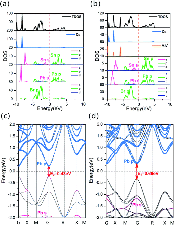
Fig. 5 presents the total density of states (TDOS) and projected density of states (PDOS) using the GGA + SOC method. In all cases, the dominant components of the band edges are similar. The CBM mainly consists of the Sn-5p and Pb-6p electronic states and the VBM is derived from the Sn-5s and Br-4p orbitals, because the original orbital of Sn-5s is higher than the Pb-6s orbital. It is worth noting that the Pb-6s orbitals contribute to the different components of the valance band (VB), as shown in Fig. 5(c) and (d). By comparing the same mixture ratio of the Sn–Pb compounds, we found that the Pb-6s orbital contributes to the lower energy states of the VB in CsSn0.5Pb0.5Br3, whilst for MA0.5Cs0.5Sn0.5Pb0.5Br3 it contributes to the higher energy levels. This also means that the main component of the VBM, the Sn-5s orbitals, are pushed higher in the MA0.5Cs0.5Sn0.5Pb0.5Br3 perovskite, reducing its band gap to x = 0.5. Through studying these all-inorganic systems, it can be seen that a change in the mixture ratio does not affect the bowing parameter due to its distinguished structural configuration. As a result, a reduction in the band gap, in order to obtain a smaller optimal Eg value, is restricted in an all-inorganic perovskite. Furthermore, the PDOS of CsSn0.5Pb0.5Br3 and MA0.5Cs0.5Sn0.5Pb0.5Br3, as seen in Fig. 5(a) and (b), were calculated and the results stated that the Pb-6s states deviated from the VBM, which is lower in the CsSn0.5Pb0.5Br3 system, as indicated by the pink lines.
Conclusions
In summary, we have investigated the structural and electronic properties of the all-inorganic perovskite CsSn1−xPbxBr3 and MAyCs1−ySn1−xPbxBr3 materials. Noticeably, our calculations demonstrated that the occupation sites of the Sn and Pb atoms show distinguishable features in these two mixed compounds. For the all-inorganic CsSn1−xPbxBr3 perovskite, the Sn and Pb atoms preferred to remain scattered in the most stable configuration. The structural characteristics of the inorganic perovskite influenced its electronic properties, and this was eminent in the MAyCs1−ySn1−xPbxBr3 perovskite. It was interesting to discover that the bowing band parameter of CsSn1−xPbxBr3 was the smallest amongst all the perovskite materials studied. As a result, an unexpected electronic deficiency was observed in CsSn1−xPbxBr3, as the band gap of the Sn–Pb mixed structures cannot be reduced significantly for the ideal theoretical PCE. Herein, we provide fundamental understanding of the influence of cations on bowing band evolution and a useful strategy for tuning the electronic properties of mixed perovskite systems.Conflicts of interest
The authors declare no competing financial interests.Acknowledgements
This work is supported by the National Natural Science Foundation of China (Grant No. 61674070, 11804117, 61934004 and 21973034), the Natural Science Foundation of Guangdong Province (Grant No. 2019B151502049) and the Fundamental Research Funds for the Central Universities (Grant No. 21618313). Computer time at the National Supercomputer Center in Guangzhou (NSCCGZ) and the High-Performance Computing Platform of Jinan University is gratefully acknowledged. T. S. and P. L. also acknowledge the Guangzhou Key Laboratory of Vacuum Coating Technologies and New Energy Materials (201605030008).References
- A. Kojima, K. Teshima, Y. Shirai and T. Miyasaka, J. Am. Chem. Soc., 2009, 131, 6050–6051 CrossRef CAS PubMed.
- H. S. Kim, C. R. Lee, J. H. Im, K. B. Lee, T. Moehl, A. Marchioro, S. J. Moon, R. Humphry-Baker, J. H. Yum, J. E. Moser, M. Grätzel and N. G. Park, Sci. Rep., 2012, 2, 1–7 Search PubMed.
- W. S. Yang, J. H. Noh, N. J. Jeon, Y. C. Kim, S. Ryu, J. Seo and S. Il Seok, Science, 2015, 348, 1234–1237 CrossRef CAS PubMed.
- D. Bi, C. Yi, J. Luo, J.-D. Décoppet, F. Zhang, S. M. Zakeeruddin, X. Li, A. Hagfeldt and M. Grätzel, Nat. Energy, 2016, 1, 16142 CrossRef CAS.
- Best Research-Cell Efficiency Chart, http://www.nrel.gov/pv/cell-efficiency.html, accessed, June 16, 2020 Search PubMed.
- T. Zhang, M. I. Dar, G. Li, F. Xu, N. Guo, M. Grätzel and Y. Zhao, Sci. Adv., 2017, 3, 1–7 Search PubMed.
- Y. Chen, T. Shi, P. Liu, W. Xie, K. Chen, X. Xu, L. Shui, C. Shang, Z. Chen, H. L. Yip, G. Zhou and X. Wang, J. Mater. Chem. A, 2019, 7, 20201–20207 RSC.
- J. Wang, J. Zhang, Y. Zhou, H. Liu, Q. Xue, X. Li, C. C. Chueh, H. L. Yip, Z. Zhu and A. K. Y. Jen, Nat. Commun., 2020, 11, 1–9 Search PubMed.
- M. Kulbak, S. Gupta, N. Kedem, I. Levine, T. Bendikov, G. Hodes and D. Cahen, J. Phys. Chem. Lett., 2016, 7, 167–172 CrossRef CAS PubMed.
- C. Liu, W. Li, C. Zhang, Y. Ma, J. Fan and Y. Mai, J. Am. Chem. Soc., 2018, 140, 3825–3828 CrossRef CAS PubMed.
- C. Y. Chen, H. Y. Lin, K. M. Chiang, W. L. Tsai, Y. C. Huang, C. S. Tsao and H. W. Lin, Adv. Mater., 2017, 29, 1–7 Search PubMed.
- Y. Wang, X. Liu, T. Zhang, X. Wang, M. Kan, J. Shi and Y. Zhao, Angew. Chem., Int. Ed., 2019, 58, 16691–16696 CrossRef CAS PubMed.
- Y. Dong, Y. Gu, Y. Zou, J. Song, L. Xu, J. Li, J. Xue, X. Li and H. Zeng, Small, 2016, 12, 5622–5632 CrossRef CAS PubMed.
- Y. Ling, Y. Tian, X. Wang, J. C. Wang, J. M. Knox, F. Perez-Orive, Y. Du, L. Tan, K. Hanson, B. Ma and H. Gao, Adv. Mater., 2016, 28, 8983–8989 CrossRef CAS PubMed.
- N. K. Kumawat, A. Dey, A. Kumar, S. P. Gopinathan, K. L. Narasimhan and D. Kabra, ACS Appl. Mater. Interfaces, 2015, 7, 13119–13124 CrossRef CAS PubMed.
- Z. Yang, X. Zhang, W. Yang, G. E. Eperon and D. S. Ginger, Chem. Mater., 2020, 32, 2782–2794 CrossRef CAS.
- W. Shockley and H. J. Queisser, J. Appl. Phys., 1961, 32, 510–519 CrossRef CAS.
- A. Swarnkar, A. R. Marshall, E. M. Sanehira, B. D. Chernomordik, D. T. Moore, J. A. Christians, T. Chakrabarti and J. M. Luther, Science, 2016, 354, 92–95 CrossRef CAS PubMed.
- Z. Guan, Y. Wu, P. Wang, Q. Zhang, Z. Wang, Z. Zheng, Y. Liu, Y. Dai, M. H. Whangbo and B. Huang, Appl. Catal., B, 2019, 245, 522–527 CrossRef CAS.
- E. M. Sanehira, A. R. Marshall, J. A. Christians, S. P. Harvey, P. N. Ciesielski, L. M. Wheeler, P. Schulz, L. Y. Lin, M. C. Beard and J. M. Luther, Sci. Adv., 2017, 3, eaao4204 CrossRef PubMed.
- F. Hao, C. C. Stoumpos, R. P. H. Chang and M. G. Kanatzidis, J. Am. Chem. Soc., 2014, 136, 8094–8099 CrossRef CAS PubMed.
- A. R. Denton and N. W. Ashcroft, Phys. Rev. A, 1991, 43, 3161–3164 CrossRef CAS PubMed.
- J. Im, C. C. Stoumpos, H. Jin, A. J. Freeman and M. G. Kanatzidis, J. Phys. Chem. Lett., 2015, 6, 3503–3509 CrossRef CAS PubMed.
- L. Zeng, Z. Chen, S. Qiu, J. Hu, C. Li, X. Liu, G. Liang, C. J. Brabec, Y. Mai and F. Guo, Nano Energy, 2019, 66, 104099 CrossRef CAS.
- G. Kresse and J. Furthmüller, Phys. Rev. B, 1996, 54, 11169–11186 CrossRef CAS PubMed.
- G. Kresse and D. Joubert, Phys. Rev. B, 1999, 59, 1758–1775 CrossRef CAS.
- J. P. Perdew, K. Burke and M. Ernzerhof, Phys. Rev. Lett., 1996, 77, 3865–3868 CrossRef CAS PubMed.
- J. P. Perdew and W. Yue, Phys. Rev. B, 1986, 33, 8800–8802 CrossRef PubMed.
- J. D. Pack and H. J. Monkhorst, Phys. Rev. B, 1976, 13, 5188–5192 CrossRef.
- J. Heyd, G. E. Scuseria and M. Ernzerhof, J. Chem. Phys., 2003, 118, 8207–8215 CrossRef CAS.
- C. Adamo and V. Barone, J. Chem. Phys., 1999, 110, 6158–6170 CrossRef CAS.
- E. Narsimha Rao, G. Vaitheeswaran, A. H. Reshak and S. Auluck, Phys. Chem. Chem. Phys., 2017, 19, 31255–31266 RSC.
- J. Even, L. Pedesseau, J. M. Jancu and C. Katan, J. Phys. Chem. Lett., 2013, 4, 2999–3005 CrossRef CAS.
- C. Filippi, D. J. Singh and C. J. Umrigar, Phys. Rev. B, 1994, 50, 14947–14951 CrossRef CAS PubMed.
- K. Momma and F. Izumi, J. Appl. Crystallogr., 2008, 41, 653–658 CrossRef CAS.
- V. M. Goldschmidt, Naturwissenschaften, 1926, 14, 477–485 CrossRef CAS.
- A. Swarnkar, W. J. Mir and A. Nag, ACS Energy Lett., 2018, 3, 286–289 CrossRef CAS.
- R. D. Shannon, Acta Crystallogr., Sect. A, 1976, 32, 751–767 CrossRef.
- M. Wang, G. T. Fei, Y. G. Zhang, M. G. Kong and L. De Zhang, Adv. Mater., 2007, 19, 4491–4494 CrossRef CAS.
- J. A. Van Vechten and T. K. Bergstresser, Phys. Rev. B, 1970, 1, 3351–3358 CrossRef.
- A. A. El-Shazly, M. M. H. El-Naby, M. A. Kenawy, M. M. El-Nahass, H. T. El-Shair and A. M. Ebrahim, Appl. Phys. A, 1985, 36, 51–53 CrossRef.
- S. Larach, R. E. Shrader and C. F. Stocker, Phys. Rev., 1957, 108, 587–589 CrossRef CAS.
- D. Sabba, H. K. Mulmudi, R. R. Prabhakar, T. Krishnamoorthy, T. Baikie, P. P. Boix, S. Mhaisalkar and N. Mathews, J. Phys. Chem. C, 2015, 119, 1763–1767 CrossRef CAS.
- J. Liang, P. Zhao, C. Wang, Y. Wang, Y. Hu, G. Zhu, L. Ma, J. Liu and Z. Jin, J. Am. Chem. Soc., 2017, 139, 14009–14012 CrossRef CAS PubMed.
Footnotes |
| † Electronic supplementary information (ESI) available. See DOI: 10.1039/d0ra03709e |
| ‡ These authors contribute equally to this work. |
| This journal is © The Royal Society of Chemistry 2020 |

