 Open Access Article
Nano-MOF@defected film C3N4 Z-scheme composite for visible-light photocatalytic nitrogen fixation†
Zhu Ding,
Shuo Wang,
Xue Chang,
Dan-Hong Wang * and
Tianhao Zhang*
School of Materials Science and Engineering, School of Physics, Tianjin Key Laboratory of Photonics Materials and Technology for Information Science, Nankai University, Tianjin 300350, China. E-mail: zhangth@nankai.edu.cn
First published on 13th July 2020
Abstract
Photocatalytic nitrogen fixation has attracted extensive attention in recent years. Studies have shown that catalytic materials with O, N and other defects can effectively reduce the bond energy of N![[triple bond, length as m-dash]](https://www.rsc.org/images/entities/char_e002.gif) N triple bond when N2 is adsorbed on the defects. As an outstanding non-metallic catalyst, g-C3N4 has been widely studied in the field of photocatalytic catalysis, and the nitrogen-defected C3N4 shows promoted photocatalytic activity. Herein, nano-size MOF-74 particles (<20 nm) was dispersed on nitrogen-defected C3N4 thin film (∼4 nm) via a simple sol–gel method. The combination of Nano-MOF and defected film C3N4 could effectively improve the photocatalytic activity of nitrogen fixation through Z-scheme mechanism compared with pure defected film C3N4.
N triple bond when N2 is adsorbed on the defects. As an outstanding non-metallic catalyst, g-C3N4 has been widely studied in the field of photocatalytic catalysis, and the nitrogen-defected C3N4 shows promoted photocatalytic activity. Herein, nano-size MOF-74 particles (<20 nm) was dispersed on nitrogen-defected C3N4 thin film (∼4 nm) via a simple sol–gel method. The combination of Nano-MOF and defected film C3N4 could effectively improve the photocatalytic activity of nitrogen fixation through Z-scheme mechanism compared with pure defected film C3N4.
1. Introduction
As an indispensable energy source, ammonia plays an important role in industry and agriculture.1–3 Ammonia is even called “the other hydrogen” in the fuel world.4 The process of ammonia synthesis consumes a huge amount of energy (1–2% of the total world energy consumption) every year, accompanying serious environmental pollution.5,6 Photocatalytic technology can directly convert solar energy into chemical energy.7 In recent years, photocatalytic nitrogen fixation has been widely studied because of its simple reaction conditions, clean and pollution-free reaction process and other advantages.8 However, due to the low utilization rate of visible light and the high recombination rate of photogenic carriers, the photocatalytic activity for nitrogen fixation is relatively poor.9 At the same time, N2 molecules involved in the reaction are relatively stable and difficult to dissociate due to the N![[triple bond, length as m-dash]](https://www.rsc.org/images/entities/char_e002.gif) N triple bond, which shows chemical reaction inertia and poor proton affinity, thus preventing electron transport and Lewis acid–base reaction.10 This poses a serious challenge to photocatalytic materials.11 How to improve the utilization rate of visible light, reduce the recombination of photogenic carriers and weaken the N
N triple bond, which shows chemical reaction inertia and poor proton affinity, thus preventing electron transport and Lewis acid–base reaction.10 This poses a serious challenge to photocatalytic materials.11 How to improve the utilization rate of visible light, reduce the recombination of photogenic carriers and weaken the N![[triple bond, length as m-dash]](https://www.rsc.org/images/entities/char_e002.gif) N triple bond has become the key to improve the activity of photocatalytic nitrogen fixation.12
N triple bond has become the key to improve the activity of photocatalytic nitrogen fixation.12
On account of the high porosity and compatibility, metal–organic frameworks (MOFs) have been studied extensively in the field of photocatalysis in recent years.13,14 The unique properties of MOFs make it convenient to combine with other catalytic materials,15 thus forming new functional composite materials.16 MOFs' channel has a certain adsorption effect on water-soluble nitrogen in water, so as to shorten the distance between water-soluble nitrogen and catalytic sites, and further to weaken the bond energy of N![[triple bond, length as m-dash]](https://www.rsc.org/images/entities/char_e002.gif) N triple bond.17,18 However, MOFs show poor catalytic capacity,19 so they need to be modified or compounded with other active materials to improve photocatalytic activity. For a long time, there has been no in-depth study on the particle size of MOFs,20 and most of them are single crystal with large size (∼μm), and only a handful of MOFs exist in the form of polycrystalline powder due to its synthesis, but most of them are about hundreds of nanometers in size.21 As a result, a majority of the MOFs cannot be well compounded and interact with other materials, so their performances will not be improved. For example, Zn-MOF-74 has the advantages of high stability and high gas absorption capacity.22 However, the single crystal size of Zn-MOF-74 is more than ten to dozens of microns, so large-sized Zn-MOF-74 is difficult to be well combined with some other morphological materials, such as sheet materials.
N triple bond.17,18 However, MOFs show poor catalytic capacity,19 so they need to be modified or compounded with other active materials to improve photocatalytic activity. For a long time, there has been no in-depth study on the particle size of MOFs,20 and most of them are single crystal with large size (∼μm), and only a handful of MOFs exist in the form of polycrystalline powder due to its synthesis, but most of them are about hundreds of nanometers in size.21 As a result, a majority of the MOFs cannot be well compounded and interact with other materials, so their performances will not be improved. For example, Zn-MOF-74 has the advantages of high stability and high gas absorption capacity.22 However, the single crystal size of Zn-MOF-74 is more than ten to dozens of microns, so large-sized Zn-MOF-74 is difficult to be well combined with some other morphological materials, such as sheet materials.
g-C3N4 is also an excellent catalytic material,23 which has been widely used in the field of photocatalysis due to its π-conjugate electron structure, appropriate bandgap width, stable chemical properties and low synthesis cost.24 It has been reported that g-C3N4 with nitrogen vacancy has good photocatalytic nitrogen fixation performance, so the combination of MOFs and defected g-C3N4 may have a good synergistic effect.25,26 So far, people have tried to compound g-C3N4 with ZIF-8,27,28 UiO-66,29,30 MIL31,32 and other MOFs to form some binary heterojunction composite materials.33 It can take the complementary advantages of both MOFs and g-C3N4, overcome their shortcomings and enhance their photocatalytic activity to some extent.34,35 However, the particle size of traditional bulk g-C3N4 is also quite large, and when it is combined with large-sized MOFs, the interaction between them is very weak and there is no good synergistic effect. How to better compound MOFs with g-C3N4 is still of great research significance.36,37 In this work, the particle size of Zn-MOF-74 was achieved to be <20 nm on average, and g-C3N4 is peeled to get thin film (∼4 nm), so that the nanoparticle MOF (Nano-MOF-74) can be easily dispersed on thin film g-C3N4 (F-C3N4). Further, the Nano-MOF-74 can be combined with nitrogen-defected thin film of g-C3N4 (DF-C3N4) to form Z-scheme composite (MOF@DF-C3N4) (Scheme 1). It was found that the MOF@DF-C3N4 composite could effectively improve its photocurrent and photocatalytic activity of nitrogen fixation compared with pure DF-C3N4, and its visible photocatalytic nitrogen fixation yield could reach 2.32 mmol g−1 h−1.
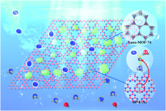 | ||
| Scheme 1 Nano-MOF@defected film C3N4 composite for visible-light photocatalytic nitrogen fixation mechanism. | ||
2. Results and discussion
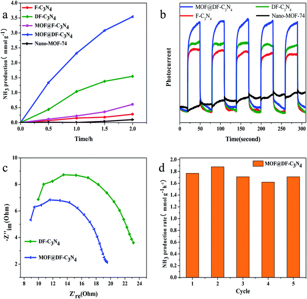
The comparison of photocatalytic nitrogen fixation activity on different catalysts shows that (Fig. 1a) pure Nano-MOF-74(Zn) has basically no visible light catalytic activity, and the visible light activity for F-C3N4 is relatively low. After the combination of Nano-MOF-74 and F-C3N4, the photocatalytic activity is improved to a certain extent, about 2.2 times that of F-C3N4, which indicates that the combination of Nano-MOF-74 and F-C3N4 can improve the photocatalytic activity. When F-C3N4 is made into nitrogen-defected DF-C3N4, its visible light catalytic activity increases significantly. This is due to the existence of nitrogen defects, which can adsorb N2 and reduce the bond energy of N![[triple bond, length as m-dash]](https://www.rsc.org/images/entities/char_e002.gif) N triple bond. Moreover, nitrogen defects can capture photogenic electrons and thus hinder photogenic carrier recombination.38 After the combination of Nano-MOF-74 and DF-C3N4, its photocatalytic nitrogen fixation activity was greatly improved, which was about 2.3 times higher than that of pure DF-C3N4 after 2 h′ light irradiation. According to the results, both F-C3N4 and DF-C3N4 have a good synergistic effect with Nano-MOF-74 and can effectively improve photocatalytic nitrogen fixation activity. At the same time, we conducted relevant experiments to prove its catalytic model (Fig. S1†). According to the activity analysis of the catalyst under light irradiation and no light irradiation, there was no ammonia nitrogen formation in the absence of light, so we considered its catalytic mode as photocatalysis model. The blank visible light photocatalytic experiments on DF-C3N4 are also conducted under Ar and air atmosphere respectively to eliminate the decomposition of DF-C3N4 (Fig. S2†). The reason for using full light spectrum irradiation is to increase its photocatalytic activity to make the contrast more obvious. Ar with a flow rate of 30 ml min−1 was introduced in the sealed reaction solution for 60 min to eliminate the water-soluble N2. The visible light catalytic nitrogen fixation activity is very low under Ar atmosphere. This result also indicates that the nitrogen fixation photocatalytic activity obtained under air atmosphere on DF-C3N4 comes from the decomposition of water-soluble N2.
N triple bond. Moreover, nitrogen defects can capture photogenic electrons and thus hinder photogenic carrier recombination.38 After the combination of Nano-MOF-74 and DF-C3N4, its photocatalytic nitrogen fixation activity was greatly improved, which was about 2.3 times higher than that of pure DF-C3N4 after 2 h′ light irradiation. According to the results, both F-C3N4 and DF-C3N4 have a good synergistic effect with Nano-MOF-74 and can effectively improve photocatalytic nitrogen fixation activity. At the same time, we conducted relevant experiments to prove its catalytic model (Fig. S1†). According to the activity analysis of the catalyst under light irradiation and no light irradiation, there was no ammonia nitrogen formation in the absence of light, so we considered its catalytic mode as photocatalysis model. The blank visible light photocatalytic experiments on DF-C3N4 are also conducted under Ar and air atmosphere respectively to eliminate the decomposition of DF-C3N4 (Fig. S2†). The reason for using full light spectrum irradiation is to increase its photocatalytic activity to make the contrast more obvious. Ar with a flow rate of 30 ml min−1 was introduced in the sealed reaction solution for 60 min to eliminate the water-soluble N2. The visible light catalytic nitrogen fixation activity is very low under Ar atmosphere. This result also indicates that the nitrogen fixation photocatalytic activity obtained under air atmosphere on DF-C3N4 comes from the decomposition of water-soluble N2.
Fig. 1b shows the visible light photocurrent of different catalysts. It can be seen that the photocatalytic nitrogen fixation activity corresponds to the order of the photocurrent. On the one hand, photocurrent is related to the photocarrier concentration of the catalyst, on the other hand, it is related to the recombination of electrons and holes. When the catalysts are exposed to the visible light, the photocurrent of MOF@DF-C3N4 is the highest. This result indicates that the combination of Nano-MOF-74 with DF-C3N4 can effectively reduce the recombination of photogenic electrons and holes and improve the photocarrier concentration. The photocurrent of DF-C3N4 under the visible light irradiation is improved compared with F-C3N4, which indicates that the existence of nitrogen defects can improve the separation ability of photocarriers. As shown in Fig. 1c, compared with pure DF-C3N4, the MOF@DF-C3N4 composite catalyst showed the smaller Nyquist radius, which means the lower charge transfer resistance under the visible light. The low electrical resistance between interfaces is beneficial to the charge transfer and the separation of photogenic electrons and holes. As shown in Fig. 1d, the ammonia production rate is well maintained during five cyclic tests with each run for 2 h. So it can be seen that the catalyst has good reusability and stability.
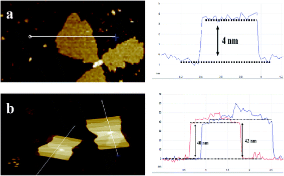
Fig. 2a shows X-ray diffraction patterns of the composites. Nano-MOF-74 has two main peaks at 6.7° and 11.6° respectively, which is consistent with bulk MOF-74 as shown Fig. S3.† For MOF@F-C3N4 and MOF@DF-C3N4 composites, the two main peaks of MOF-74 can still be seen, along with the diffraction peak (002) of g-C3N4, indicating that the two materials of Nano-MOF-74 and g-C3N4 have been successfully combined together. Through STEM dark field image as shown in Fig. 2b and c, we can clearly see the morphology of Nano-MOF-74 and DF-C3N4 (SEM images are shown in Fig. S4†). The particle size of Nano-MOF-74 is <20 nm, which is quite different from the traditional bulk Zn-MOF-74 with a size of ten to dozens of microns. Both F-C3N4 and DF-C3N4 show thin film morphology according to TEM images (Fig. 2d and e). AFM images (Fig. 3) show that F-C3N4 thin film presents a thickness of ∼4 nm compared with bulk C3N4 (∼40 nm). The thin film shows a better morphology and is more conducive to form the composite with Nano-MOF-74. From TEM images for the composites (Fig. 2f and g), we can see that Nano-MOF-74 can be well dispersed on F-C3N4 and DF-C3N4 with a nanosize <20 nm. In accordance with TEM element mapping images for the composites (Fig. S5 and S6†), Zn element is distributed in the nanoparticles and N element is distributed in the nanosheets, indicating the successful combination of Nano-MOF-74 and thin film g-C3N4. Moreover, Nano-MOF-74 did not form a wrapping state with C3N4, but dispersed and attached onto the surface of C3N4. If the proportion of Nano-MOF-74 is too high, it will cover the surface photoactive sites of thin film C3N4 and hinder the irradiation of light on thin film C3N4, thus decreasing the photoactivity of nitrogen fixation. Therefore, the combination of a small amount of Nano-MOF-74 (20 wt%) and thin film C3N4 (80 wt%) does not affect the light absorption of thin film C3N4 and increase its photoactivity when they interact with each other.
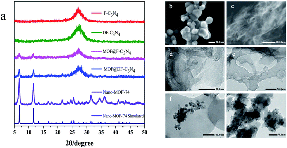 | ||
| Fig. 2 (a) X-ray diffraction patterns of the samples and STEM images of (b) Nano-MOF-74, (c) DF-C3N4 and TEM images of (d) F-C3N4, (e) DF-C3N4, (f) MOF@F-C3N4, (g) MOF@DF-C3N4. | ||
Elemental analysis was used to determine the C/N molar ratio in F-C3N4 and DF-C3N4 and to determine the type of defects formed in the DF-C3N4 framework (Table S1†). The C/N molar ratio of DF-C3N4 was 0.68 (the mass ratio of C is 33.93% and N is 57.95%), which was higher than that of F-C3N4 (0.66, the mass ratio of C is 33.56% and N is 58.84%). This finding indicates that the defects formed in the DF-C3N4 framework were nitrogen vacancies with electrons trapped in as shown in eqn (1). The electrons delocalized in nitrogen vacancies are suggested to play an important role in nitrogen fixation. Thus DF-C3N4 shows higher photocatalytic activity than F-C3N4 as shown in Fig. S9.† The unpaired electrons at g = 2.003 were detected for both F-C3N4 and DF-C3N4 by ESR as shown in Fig. 4a, suggesting the formation of nitrogen vacancies with electrons trapped in. Magnetic susceptibility measurements (Fig. 4b) also proved that an increase in magnetic susceptibility (χmT) is observed for DF-C3N4 compared that for F-C3N4, suggesting the formation of more unpaired electrons captured by nitrogen vacancies for DF-C3N4 than that for F-C3N4.
 | (1) |
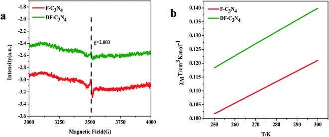 | ||
| Fig. 4 ESR results for F-C3N4 and DF-C3N4 (a) and temperature dependent molar magnetic susceptibility χmT for F-C3N4 and DF-C3N4 (b). | ||
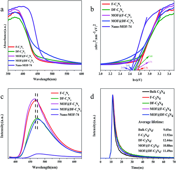
Fig. 5a shows the UV-Vis light absorption spectra of the photocatalysts. The strongest absorption peak of F-C3N4, DF-C3N4, MOF@F-C3N4 and MOF@DF-C3N4 is at 380 nm, and the strongest absorption peak of Nano-MOF-74 is at 400 nm, which are caused by the band transition of the semiconductors. The absorption edge of F-C3N4 is at 450 nm, and F-C3N4 basically has no absorption in the visible light region after 450 nm. Compared with F-C3N4, the absorption of DF-C3N4, MOF@F-C3N4 and MOF@DF-C3N4 have different degrees of redshift. Especially, when Nano-MOF-74 was combined with DF-C3N4 to obtain MOF@DF-C3N4, the absorption in the visible light region was significantly increased, which was also the main reason for the increase in the visible light nitrogen fixation activity. Fig. 5b shows the Kubelka–Munk plots converted from the UV-Vis DRS spectra. The calculated bandgaps for F-C3N4, DF-C3N4, MOF@F-C3N4 and MOF@DF-C3N4 are 2.76, 2.68, 2.71 and 2.65 eV, respectively (Table 1). Compared with F-C3N4 or DF-C3N4, after combining with Nano-MOF-74, the bandgaps of the composites decrease to a certain extent, which is more conducive to the absorption of visible light. Compared with F-C3N4, the narrower energy gap for DF-C3N4 can be explained by the formation of nitrogen vacancies, which results in the introduction of defect bands  under the conduction band (CB). At the same time, it can be seen from Fig. S7† that the absorption edges for F-C3N4 and DF-C3N4 blue-shift compared with bulk C3N4, which corresponding to the color change from pale yellow to deep yellow. The color of Nano-MOF is also lighter than that of bulk MOF-74. As can be seen from the fluorescence spectra in Fig. 5c, the MOF@F-C3N4 or MOF@DF-C3N4 composites basically did not change the fluorescence absorption compared with F-C3N4 or DF-C3N4, respectively. However, compared with F-C3N4, the fluorescence of DF-C3N4 was significantly reduced. The decrease of fluorescence emission indicates that the recombination of photogenic carriers is significantly reduced. This fact can be explained by that nitrogen vacancies in DF-C3N4 can trap electrons and effectively reduce the recombination of electrons and holes, thus improving the photocatalytic activity of nitrogen fixation. The PL emission wavelength for DF-C3N4 (475 nm equals to 2.61 eV) is higher than that for F-C3N4 (465 nm equals to 2.67 eV), which is in good accordance with the band gap obtained from UV-Vis spectra (Table 1). The transient PL decay spectra in Fig. 5d further gives us evident to explain the photocatalytic nitrogen fixation activities. The average PL lifetimes of bulk C3N4, F-C3N4, DF-C3N4, MOF@F-C3N4 and MOF@DF-C3N4 were calculated to be 9.65, 11.92, 12.44, 10.88 and 11.49 ns, respectively. Compared with pure F-C3N4, the relaxation life of pure DF-C3N4 increases, which implies DF-C3N4 with nitrogen defects has a strong trapping ability for electrons to increase the relaxation life.40 While for MOF@F-C3N4 or MOF@DF-C3N4 composites, the relaxation lives decrease compared with pure F-C3N4 or pure DF-C3N4 respectively. This result can be explained by the formation of Z-scheme heterojunction (as described in the next paragraph) leading to high efficiency of charge separation.41 Average relaxation life can be used as an index to evaluate the efficiency of charge separation: the faster the relaxation, the higher the efficiency.42 The fast relaxation life of MOF@DF-C3N4 thus corresponds to the large photogenic carrier separation and the high ammonia production.43
| N2 + 8H+ + 8e− → 2NH4+, 0.27 eV | (2) |
| Sample | Eg (eV) | Average lifetime (ns) |
|---|---|---|
| Bulk C3N4 | 2.62 | 9.65 |
| F-C3N4 | 2.76 | 11.92 |
| DF-C3N4 | 2.68 | 12.44 |
| MOF@F-C3N4 | 2.71 | 10.88 |
| MOF@DF-C3N4 | 2.65 | 11.49 |
| Nano-MOF-74 | 2.63 | — |
Fig. 6a shows the bandgap structures of F-C3N4, Nano-MOF-74 and DF-C3N4. The energies of valence bands (VB) of the three are obtained from XPS valence band spectra (Fig. S8†). Then according to Eg results obtained from UV-Vis spectra (Table 1), the energies of conduction bands can be calculated. The electric potential required for N2 conversion to NH4+ is +0.27 eV (eqn (2)),39 and the conduction band of Nano-MOF-74 is located at +0.77 eV. Thus the electrons on the CB of Nano-MOF-74 cannot cause N2 convert to NH4+, so we speculate that the combination of Nano-MOF-74 with F-C3N4 or DF-C3N4 results in a Z-scheme heterojunction (Fig. 6b). It is beneficial to the application of semiconductor heterostructure in photocatalysis if the photocarrier separation can be realized while maintaining their redox ability. In the semiconductor heterogeneous structure formed by Nano-MOF-74 and DF-C3N4, the photogenic electrons on the CB of Nano-MOF-74 transfer and recombine with the photogenic holes on the VB of DF-C3N4 at the interface. Thus, the photogenic electrons on the CB of DF-C3N4 with stronger reduction capacity and the photogenic holes on the VB of Nano-MOF-74 with stronger oxidation capacity were retained, this is a typical vector Z mechanism carrier transfer. To be sure, in the mechanism of the semiconductor heterostructure, the traditional type II carrier transfer process (the electrons transfer from high CB of DF-C3N4 to low CB of Nano-MOF-74) can still happen (Fig. 6c), it can be seen that the electron should be transferred from the conduction band of DF-C3N4 to the conduction band of Nano-MOF-74, while the hole is transferred from the valence band of Nano-MOF-74 to the valence band of DF-C3N4. The two carrier transfer processes (Z-scheme and type II) are competitive. The results of our fluorescence lifetime test support the Z-scheme for MOF@DF-C3N4 composite, and the position of its conduction band is higher with higher electronic reduction capability, so we believe that the mechanism is mainly Z-scheme instead of type-II scheme. Therefore, nitrogen defects introduced in DF-C3N4 play an important role. Electrons were captured by the nitrogen defects and prevented the electron transfer from the CB of DF-C3N4 to the CB of Nano-MOF-74. In this way, the concentration of photogenic carriers is increased, and the photocatalytic activity of nitrogen fixation is improved.
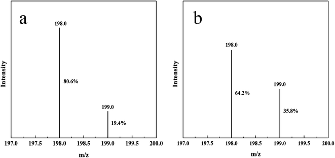
In order to prove that the nitrogen source of ammonia nitrogen products generated by photocatalysis comes from nitrogen, we made isotopic labeling of 15N2. Vacuumed the reactor to change nitrogen, replaced 14N2 with 15N2, and then let it stand for 12 hours. Then, normal photocatalytic reaction was carried out, and the product after the reaction was taken for indophenol method. Through LC-MS analysis, compared with 14N indophenol blue, the content of 15N indophenol blue increased by 16.4% (Fig. 7).The reaction process is shown in the Scheme 2, 15N labeled 15N2 is adsorbed to the N defects on DF-C3N4, and after contact with photogenic electrons, the nitrogen–nitrogen triple bond breaks, and ammonia nitrogen products are generated contact with hydrogen ions.44 So during the process, the nitrogen on DF-C3N4 is not involved in the formation of ammonia, and the nitrogen source in ammonia nitrogen come from the N2.
3. Conclusion
In summary, we successfully combined nano-sized Nano-MOF-74 (Zn) with nitrogen-defected thin film C3N4. The experimental results showed that nitrogen fixation activity of the composite was effectively improved compared with pure DF-C3N4 under visible light irradiation. We speculated that this was mainly due to the formation of Z-scheme heterojunction, which reduced the photogenic carrier recombination. Further, the presence of nitrogen defects can prevent the electron transfer and effectively improve the concentration of photogenic carriers. This provides a new idea for the future work on the combination of MOFs and inorganic materials, and provides a new thought for improving the photoactivity of visible light nitrogen fixation.4. Experimental procedures
2,5-dihydroxy terephthalic acid (2,5-BDC) was purchased from Meryer, Zn(NO3)2·6H2O was purchased from Aladdin, N,N-dimethylformamide (DMF) was purchased from FoChen, melamine was purchased from Kermel, triethylamine and deionized (DI) water were purchased from ConCord. All chemical reagents are A.R grade and are not further purified after purchase from reagent company.4.1 Synthesis of photocatalyst
4.2 Characterization
With 10° min−1 scanning rate, powder X-ray diffraction (XRD) patterns were recorded in the range 3° to 80° on a Rigaku MiniFlex 600 using CuKα radiation (λ = 0.154178 nm) at 298 K. Electrochemical data testing was performed at the Chenhua CHI 760E electrochemical workstation. The samples' morphologies were analyzed through JSM-7800F scanning electron microscope (SEM). Using a JEM-2800 microscope high-resolution TEM (HRTEM) images were tested. The UV-Vis measurement of the samples was carried out by a spectrophotometer with TU-1950 PERSEE. Steady-state fluorescence spectra were measured by HITACHI F-7000. The measurement of fluorescence lifetime was performed by FLS920 transient fluorescence/phosphorescence spectrometer (77–500 K). Atomic force microscope (AFM, Bruker Dimension Icon) was used to measure the thickness of samples. Magnetic susceptibility measurements were performed with MPMS3 from Quantum Design. The data were measured from 300 K to 250 K at 1000 Oe direct-current field. Data were corrected for the diamagnetic contribution calculated from Pascal constants. Unpaired electrons were detected using an ESR spectrometer (EMX plus-6/1) at room temperature.4.3 Photocatalytic N2 reduction reaction measurements
Photocatalytic nitrogen fixation reaction is carried out in Zhong Jiao Jin Yuan photocatalytic reactor (CEL-APR100H). 10 mg photocatalyst was added to the mixed solution of 48 ml H2O and 2 ml methanol (as the hole trapping agent) for 15 min ultrasound, and then transferred to the photocatalytic reactor for sealing. The reactor controlled the reaction temperature at 25 °C by circulating condensed water and the reaction was carried on under atmospheric pressure with magnetic stirring. The light source is 300 W Xe lamp (CEL-HXF300) about 15 cm away from the photocatalytic reactor with a cut-off filter (400 nm) for visible-light photocatalysis. During the illumination, 1 ml solution was taken every half an hour to detect NH4+ content by the Nessler reagent method at 420 nm with an ultraviolet spectrophotometer (KU-T6PC).4.4 Photocurrent experiments
10 mg samples were dispersed in 1 ml ethanol for half an hour by ultrasound, and the samples were uniformly coated on ITO glass with the area of 1 × 1 cm. Then vacuum dried the conductive glass coated with the sample for 10 h to make the sample and conductive glass combine more firmly. The photocurrent test was carried out in a quartz pool with ITO conductive glass coated with the sample as the working electrode, a Pt foil as counter electrode and an Ag/AgCl electrode as reference electrode, and the electrolyte was Na2SO4 (0.1 M) aqueous solution. In visible light photocurrent tests, the ultraviolet light is filtered out using a 400 nm filter under a 300 W Xe lamp.The electrochemical impedance spectra (EIS) were recorded when the initial voltage is open circuit voltage over the frequency range of 1 MHz to 1 Hz under illumination condition.
4.5 N-15 labeling experiments
The catalyst and sacrificial agent of the same amount as the normal photocatalytic reaction were added to 48 ml water for 10 min after ultrasonic treatment, and then poured into the reactor. A circulating water pump was used to vacuum the reactor and replace 14N2 with 15N2. After 2 hours of reaction, 0.5 ml of the reaction liquid filtered through the filter membrane was taken and mixed with 0.1 ml of 1% phenolic solution in 95% ethanol/water, 0.375 ml of 1% NaClO in alkaline Na-citrate solution in water and 0.5 ml of 0.5% Na [Fe(CN)5NO] in water for reaction. After 12 hours until fully developed, it was tested by LC-MS.46Conflicts of interest
There are no conflicts to declare.Acknowledgements
This work was partly supported by Natural Science Foundation of China (21576140) and Natural Science Foundation of Tianjin (17JCYBJC20000, 19JCTPJC46300).References
- B. K. Burgess and D. J. Lowe, Mechanism of Molybdenum Nitrogenase, Chem. Rev., 1996,(7), 2983–3012 CrossRef CAS PubMed.
- R. Chandra and M. J. C. Nath, Multi-Core–shell TiO2 NPs@ZIF-8 Composite for Enhanced Photocatalytic Degradation and Adsorption of Methylene Blue and Rhodamine-B, ChemistrySelect, 2017, 2(25), 7711–7722 CrossRef CAS.
- S. Chen, T. Takata and K. J. N. R. M. Domen, Particulate photocatalysts for overall water splitting, Nat. Rev. Mater., 2017, 2, 17050 CrossRef CAS.
- S. Cong, Y. Yuan, Z. Chen, J. Hou, M. Yang, Y. Su, Y. Zhang, L. Li, Q. Li and F. Geng, Noble metal-comparable SERS enhancement from semiconducting metal oxides by making oxygen vacancies, Nat. Commun., 2015, 6(6–7), 7800 CrossRef CAS PubMed.
- J. W. Erisman, M. A. Sutton and J. Galloway, et al., How a century of ammonia synthesis changed the world, Nat. Geosci., 2008, 1(10), 636–639 CrossRef CAS.
- H. Guo, D. Guo and Z. Zheng, et al., Visible-light photocatalytic activity of Ag@MIL-125(Ti) microspheres, Appl. Organomet. Chem., 2015, 29(9), 618–623 CrossRef CAS.
- H. Hirakawa, M. Hashimoto and Y. Shiraishi, et al., Photocatalytic Conversion of Nitrogen to Ammonia with Water on Surface Oxygen Vacancies of Titanium Dioxide, J. Am. Chem. Soc., 2017, 139(31), 10929–10936 CrossRef CAS PubMed.
- K. Honkala, A. Hellman and I. N. Remediakis, et al., Ammonia Synthesis from First-Principles Calculations, Science, 2005, 307(5709), 555–558 CrossRef CAS PubMed.
- L. Jiang, L. Y. Sun and X. D. Pan, et al., Characterization of the unique Chinese W483X mutation in the low-density lipoprotein (LDL)-receptor gene in young patients with homozygous familial hypercholesterolemia, J. Clin. Lipidol., 2015, 10(3), 538–546.e5 CrossRef PubMed.
- X. Cao, C. Li and Y. Li, et al., Enhanced performance of perovskite solar cells by modulating Lewis acid-base reaction, Nanoscale, 2016, 19804–19810 RSC.
- J. Li, H. Li and G. Zhan, et al., Solar Water Splitting and Nitrogen Fixation with Layered Bismuth Oxyhalides, Acc. Chem. Res., 2017, 50(1), 112–121 CrossRef CAS PubMed.
- X. Li, J. Iocozzia and Y. Chen, et al., Functional Nanoparticles Enabled by Block Copolymer Templates: from Precision Synthesis of Block Copolymers to Properties and Applications of Nanoparticles, Angew. Chem., 2017, 2046–2070 Search PubMed.
- X. Deng, L. Yang and H. Huang, et al., Shape-Defined Hollow Structural Co-MOF-74 and Metal Nanoparticles@Co-MOF-74 Composite through a Transformation Strategy for Enhanced Photocatalysis Performance, Small, 2019, e1902287 CrossRef PubMed.
- C. Xu, Y. Pan, G. Wan, H. Liu, L. Wang, H. Zhou, S. H. Yu and H. L. Jiang, Turning on Visible-Light Photocatalytic C-H Oxidation over Metal-Organic Frameworks by Introducing Metal-to-Cluster Charge Transfer, J. Am. Chem. Soc., 2019, 141(48), 19110–19117 CrossRef CAS PubMed.
- T. He, B. Ni and S. Zhang, et al., Ultrathin 2D Zirconium Metal–Organic Framework Nanosheets: Preparation and Application in Photocatalysis, Small, 2018, 14, 1703929 CrossRef PubMed.
- V. Singh, I. J. C. Beltran, J. C. Ribot and P. Nagpal, Photocatalysis Deconstructed: Design of a New Selective Catalyst for Artificial Photosynthesis, Nano Lett., 2014, 14(2), 597–603 CrossRef CAS PubMed.
- N. L. Rosi, J. Kim, M. Eddaoudi, B. Chen, M. O'Keeffe and O. M. Yaghi, Rod Packings and Metal–Organic Frameworks Constructed from Rod-Shaped Secondary Building Units, J. Am. Chem. Soc., 2005, 127(5), 1504–1518 CrossRef CAS PubMed.
- L. Valenzano, B. Civalleri, S. Chavan, G. T. Palomino, C. O. Areán and S. Bordiga, Computational and Experimental Studies on the Adsorption of CO, N2, and CO2 on Mg-MOF-74, J. Phys. Chem. C, 2010, 114(25), 11185–11191 CrossRef CAS.
- J. D. Xiao and H. L. Jiang, Thermally Stable Metal-Organic Framework-Templated Synthesis of Hierarchically Porous Metal Sulfides: Enhanced Photocatalytic Hydrogen Production, Small, 2017, 1700632 CrossRef PubMed.
- Y. Z. Chen, B. Gu, T. Uchida, J. Liu, X. Liu, B. J. Ye, Q. Xu and H. L. Jiang, Location determination of metal nanoparticles relative to a metal-organic framework, Nat. Commun., 2019, 10(1), 3462 CrossRef PubMed.
- J. W. F. To, J. He and J. Mei, et al., Hierarchical N-Doped Carbon as CO2 Adsorbent with High CO2 Selectivity from Rationally Designed Polypyrrole Precursor, J. Am. Chem. Soc., 2015, 138(3), 1001–1009 CrossRef PubMed.
- J. L. C. Rowsell and O. M. Yaghi, Effects of Functionalization, Catenation, and Variation of the Metal Oxide and Organic Linking Units on the Low-Pressure Hydrogen Adsorption Properties of Metal Organic Frameworks, J. Am. Chem. Soc., 2006, 128(4), 1304–1315 CrossRef CAS PubMed.
- D. A. Giannakoudakis, N. A. Travlou and J. Secor, et al., Oxidized g-C3N4 Nanospheres as Catalytically Photoactive Linkers in MOF/g-C3N4 Composite of Hierarchical Pore Structure, Small, 2016, 13(1), 1601758 CrossRef PubMed.
- X. Zhang, X. Xie and H. Wang, et al., Enhanced Photoresponsive Ultrathin Graphitic-Phase C3N4 Nanosheets for Bioimaging, J. Am. Chem. Soc., 2012, 135, 18–21 CrossRef PubMed.
- X. Zhang, H. Wang, H. Wang, Q. Zhang, J. Xie, Y. Tian, J. Wang and Y. Xie, Single-Layered Graphitic-C3N4 Quantum Dots for Two-Photon Fluorescence Imaging of Cellular Nucleus, Adv. Mater., 2014, 26(26), 4438–4443 CrossRef CAS PubMed.
- Q. Liu, L. Ai and J. Jiang, MXene-derived TiO2@C/g-C3N4 heterojunctions for highly efficient nitrogen photofixation, J. Mater. Chem. A, 2018, 6, 4102–4110 RSC.
- W. Tang, X. Wu and Y. Chen, Catalytic removal of gaseous benzene over Pt/SBA-15 catalyst: the effect of the preparation method, React. Kinet., Mech. Catal., 2015, 114(2), 711–723 CrossRef CAS.
- Q. Liao, Z. Xie and B. Pan, et al., LC–MS–MS Simultaneous Determination of Paracetamol, Pseudoephedrine and Chlorpheniramine in Human Plasma: Application to a Pharmacokinetic Study, Chromatographia, 2008, 67(s. 9–10), 687–694 CrossRef CAS.
- R. Wang, L. Gu and J. Zhou, et al., Quasi-Polymeric Metal–Organic Framework UiO-66/g-C3N4 Heterojunctions for Enhanced Photocatalytic Hydrogen Evolution under Visible Light Irradiation, Adv. Mater. Interfaces, 2015, 2, 1500037 CrossRef.
- G. Liu and W. Tao, et al., Nature-Inspired Environmental “Phosphorylation” Boosts Photocatalytic H2 Production over Carbon Nitride Nanosheets under Visible-Light Irradiation., Angew. Chem., 2015, 127(46), 13765–13769 CrossRef.
- H. Guo, F. Lin and J. Chen, et al., Metal-organic framework MIL-125(Ti) for efficient adsorptive removal of Rhodamine B from aqueous solution, Appl. Organomet. Chem., 2015, 29(1), 12–19 CrossRef CAS.
- C. Bai, J. Bi and J. Wu, et al., Fabrication of noble-metal-free g-C3N4-MIL-53(Fe) composite for enhanced photocatalytic H2-generation performance, Appl. Organomet. Chem., 2018, 32, e4597 CrossRef.
- C. C. Wang and Y. S. Ho, Research trend of metal–organic frameworks: a bibliometric analysis, Scientometrics, 2016, 109(1), 481–513 CrossRef.
- S. D. Han, W. C. Song and J. P. Zhao, et al., Synthesis and ferrimagnetic properties of an unprecedented polynuclear cobalt complex composed of [Co_(24)] macrocycles, Chem. Commun., 2013, 49(9), 871–873 RSC.
- H. Fu, Z. Wang, W. Xun, W. Peng and C. C. Wang, Formation mechanism of rod-like ZIF-L and fast phase transformation from ZIF-L to ZIF-8 with morphology changes controlled by polyvinylpyrrolidone and ethanol, CrystEngComm, 2018, 20(11), 1473–1477 RSC.
- J. Liu, Y. Liu and N. Liu, et al., Metal-free efficient photocatalyst for stable visible water splitting via a two-electron pathway, Science, 2015, 347(23), 970–974 CrossRef CAS PubMed.
- G. Gao, Y. Jiao and F. Ma, et al., Carbon nanodot decorated graphitic carbon nitride: new insights into the enhanced photocatalytic water splitting from ab initio studies, Phys. Chem. Chem. Phys., 2015, 17(46), 31140–31144 RSC.
- G. Dong, W. Ho and C. Wang, Selective photocatalytic N2 fixation dependent on g-C3N4 induced by nitrogen vacancies, J. Mater. Chem. A, 2015, 3(46), 23435–23441 RSC.
- S. Yasuhiro, et al., Nitrogen Fixation with Water on Carbon-Nitride-Based Metal-Free Photocatalysts with 0.1% Solar-to-Ammonia Energy Conversion Efficiency, ACS Appl. Energy Mater., 2018, 8b00829 Search PubMed.
- P. Qiu, C. Xu and N. Zhou, Metal-free black phosphorus nanosheets-decorated graphitic carbon nitride nanosheets with C-P bonds for excellent photocatalytic nitrogen fixation, Appl. Catal., B, 2018, 221, 27–35 CrossRef CAS.
- H. L. Jiang, X. Ma and L. Wang, et al., Switching on Photocatalysis of Metal–Organic Frameworks by Engineering Structural Defects, Angew. Chem., 2019, 131(35), 12303–12307 CrossRef.
- H. Diarmand-Khalilabad, A. Habibi-Yangjeh and D. Seifzadeh, et al., g-C3N4 nanosheets decorated with carbon dots and CdS nanoparticles: Novel nanocomposites with excellent nitrogen photofixation ability under simulated solar irradiation, Ceram. Int., 2018, 45(2), 2542–2555 CrossRef.
- H. Wang, et al., MIL-100(Fe)/Ti3C2 MXene as a Schottky Catalyst with Enhanced Photocatalytic Oxidation for Nitrogen Fixation Activities, ACS Appl. Mater. Interfaces, 2019, 11(47), 44249–44262 CrossRef CAS PubMed.
- C. Lv, Y. Qian and C. Yan, et al., Defect Engineering Metal-Free Polymeric Carbon Nitride Electrocatalyst for Effective Nitrogen Fixation under Ambient Conditions, Angew. Chem., 2018, 130(32), 10403–10407 CrossRef.
- G. Li, et al., Fe-based MOFs for photocatalytic N2 reduction: Key role of transition metal iron in nitrogen activation, J. Solid State Chem., 2020, 285, 121245 CrossRef CAS.
- S. J. Geromanos, J. P. Vissers and J. C. Silva, et al., The detection, correlation, and comparison of peptide precursor and product ions from data independent LC-MS with data dependant LC-MS/MS, Proteomics, 2009, 9(6), 1683 CrossRef CAS PubMed.
Footnote |
| † Electronic supplementary information (ESI) available. See DOI: 10.1039/d0ra03562a |
| This journal is © The Royal Society of Chemistry 2020 |

