DOI:
10.1039/D0RA03233F
(Paper)
RSC Adv., 2020,
10, 23554-23565
Facile one-pot synthesis of heterostructure SnO2/ZnO photocatalyst for enhanced photocatalytic degradation of organic dye†
Received
10th April 2020
, Accepted 14th June 2020
First published on 22nd June 2020
Abstract
In this work, heterostructure SnO2/ZnO nanocomposite photocatalyst was prepared by a straightforward one step polyol method. The resulting photocatalysts were characterized by X-ray diffraction (XRD), nitrogen adsorption–desorption analyses, transmission electron microscopy (TEM), X-ray photoelectron spectroscopy (XPS) and UV-vis diffuse reflectance spectroscopy (UV-vis DRS). The results showed that the synthesized SnO2/ZnO nanocomposites possessed mesoporous wurtzite ZnO and cassiterite SnO2 nanocrystallites. The photocatalytic activity of the prepared SnO2/ZnO photocatalyst was investigated by the degradation of methylene blue dye under UV light irradiation. The heterostructure SnO2/ZnO photocatalyst showed much higher photocatalytic activities for the degradation of methylene blue dye than individual SnO2, ZnO nanomaterials and reference commercial TiO2 P25. This higher photocatalytic degradation activity was due to enhanced charge separation and subsequently the suppression of charge recombination in the SnO2/ZnO photocatalyst resulting from band offsets between SnO2 and ZnO. Finally, these heterostructure SnO2/ZnO nanocatalysts were stable and could be recycled several times without any appreciable change in degradation rate constant which opens new avenues toward potential industrial applications.
Introduction
The continuing propagation of industrialization and urbanization produces large amounts of wastewater containing organic substances such as pesticides, insecticides, dyes, phenolic compounds, toxic organics, and heavy metals (lead, cadmium, arsenic, mercury, etc.), as well as microbial pathogens. Among these, synthetic dyes are valuable in numerous industries such as textiles, paper printing, food, pharmaceuticals, leather and cosmetics.1,2 A substantial amount of water is consumed in the textile industry for manufacturing processes.3 The wastewater from textile plants is classified as the most polluting of all the industrial sectors, considering the volume generated as well as the effluent composition.4,5 Discharge of dyeing industry wastewater into natural water bodies is not desirable as the color prevents re-oxygenation in receiving water by cutting off penetration of sunlight.6 Most of the dyes, even in very low concentration, are toxic to some microorganisms, aquatic life and human beings as they are carcinogenic and mutagenic.7–10 Thus, finding a sustainable solution to treat the dye containing wastewater is of high priority in terms of environmental pollution remediation.
Various approaches on handling and decontamination of effluents have been reported in the literature.11–13 Currently available water treatment technologies such as adsorption or coagulation merely concentrate the pollutants present by transferring them to other phases, but still remain and not being completely eliminated or destroyed. Other conventional water treatment methods such as sedimentation, filtration, chemical and membrane technologies involve high operating costs and could generate toxic secondary pollutants into the ecosystem.14 These concentrated toxic contaminants are highly redundant and have been concerned worldwide due to the increasing environmental awareness and legislations. Therefore, it is a challenge today to develop sustainable and economically viable technology to treat, recycle and reuse of dye containing wastewater. In these cases, it is necessary to adopt reactive systems much more effective than those adopted in conventional purification processes. Therefore, the development of eco-friendly methods of destroying these pollutants became an imperative task.
Over the past decade, many research efforts have been devoted around the world to develop a newer, more powerful, and very promising technique called Advanced Oxidation Processes (AOPs) to treat the contaminants of industrial effluents.15–18 Among these AOPs, heterogeneous photocatalysis using semiconductor photocatalysts such as titanium dioxide (TiO2),19,20 zinc oxide,21–23 tin oxide (SnO2),24,25 can be suitably pertained for the photocatalytic degradation of organic pollutants because it can mineralize dye molecules into CO2, H2O and mineral acids without producing secondary pollution. Furthermore, the photocatalysts are cheap, non-hazardous, stable, biologically and chemically inert, insoluble under most conditions and reusable. Typically, when a semiconductor photocatalyst is irradiated with photon of energy equal to or greater than the band gap energy of the semiconductor, then the electron from the filled valence band is excited to the conduction band leaving photogenerated holes in the valence band. After excitation the photogenerated holes and electrons migrate to the surface and take part in the redox reaction and mineralize the organic compounds to degradation products, generally to H2O and CO2. Among different semiconductor metal oxides, zinc oxide (ZnO) has been considered as a suitable alternative to titania owing to its non-toxicity, close band-gap energy (3.37 eV), high electron mobility (205–1000 cm2 V−1 s−1), large excitation binding energy (60 meV), straightforward tailoring of the nanostructures and easy modification of the surface structure.26,27 Thus, ZnO showed better efficiency than TiO2 in the photocatalytic decomposition of organic dyes either in organic or in aqueous media.28 However, the fast recombination rate of photogenerated electron–hole pairs has hampered the industrial applications of ZnO. One interesting way to overcome such limitations and to achieve efficient charge separation is to couple ZnO with other semiconductor metal oxides having suitable band positions. In this context, various semiconductor based heterostructure photocatalysts have been designed and investigated such as Fe3O4/ZnO,29 CeO2/ZnO,30 ZnO–WO3−x,31 SnO2/TiO2,32,33 TiO2/ZnO,34,35 CuO/ZnO.36 Recently, Ahmad et al. develop ZnO-decorated polypyrrole/chitosan bio-nanocomposites by in situ polymerization of pyrrole in order to enhance the photocatalytic activity for the degradation of organic dyes.37 The resulting composite showed higher photocatalytic performance for the degradation of methylene blue, reactive orange-16 and Coomassie brilliant blue R-250 under UV light irradiation. The enhanced photocatalytic degradation of the composite resulted from the low recombination rate of the electron–hole pairs evidenced by decreased PL intensity. In order to obtain visible light active photocatalyst, Di et al. synthesized ZnO–GO coupled chitin graphene hydrogel (ZnO–GO/CGH) for degrading methylene blue.38 The as-synthesized nanocomposite exhibited higher photocatalytic activity for the degradation of methylene blue under visible light irradiation. The higher activity was due to the improved charge separation resulting from the movement of the photogenerated holes and electrons to different locations on the surface of ZnO–GO/CGH, In another study, Wang et al. fabricated ZnO p–n homojunctions by depositing n-type ZnO nanoparticles on the surface of p-type ZnO nanoparticles.39 The ZnO with oxygen vacancy and metal vacancy resulted n-type ZnO and p-type ZnO, respectively. The built-in potential at p–n homojunction decreased the recombination of photogenerated hole–electron by transfer the charge carriers in opposite direction leading to the higher photocatalytic performance of ZnO p–n homojunction than the p-type ZnO and n-type ZnO for the degradation of phenol and methyl orange.
It is reported that tin dioxide (SnO2) is an n-type semiconductor that has a wide range of potential applications in gas sensors, catalysts, batteries, transistors, and transparent electrodes.40–43 SnO2 has a wide band gap of 3.6 eV at room temperature with excellent optical and electrical properties.44 Moreover, SnO2 possesses a high electron mobility (∼100–200 cm2 V−1 s−1), indicating a faster transport of photoexcited electrons. In addition, the conduction band of SnO2 is more positive (0.5 V) than that of ZnO and could act as a sink for the photogenerated electrons.45,46 Thus, tin oxide (SnO2) can be combined with ZnO to reduce the recombination of photogenerated electrons and holes owing to its outstanding physical and chemical properties. Using SnO2 coupled to ZnO, the photogenerated electrons can accumulate on the SnO2 and the photogenerated holes can accumulate on the ZnO owing to the formation of heterojunction at the SnO2/ZnO. As a consequence, coupling of SnO2 with ZnO has been the subject of many research groups for achieving an efficient charge separation and improving the photocatalytic properties of ZnO and SnO2.47–52 In this context, the heterostructure SnO2/ZnO nanoparticles have been prepared by different methods like co-precipitation,53,54 hydrothermal synthesis,49,50 precipitation followed by hydrothermal,55 sol–gel.56,57 The SnO2/ZnO nanocomposites with a molar ratio Zn![[thin space (1/6-em)]](https://www.rsc.org/images/entities/char_2009.gif) :
:![[thin space (1/6-em)]](https://www.rsc.org/images/entities/char_2009.gif) Sn of 2
Sn of 2![[thin space (1/6-em)]](https://www.rsc.org/images/entities/char_2009.gif) :
:![[thin space (1/6-em)]](https://www.rsc.org/images/entities/char_2009.gif) 1 synthesised by co-precipitation method showed higher photocatalytic degradation of methyl orange (MO) than the individual ZnO and SnO2.53 Yu et al.49 synthesized SnO2/ZnO nanocomposites via hydrothermal technique followed by calcination in air that exhibited considerably higher degradation efficiency for the photodegradation of methylene blue and quinolone antibiotics under mercury lamp irradiation than pure ZnO and SnO2 analogues. A similar trend has also been observed by Zhang et al.58 for one-dimensional ZnO–SnO2 nanofibers synthesized by a simple combination method of sol–gel process and electrospinning technique. However, the nanoparticles synthesized by these approaches tend to agglomerate because of large specific surface area along with high surface energy. Recently, polyol-mediated synthesis has turned out to be well-suited for the preparation of metal oxide nanoparticles.59–61 The polyol method is a versatile liquid-phase method utilizing high boiling polyols such as ethylene glycol, diethylene glycol, tetraethylene glycol or glycerol to produce nanoparticles. Here, the polyol serves as a solvent and stabilizing agent that limits the growth of particles resulting suppression of particles agglomeration. Moreover, the synthesis is straightforward to carry out and requires neither multisequential steps nor advanced experimental condition or equipment. However, to the best of our knowledge, the synthesis of SnO2/ZnO nanoparticles by polyol method is yet to be reported. Therefore, in the present study we would like to present a detailed investigation on the preparation, characterization, and photocatalysis evaluation of heterostructure SnO2/ZnO synthesized by polyol method.
1 synthesised by co-precipitation method showed higher photocatalytic degradation of methyl orange (MO) than the individual ZnO and SnO2.53 Yu et al.49 synthesized SnO2/ZnO nanocomposites via hydrothermal technique followed by calcination in air that exhibited considerably higher degradation efficiency for the photodegradation of methylene blue and quinolone antibiotics under mercury lamp irradiation than pure ZnO and SnO2 analogues. A similar trend has also been observed by Zhang et al.58 for one-dimensional ZnO–SnO2 nanofibers synthesized by a simple combination method of sol–gel process and electrospinning technique. However, the nanoparticles synthesized by these approaches tend to agglomerate because of large specific surface area along with high surface energy. Recently, polyol-mediated synthesis has turned out to be well-suited for the preparation of metal oxide nanoparticles.59–61 The polyol method is a versatile liquid-phase method utilizing high boiling polyols such as ethylene glycol, diethylene glycol, tetraethylene glycol or glycerol to produce nanoparticles. Here, the polyol serves as a solvent and stabilizing agent that limits the growth of particles resulting suppression of particles agglomeration. Moreover, the synthesis is straightforward to carry out and requires neither multisequential steps nor advanced experimental condition or equipment. However, to the best of our knowledge, the synthesis of SnO2/ZnO nanoparticles by polyol method is yet to be reported. Therefore, in the present study we would like to present a detailed investigation on the preparation, characterization, and photocatalysis evaluation of heterostructure SnO2/ZnO synthesized by polyol method.
In this research, heterstructure ZnO/SnO2 nanocomposites have been prepared by polyol method using zinc acetate and tin tetrachloride as the precursor of ZnO and SnO2, respectively. The prepared heterstructure ZnO/SnO2 nanocomposites were characterized by X-ray diffraction (XRD), nitrogen adsorption–desorption analyses, transmission electron microscopy (TEM), X-ray photoelectron spectroscopy (XPS) and UV-vis diffuse reflectance spectroscopy (UV-vis DRS). Their photocatalytic activity under UV-vis light irradiation was evaluated by the degradation of methylene blue (MB) dye.
Materials and methods
Preparation of heterstructure ZnO/SnO2 photocatalysts
All chemical reagents were purchased from Sigma Aldrich or Alfa Aesar. All reagents were used as received without further purification. The heterostructure ZnO/SnO2 nanoparticles were synthesized by polyol method using zinc acetate dihydrate (Zn(CH3COO)2·2H2O) and anhydrous tin tetrachloride (SnCl4) as precursor for ZnO and SnO2, respectively. In a typical experiment procedure, first 6.71 g Zn(CH3COO)2·2H2O and 7.35 g urea were dissolved in 25 mL ethylene glycol and 20 mL water, respectively, to obtain a clear solution. On the other hand, 7.99 g SnCl4 was dissolved in 50 mL ethylene glycol. The solution of Zn(CH3COO)2·2H2O and SnCl4 were mixed and the resulting solution was heated under continuous stiring for 4 h. Finally, when the solution temperature reached 130 °C, the solution of urea was added to the mixture of Zn(CH3COO)2·2H2O and SnCl4. The mixture was further refluxed at 180 °C for 4 h yielding a white precipitate. The resulting suspension was then cooled to room temperature and the obtained precipitate was subsequently collected by centrifugation, washed several times with ethanol, and finally dried at 110 °C overnight. The dried particles were then crushed by mortar and pestle. Annealing of the dried sample in air at 500 °C for about 2 h led to white powder of heterostructure SnO2/ZnO nanoparticles with molar ratio of SnO2![[thin space (1/6-em)]](https://www.rsc.org/images/entities/char_2009.gif) :
:![[thin space (1/6-em)]](https://www.rsc.org/images/entities/char_2009.gif) ZnO 1
ZnO 1![[thin space (1/6-em)]](https://www.rsc.org/images/entities/char_2009.gif) :
:![[thin space (1/6-em)]](https://www.rsc.org/images/entities/char_2009.gif) 1. Pure SnO2 and ZnO were synthesized by adopting similar procedure.
1. Pure SnO2 and ZnO were synthesized by adopting similar procedure.
Characterization of photocatalysts
To determine the phase structures and crystallite size of the heterostructure SnO2/ZnO nanocatalyst powder, XRD measurement was carried out by X-ray diffractometer (model 3040XPert PRO, Philips) using Cu Kα radiation. A continuous scan mode was used to collect 2θ data from 10° to 80°. The average crystallite size of the powder was determined from the diffraction peak widths using Scherrer's formula. Transmission electron microscopy was performed using a Jeol JEM 2100Plus (Jeol, Tokyo, Japan) operating at an acceleration voltage of 200 kV (wavelength λ = 2.51 pm). For the TEM sample preparation, the photocatalyst powders were dispersed in ethanol using ultrasonic bath and a small droplet of the suspension was placed on holey carbon (Cu) grid. Upon drying, the samples were lightly coated with carbon to avoid charging under the electron beam. Nitrogen adsorption–desorption measurements were carried out with an ASAP2020PLUS micromeritics equipment on samples degassed at 120 °C under vacuum. The specific surface areas (SBET) were calculated by applying the Brunauer–Emmett–Teller (BET) equation between 0.1 and 0.3 relative pressures.30 The nitrogen adsorption–desorption isotherms were measured at liquid nitrogen temperature (77 K) taken P/P0 from 0 to 0.99. Pore size distributions were evaluated by the Barrett–Joyner–Halenda (BJH) model applied to the adsorption branch of the isotherms. X-ray Photoelectron spectra were recorded using Thermo Scientific K-Alpha+ XPS (Thermo Fisher Scientific, UK). Monochromatized X-ray (Kα: 1486.61 eV) from an Al anode used for excitation. The charge effect was evaluated using the main component of the C 1s peak, associated with adventitious hydrocarbons with a binding energy of 285.0 eV as reference for calibration. The base pressure in the sample during the measurements was less than 5 × 10⁻⁸ mbar. UV-vis diffuse reflectance spectra (UV-vis DRS) of the samples were measured at room temperature in the wavelength range of 200-800 nm using an UV-vis-NIR spectrometer LAMDA 750 (PerkinElmer, Inc., USA). Sintered PTFE was used as standard reference.
Photocatalytic experiment
The photocatalytic activities of the as-synthesized SnO2/ZnO nanocomposites, SnO2, ZnO nanoparticles as well as commercial TiO2 (Degussa, P25) were evaluated by the photodegradation of MB in aqueous solution under UV irradiation using 125 W high pressure mercury lamp (Model: MBFU 125 W E27, OSRAM). Photocatalytic experiments were conducted in a reactor system consisting of UV lamp placed horizontally over a 250 mL Pyrex glass beaker. Cooling water circulation was maintained outside the glass beaker to keep the temperature inside the beaker at 25 °C. In each experimental run, 0.1 g of photocatalyst was added to 100 mL of MB dye solution and the resulting suspension was stirred under dark for 30 min to establish adsorption–desorption equilibrium prior to irradiation. The degradation process of MB was assessed by sampling 4 mL solution at appropriate irradiation time intervals. The concentrations of MB of upper clear liquid after centrifugation were obtained using a UV-vis spectrophotometer (UV-1650, SHIMADZU, Japan) by monitoring the absorbance at 664 nm. A blank experiment without photocatalysts but with UV irradiation was also performed. The degradation efficiency was defined by the ratio C/C0, where C0 is the initial concentration of MB at t = 0 and C is the concentration at degradation time t. We used the same conditions to recycle and reuse the catalysts for three batches.
COD analysis
Complete mineralization of MB dye was tested by determining chemical oxygen demand (COD) of the MB solution after photocatalytic degradation using photometer (Photometer MD 600, Lovibond, Germany). In a typical procedure, 0.2 mL of sample solution was added to Lobibond COD tube test for the COD in the range 3–150 mg L−1. After adding the sample to Lovibond COD tube test, it was sealed and heated in the reactor (Lovibond RD 125) for two hours at 150 °C. After digestion, the tube was allowed to cool to room temperature and subsequently the COD of the sample was analysed in the photometer. Photometer was calibrated by a blank sample before measuring the COD of the sample. Blank sample was prepared by adding distilled water to the reagent tube test instead of sample.
Results and discussions
Characterization of nanoparticles
XRD analysis. The crystal structure and phase composition of pure ZnO, SnO2 and SnO2/ZnO nanocomposite was investigated by XRD analysis (Fig. 1). XRD pattern of pure ZnO and as-synthesized SnO2/ZnO nanocatalyst exhibited the diffraction peaks at 2θ = 31.74°, 34.49°, 36.22°, 47.52°, 56.57°, and 62.85° which could be indexed to the planes (100), (002), (101), (102), (110), (103) and (112), respectively, of the ZnO crystal as in the standard data file (JCPDS, card no. 36-1451).21 The observed diffraction pattern was a characteristic of crystalline ZnO having hexagonal wurtzite structure. Obvious diffraction peaks for SnO2 and SnO2/ZnO samples at 2θ = 26.6°, 33.9°, 38°, 51.8° and 57.9°, corresponded to (110), (101), (200), (211) and (002) planes, respectively, of tetragonal rutile (cassiterite) structure of SnO2 which was in good agreement with the JCPDS file of SnO2 (JCPDS card no. 41-1445).22 No extra peak was detected in the XRD of ZnO, SnO2 and ZnO/SnO2 which indicated the complete decomposition of precursors to ZnO, SnO2 and SnO2/ZnO.
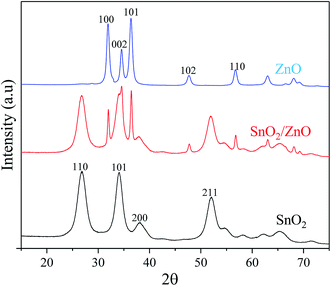 |
| | Fig. 1 XRD patterns of as-synthesized samples calcined at 500 °C. | |
The average crystallite size of the as-synthesized samples was calculated from the XRD line broadening measurement using the Debey–Scherrer's formula as follows:62
| |
D = (0.9λ)/(β![[thin space (1/6-em)]](https://www.rsc.org/images/entities/char_2009.gif) cos cos![[thin space (1/6-em)]](https://www.rsc.org/images/entities/char_2009.gif) θB) θB)
| (1) |
where
D is the average grain size,
λ is the wavelength of Cu Kα radiation (
λ = 1.5405 Å),
β is the full width at half maximum (FWHM) for the diffraction peak under the consideration (radian) and
θ is the diffraction angle (°). The width of the diffraction peaks of pure SnO
2 (
Fig. 1c) was considerably broadened, indicating a small crystalline domain size. The crystallite size of SnO
2 powders determined from (110) crystalline plane using Debye–Scherrer's equation was about 4.40 nm. On the other hand, the diffraction peaks of ZnO (
Fig. 1a) were sharper indicating highly crystalline nature of ZnO nanoparticles. The mean size of the crystallite of ZnO corresponding to (101) diffraction peak was 14 nm which indicates that the ZnO is more easily crystallized on calcination and consequently tends to have large grain size than that of SnO
2. The average size of the crystallite of ZnO (18.75 nm) in SnO
2/ZnO was larger than that of pure ZnO. These results were agreed with the literature results that the addition of SnO
2 causes an increase in crystallite size of ZnO and that ZnO restrains the growth of SnO
2 crystal.
48,63
TEM analysis. The crystallite/particle size, the crystallinity and the morphology of the as-synthesized samples prepared by polyol method were further examined by TEM. Fig. 2 shows the TEM and HRTEM images of the SnO2/ZnO nanocomposite (with SnO2![[thin space (1/6-em)]](https://www.rsc.org/images/entities/char_2009.gif) :
:![[thin space (1/6-em)]](https://www.rsc.org/images/entities/char_2009.gif) ZnO molar ration 1
ZnO molar ration 1![[thin space (1/6-em)]](https://www.rsc.org/images/entities/char_2009.gif) :
:![[thin space (1/6-em)]](https://www.rsc.org/images/entities/char_2009.gif) 1). As observed in TEM image (Fig. 2A), the shapes of SnO2 and ZnO in SnO2/ZnO nanocomposite are spherical and SnO2/ZnO nanocomposite is composed of aggregated ZnO and SnO2 nanoparticles, the size of ZnO being larger than that of SnO2. These results were in good agreement with results obtained from XRD analysis. A large number of small pores were also observed between the nanoparticles implying mesoporous SnO2/ZnO heterostructures. The lattice plane fringes of the SnO2 and ZnO nanoparticles were used to calculate the d-spacing values, and they were compared with those of bulk SnO2 and ZnO, indicating the formation of SnO2 and ZnO nanocrystals. As observed in Fig. 2B, the distances between the two lattice planes for SnO2/ZnO nanoparticles were around 0.33 and 0.27 nm, which correspond to the d-spacing of the (110) plane of tetragonal SnO2 and the (100) plane expected for the hexagonal wurtzite ZnO, respectively.
1). As observed in TEM image (Fig. 2A), the shapes of SnO2 and ZnO in SnO2/ZnO nanocomposite are spherical and SnO2/ZnO nanocomposite is composed of aggregated ZnO and SnO2 nanoparticles, the size of ZnO being larger than that of SnO2. These results were in good agreement with results obtained from XRD analysis. A large number of small pores were also observed between the nanoparticles implying mesoporous SnO2/ZnO heterostructures. The lattice plane fringes of the SnO2 and ZnO nanoparticles were used to calculate the d-spacing values, and they were compared with those of bulk SnO2 and ZnO, indicating the formation of SnO2 and ZnO nanocrystals. As observed in Fig. 2B, the distances between the two lattice planes for SnO2/ZnO nanoparticles were around 0.33 and 0.27 nm, which correspond to the d-spacing of the (110) plane of tetragonal SnO2 and the (100) plane expected for the hexagonal wurtzite ZnO, respectively.
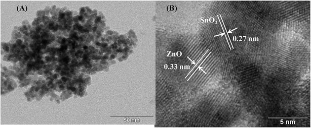 |
| | Fig. 2 (A) TEM image and (B) HRTEM image of SnO2/ZnO nanocomposite. | |
N2 adsorption–desorption analysis. N2 adsorption–desorption measurements at liquid N2 temperature (77 K) were conducted to determine the specific surface area and the pore size distribution of the as-synthesized ZnO, SnO2 and SnO2/ZnO nanoparticles. The N2 adsorption–desorption isotherms of the SnO2/ZnO nanocomposite shown in Fig. 3A exhibited a type IV curve accompanied by a type H2 hysteresis loop, indicating typical mesoporous materials according to the IUPAC classification. The H2-hysteresis loop also designated the presence of pores of nonuniform sizes and shapes, characteristic of solids consisting of particles crossed by nearly cylindrical channels or made by aggregates (consolidated) or agglomerates (unconsolidated) of spheroidal particles.64 Similar isotherms were observed for ZnO and SnO2 shown in Fig. S1.†
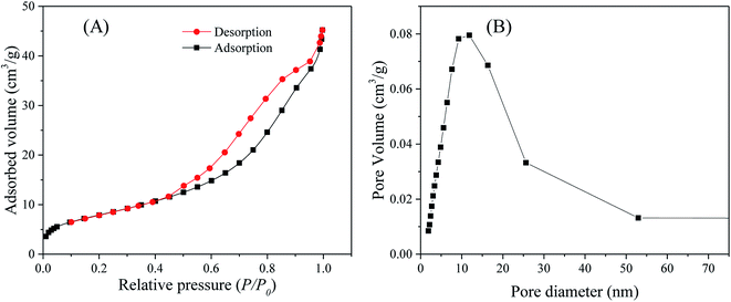 |
| | Fig. 3 (A) Nitrogen adsorption–desorption isotherms and (B) pore-size distribution of the SnO2/ZnO photocatalyst. | |
The textural properties, namely BET surface area, mean pore diameter and total pore volume of as-synthesized ZnO, SnO2 and SnO2/ZnO nanoparticles are given for comparison in Table 1. The ZnO photocatalyst possessed BET surface area of 22.5 m2 g−1 with mean pore diameter and total pore volume of 14 nm (within mesopore region) and 0.14 cm3 g−1, respectively. On the other hand, the BET surface area and mean pore diameter of SnO2 were found to be 52.1 m2 g−1 and 6.9 nm, respectively.
Table 1 Nitrogen sorption porosimetry studies of the as-synthesized SnO2, ZnO and SnO2/ZnO nanomaterials
| Samples |
BET surface area, m2 g−1 |
Mean pore diameter, nm |
Total pore volume, cm3 g−1 |
| ZnO |
22.5 |
14.0 |
0.14 |
| SnO2/ZnO |
30.0 |
8.8 |
0.06 |
| SnO2 |
52.1 |
6.9 |
0.10 |
The mesoporous SnO2/ZnO nanocomposites exhibited lower BET surface area than that of SnO2 nanoparticles. The SnO2/ZnO nanocomposites possessed BET surface area of 30 m2 g−1 and total volume of pores less than 193 nm diameter at P/P0 = 0.99 of 0.068 cm3 g−1. The pore size distribution of SnO2/ZnO nanocomposites (BJH model applied to the adsorption branch of the sorption isotherm) was rather large, i.e. from 2 to 50 nm, with an adsorption average pore diameter of 8.8 nm (Fig. 3B).
XPS analysis. To investigate the chemical composition and the chemical state of the elementals of SnO2/ZnO nanocomposites, XPS study was conducted and the results are shown in Fig. 4. The survey spectra of SnO2/ZnO in Fig. 4A only shows the emissions of Sn, Zn and O with very weak emission line of C and no peaks of other elements were observed. The C signal can be attributed to the adventitious carbon-based contaminant which commonly exists for XPS. The survey spectra exhibited the emission lines of Sn 3d, Sn 3p, Sn 4d, Zn 2p, Zn 3s, and Zn 3p core levels and the auger peaks of Sn MNN, Zn LMM and O KLL. The high-resolution spectra of Zn, Sn, and O species are shown in Fig. 4B–D, respectively. For pure ZnO, the emission lines appearing in Fig. 4B were symmetric and centered at 1021.49 and 1044.59 eV, which were attributed to Zn 2p3/2 and Zn 2p1/2, respectively. Thus, it could be confirmed that Zn element existed mainly as the form of Zn2+ chemical states in the as-prepared samples.65 The Zn 2p spectra of SnO2/ZnO shown in Fig. 4B demonstrated two emission lines, Zn 2p3/2 emission line centred at 1021.4 eV and Zn 2p1/2 line centred at 1044.5 eV.
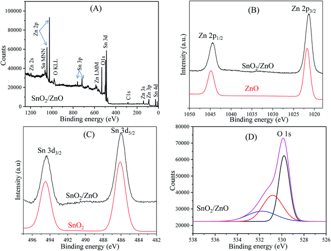 |
| | Fig. 4 XPS spectra of as-synthesized nanoparticles; (A) XPS survey spectra of SnO2/ZnO sample, (B) Zn 2p region, (C) Sn 3d region and (D) O 1s region. | |
Both the emission lines were symmetric and the binding energy difference (23.1 eV) between the two peaks was in good agreement with the standard reference value of ZnO.66 The estimated values of binding energies and the binding energy difference of the Zn 2p spectra confirmed the +2 oxidation state of Zn ions in SnO2/ZnO nanocomposites.66,67 The Zn 2p peaks of SnO2/ZnO were shifted towards lower binding energy. It was found that Zn 2p peaks were shifted to lower binding energies by 0.1 eV from their original values which were likely due to the charge transfer at the interface of SnO2/ZnO at thermal equilibrium. Fig. 4C shows the pronounced splitting of the Sn 3d emission into two symmetric peaks. The high resolution XPS spectra for Sn 3d of SnO2 demonstrated the spin orbital splitting of the Sn 3d5/2 and Sn 3d3/2 core level states of tin centred at 486.3 and 494.7 eV, respectively, which were symmetric and were assigned to the lattice tin oxide. The Sn 3d peaks of SnO2/ZnO centred at 486.1 eV was attributed to Sn 3d5/2 and the other one at 494.4 eV to Sn 3d3/2, indicating a normal oxidation state of Sn4+ in SnO2.68 The shape of high resolution XPS spectrum of O 1s was asymmetric and broad exhibiting multi-component oxygen species in the as prepared sample (Fig. 4D). The O 1s peak could bed de-convoluted into three symmetrical peaks centred at 529.79, 530.80, and 531.77 eV. The first peak at 529.79 eV was attributed to the lattice oxygen in Sn–O–Sn.69,70 The second peak at 530.80 eV was assigned to the lattice oxygen of ZnO.71 The higher binding energy at 531.8 eV was attributed to the chemisorbed oxygen on the surface of SnO2/ZnO.72
UV-vis DRS analysis. The optical absorption property of as-synthesized nanoparticles was examined by UV-vis DRS. When a semiconductor absorbs photons of energy larger than the band gap of the semiconductor, an electron is transferred from the valence band to the conduction band where there occurs an abrupt increase in the absorbency of the material to the wavelength corresponding to the band gap energy. The UV-vis DRS spectra of the as-synthesized samples are shown in Fig. 5A.
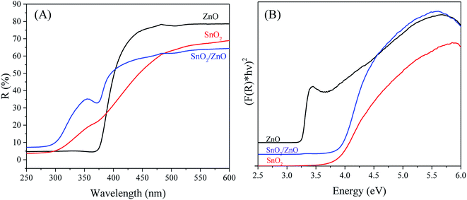 |
| | Fig. 5 UV-vis diffuse reflectance spectra (A) and plots of (F(R)hν)2 versus photon energy (hν) (B) of SnO2/ZnO sample calcined at 500 °C. | |
The pure SnO2 and ZnO exhibited the characteristic spectra of SnO2 and ZnO with their fundamental sharp absorption edges around 340 nm and 381 nm, respectively. The SnO2/ZnO nanocomposite showed two absorption edges, at 385 nm ascribed to ZnO and at 345 nm attributed to SnO2. Considering direct band gap semiconductor, the band gap energies (Eg) of as-synthesized nanoparticles were calculated from the following equation: α(hν) = A(hν − Eg)1/2 where α, ν, Eg, and A are the absorption coefficient, light frequency, band gap energy, and a constant, respectively.73 The energy band gap was estimated by extrapolating a straight line to the abscissa axis, where α is zero, for Eg = hν.74 It is generally admitted that the absorption coefficient (α) can be replaced by the remission function F(R). The later can be written in terms of diffused reflectance (R) according to the Kubelka–Munk theory: α/s = F(R) = (1R)2/(2R) where s is scattering coefficient.75 The band gap energies (Eg values) of the as-synthesized samples can thus be estimated from a plot of (F(R)hν)2 versus (hν) (Fig. 5B), the intercepts of the tangents yielding the band gap energies of the as-synthesized samples. The calculated band gap energies of ZnO, SnO2 and SnO2/ZnO were found to be 3.25, 3.7 and 3.65 eV from the extrapolation of the corresponding plot.
Photocatalytic performance evaluation. To evidence the photocatalytic performance of SnO2/ZnO nanomaterials, photocatalytic degradations of methylene blue (MB) were carried out as a test reaction under UV light irradiation. The time-dependent UV-vis spectra of MB during the UV light irradiation are illustrated in Fig. 6A. As depicted in Fig. 6A the maximum absorption peaks of MB at 664 nm diminished gradually and disappeared completely under UV light irradiation for 50 min in the presence of the SnO2/ZnO nanomaterials. Meanwhile, the color of the solution changed gradually with time as well, suggesting that the chromophoric structure of MB was decomposed (Fig. 6B). Furthermore, blank experiments in the presence of UV light irradiation without photocatalysts were carried out to rationalize the photocatalytic activity of the as-synthesized SnO2/ZnO photocatalysts.
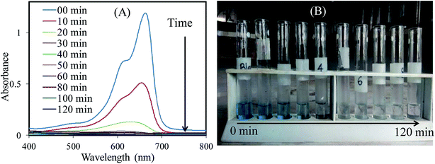 |
| | Fig. 6 Change in (A) absorbance and (B) color of MB solution with time under UV light irradiation in the presence of SnO2/ZnO nanocomposite. | |
In addition, the photocatalytic performance of pure SnO2, ZnO and commercial TiO2 (P25) were investigated as reference in order to compare the photocatalytic activity of SnO2/ZnO nanocomposite. All the photocatalytic experiments were carried out under identical condition. The degradation efficiency was defined as C/C0, where C0 and C are the initial concentration after equilibrium adsorption and the concentration of MB at any time, respectively. The photocatalytic performances of different photocatalysts are presented in Fig. 7. It is obvious from Fig. 7A that MB was not decomposed under only UV light irradiation in the absence of photocatalysts. In contrast, SnO2/ZnO nanocomposite (with molar ratio 1![[thin space (1/6-em)]](https://www.rsc.org/images/entities/char_2009.gif) :
:![[thin space (1/6-em)]](https://www.rsc.org/images/entities/char_2009.gif) 1) exhibited higher photocatalytic degradation efficiency than that of the pure SnO2, ZnO and P25. The efficiencies of SnO2, ZnO and P25 for the photocatalytic degradation of MB were about 85, 68 and 75%, respectively, after 30 min UV light irradiation whereas the value of about 98% was achieved for SnO2/ZnO nanocomposite indicating faster photodegradation rate of MB with SnO2/ZnO photocatalysts. To get into insight of the photocatalytic efficiency of the as-synthesized SnO2/ZnO nanocomposite, the kinetic analysis of MB degradation was discussed. It is well accepted that the photocatalytic decomposition of organic pollutants accords with a pseudo first-order kinetic rate law: ln(C/C0) = −kt, where k is degradation rate constant. A plot of ln
1) exhibited higher photocatalytic degradation efficiency than that of the pure SnO2, ZnO and P25. The efficiencies of SnO2, ZnO and P25 for the photocatalytic degradation of MB were about 85, 68 and 75%, respectively, after 30 min UV light irradiation whereas the value of about 98% was achieved for SnO2/ZnO nanocomposite indicating faster photodegradation rate of MB with SnO2/ZnO photocatalysts. To get into insight of the photocatalytic efficiency of the as-synthesized SnO2/ZnO nanocomposite, the kinetic analysis of MB degradation was discussed. It is well accepted that the photocatalytic decomposition of organic pollutants accords with a pseudo first-order kinetic rate law: ln(C/C0) = −kt, where k is degradation rate constant. A plot of ln![[thin space (1/6-em)]](https://www.rsc.org/images/entities/char_2009.gif) C/C0 against reaction time t yields a straight line whose slope gives reaction rate constant, k. Fig. 7B shows the plots of ln(C/C0) against t for different as-synthesized photocatalysts for the degradation of MB. As revealed in the Fig. 7B, the photocatalytic decomposition of MB followed pseudo-first order rate law and the SnO2/ZnO nanocomposite had a higher photocatalytic activity than the pure SnO2, ZnO and P25 nanoparticles, as evidenced by the larger value of k. The SnO2/ZnO nanocomposite showed the highest photocatalytic activity with a degradation rate constant reaching 0.138 min−1for the degradation of MB, values 2.23, 4.31 and 3.14 times higher than those measured with SnO2, ZnO and commercial TiO2 P25, respectively.
C/C0 against reaction time t yields a straight line whose slope gives reaction rate constant, k. Fig. 7B shows the plots of ln(C/C0) against t for different as-synthesized photocatalysts for the degradation of MB. As revealed in the Fig. 7B, the photocatalytic decomposition of MB followed pseudo-first order rate law and the SnO2/ZnO nanocomposite had a higher photocatalytic activity than the pure SnO2, ZnO and P25 nanoparticles, as evidenced by the larger value of k. The SnO2/ZnO nanocomposite showed the highest photocatalytic activity with a degradation rate constant reaching 0.138 min−1for the degradation of MB, values 2.23, 4.31 and 3.14 times higher than those measured with SnO2, ZnO and commercial TiO2 P25, respectively.
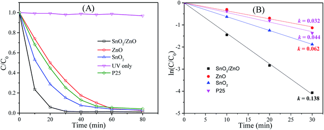 |
| | Fig. 7 (A) Photocatalytic degradation efficiencies of MB in presence of different photocatalysts under UV light irradiation, (B) kinetics of MB photocatalytic degradation (ln(C0/Ct) versus irradiation time). | |
The stability and reusability of the catalysts were evaluated by using the catalyst for three successive times. Fig. 8 shows the repetitive photodegradation of MB during three consecutive cycles. After each cycle, the SnO2/ZnO nanocomposites was separated by centrifugation and washed with double distilled water and subsequently a fresh solution of MB was added before to prepare solution for the following runs. Thus, the photocatalytic efficiencies for the 3 cycling reuse were 98%, 97% and 93% after 30 min of reaction time, respectively. No significant change in the catalytic efficiency for the degradation of MB evidenced the stability and reusability of the catalysts. The structure stability of the SnO2/ZnO photocatalyst after repeating photocatalytic tests was further confirmed by XRD analysis (Fig. S2†). According to Fig. S2,† all the diffraction peak lines of the used SnO2/ZnO photocatalyst was in good agreement with that of fresh SnO2/ZnO photocatalyst (Fig. 1) which demonstrated that the SnO2/ZnO photocatalyst was stable after successive use.
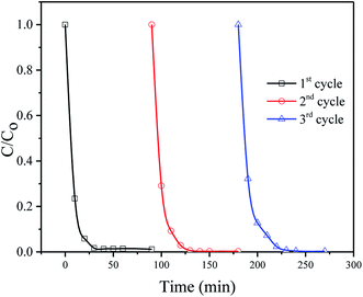 |
| | Fig. 8 Cyclic runs in the photodegradation of MB using the SnO2/ZnO photocatalyst under UV-light irradiation. | |
It is well known that the activity of photocatalyst depends on many factors such as textural properties as BET specific areas, average pore size and the recombination of the photogenerated electron–hole.76 The BET specific areas of SnO2, ZnO and SnO2/ZnO were found to be 45.1, 31 and 22.5 m2 g−1, respectively. It is reported that BET specific area of P25 is around 45 m2 g−1.77,78 Thus, the higher photocatalytic activity of SnO2 than that of commercial P25 could be rationalized on the basis of the increased BET specific area. The improved photocatalytic activity might also arise from the coupling of semiconductors with different band gap favoring the electron–hole charge separation resulting from band offsets. As a consequence, the enhanced photocatalytic activity found for the SnO2/ZnO heterostructure can be rationalized on the basis of the band alignment. In this context, the band-edge potential levels of the constituent semiconductors played a crucial role in determining direction of the flow of photoexcited charge carriers in the coupled semiconductors. It is reported that the conduction band (CB) edges of ZnO and SnO2 are situated −0.2 eV and 0.00 eV, respectively, while the valence band (VB) edges of ZnO and SnO2 are situated at 3.00 eV and 3.67 eV, respectively.79,80 Therefore, the conduction band and valence position of ZnO is higher (more negative) than the corresponding conduction and valence band position of SnO2.45,46 Consequently, there exist conduction and valence band offsets by 0.2 eV and 0.67 eV, respectively, at the interface of heterostructured ZnO/SnO2 nanocomposite. Recently, band alignment of ZnO/SnO2 nanocomposite has been studied and conduction and valence band offsets were found to be 0.20 eV and 0.70 eV, respectively.48 The conduction band (CB) edge and valence band (VB) edge of ZnO and SnO2 can be calculated by Mulliken electronegativity equation as below:81
where
χ is the electronegativity of the semiconductor,
EVB is the valance band edge potential,
ECB is the conduction band edge potential and
Eg is the band gap energy of the semiconductor. The estimated band gap energy of ZnO and SnO
2 were found to be 3.25 and 3.7 eV, respectively.
Ee is the energy of free electrons on the hydrogen scale (4.5 eV). The
χ is 5.79 and 6.25 eV for of ZnO and SnO2, respectively.
81,82 The estimated CB and VB edges of ZnO were found to be −0.3 eV and 2.92 eV, and of SnO
2 were −0.10 eV and 3.6 eV, respectively. Based on this calculation and considering the flat band potentials, the band alignment of ZnO/SnO
2 nanocomposite was proposed as in
Fig. 9. As seen in
Fig. 9, there exist energy gradient at the interface that tends to spatially separate electrons and holes on the different sides of the heterojunctions, where electrons may be confined to SnO
2 and holes to ZnO. The charge separation mechanism of heterostructure SnO
2/ZnO photocatalysts is also schematically described in
Fig. 9. When heterostructure ZnO/SnO
2 photocatalyst was irradiated with UV light, electrons in the valence band (VB) were excited to the conduction band (CB) of both oxides with the concomitant generation of the same number of holes in the valence band. Photogenerated electrons were then injected from the energetically higher CB edge ZnO to the lower CB edge SnO
2. Simultaneously, holes were injected in the opposite direction due to appropriate valence band offsets. Thus, photogenerated electrons and holes were vectorially transferred to SnO
2 and ZnO, respectively, suggesting efficient charge separation and reduction of charge recombination. The efficient charge separation also increased the lifetime of the charge carriers and enhanced the efficiency of the interfacial charge transfer to adsorbed organic pollutants accounting for the higher photocatalytic activity of the SnO
2/ZnO nanocomposites.
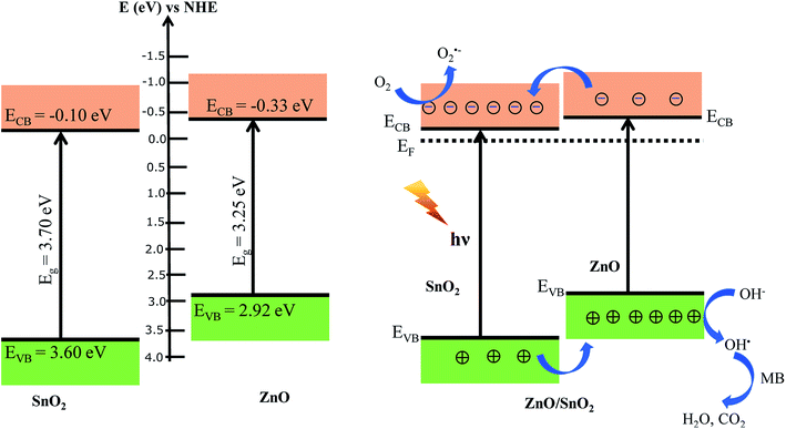 |
| | Fig. 9 Proposed schematic representation of band positions and the charge transfer process for the heterostructure SnO2/ZnO photocatalyst. | |
The photocatalytic reaction process can be proposed as follows
| SnO2/ZnO + hν → e−(SnO2) + h+(ZnO) |
| OH˙ + MB → degradation products |
The electrons in the conduction band of SnO2 react with molecular oxygen adsorbed on the surface of SnO2 to generate superoxide radials anion (O2˙−). The O2˙− radicals further react with H2O to produce OH˙ radicals. On the other hand, holes migrated to ZnO react with surface-bound hydroxyl groups (or H2O) to produce the hydroxyl radical species (OH˙) which is an extremely strong oxidant for the mineralization of organic chemicals as MB to degradation products like H2O and CO2.
COD analysis. The photocatalytic degradation of MB under UV light irradiation changes the solution to a colorless solution. The ultimate products of photocatalytic degradation of organic compound are CO2 and H2O. But visualization of color change does not indicate the formation of CO2 and H2O. Breaking of chromophore group of organic compounds by photodegradation can generate low molecular weight colorless organic compounds. The presence of low molecular weight compounds resulting from the photocatalytic degradation of MB can be evidenced by COD analysis. According to the Fig. 10, the COD value of MB solution before UV irradiation was about 24 mg L−1. In contrast, no COD value of the same sample was observed after photocatalytic degradation which indicated that the MB was completely mineralized to CO2 and H2O by the photocatalytic degradation with the as-prepared photocatalyst.
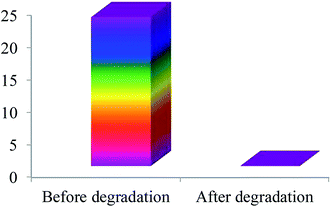 |
| | Fig. 10 COD values of MB before and after photocatalytic degradation with SnO2/ZnO nanocomposite. | |
Conclusion
The heterostructure ZnO/SnO2 nanocomposites have been successfully prepared by polyol method. The structural, morphological, optical, electrical, and photocatalytic performances of as-synthesized samples were evaluated. This heterojunction photocatalyst showed higher photocatalytic activity than the pure SnO2, ZnO and reference commercial TiO2 (P25) for the degradation of MB dye under UV light irradiation. The higher photocatalytic activity of SnO2/ZnO nanocomposites was mainly attributed to improved separation of photogenerated electrons and holes resulting from band offsets developed at the interface of SnO2/ZnO nanocomposites. Furthermore, the heterostructure SnO2/ZnO photocatalysts could be easily recycled without scarifying catalytic activity which evidenced the stability of the catalysts and the reproducibility of the approach. This concept of semiconducting heterojunction nanocatalysts with improved photocatalytic activity should find industrial application in the future to wastewater treatment technologies as well as to remove undesirable organics from the environment.
Conflicts of interest
On behalf of all authors, the corresponding author declares that there is no conflict of interest.
Acknowledgements
We gratefully acknowledge the support of the work by Shahjalal University of Science and Technology (SUST) Research Centre (Grant No.: AS/2017/15).
References
- V. K. Garg, R. Kumar and R. Gupta, Dyes Pigm., 2004, 62(1), 1–10, DOI:10.1016/j.dyepig.2003.10.016.
- P. A. Carneiro, R. F. P. Nogueira and M. V. B. Zanoni, Dyes Pigm., 2007, 74, 127–132, DOI:10.1016/j.dyepig.2006.01.022.
- A. Al-Kdasi, A. Idris, K. Saed and C. T. Guan, Global NEST J., 2004, 6, 222–230, DOI:10.30955/gnj.000288.
- S. Şen and G. N. Demirer, Water Res., 2003, 37, 1868–1878, DOI:10.1016/S0043-1354(02)00577-8.
- H. Ben Mansour, I. Houas, F. Montassar, K. Ghedira, D. Barillier, R. Mosrati and L. Chekir-Ghedira, Environ. Sci. Pollut. Res., 2012, 19, 2634–2643, DOI:10.1007/s11356-012-0802-7.
- W. Przystas, E. Zablocka-Godlewska and E. Grabinska-Sota, Water, Air, Soil Pollut., 2012, 223, 1581–1592, DOI:10.1007/s11270-011-0966-7.
- P. A. Carneiro, G. A. Umbuzeiro, D. P. Oliveira and M. V. B. Zanoni, J. Hazard. Mater., 2010, 174, 694–699, DOI:10.1016/j.jhazmat.2009.09.106.
- I. Jäger, C. Hafner and K. Schneider, Mutat. Res., Genet. Toxicol. Environ. Mutagen., 2004, 561, 35–44, DOI:10.1016/j.mrgentox.2004.03.005.
- F. M. D. Chequer, T. M. Lizier, R. de Felício, M. V. B. Zanoni, H. M. Debonsi, N. P. Lopes, R. Marcos and D. P. de Oliveira, Toxicol. In Vitro, 2011, 25, 2054–2063, DOI:10.1016/j.tiv.2011.05.033.
- E. R. A. Ferraz, G. A. Umbuzeiro, G. de-Almeida, A. Caloto-Oliveira, F. M. D. Chequer, M. V. B. Zanoni, D. J. Dorta and D. P. Oliveira, Environ. Toxicol., 2011, 26, 489–497, DOI:10.1002/tox.20576.
- I. Oller, S. Malato and J. A. Sánchez-Pérez, Sci. Total Environ., 2011, 409, 4141–4166, DOI:10.1016/j.scitotenv.2010.08.061.
- K. Paździor, L. Bilińska and S. Ledakowicz, Chem. Eng. J., 2019, 376, 120597, DOI:10.1016/j.cej.2018.12.057.
- M. C. Collivignarelli, A. Abbà, M. Carnevale Miino and S. Damiani, J. Environ. Manage., 2019, 236, 727–745, DOI:10.1016/j.jenvman.2018.11.094.
- U. I. Gaya and A. H. Abdullah, J. Photochem. Photobiol., C, 2008, 9, 1–12, DOI:10.1016/j.jphotochemrev.2007.12.003.
- A. Buthiyappan, A. A. Abdul Raman and W. M. A. W. Daud, RSC Adv., 2016, 30, 25222–25241, 10.1039/c5ra26775g.
- J. P. Guin, D. B. Naik, Y. K. Bhardwaj and L. Varshney, RSC Adv., 2014, 4, 39941–39947, 10.1039/c4ra00884g.
- E. E. Ebrahiem, M. N. Al-Maghrabi and A. R. Mobarki, Arabian J. Chem., 2016, 10, S1674–S1679, DOI:10.1016/j.arabjc.2013.06.012.
- M. Bartolomeu, M. G. P. M. S. Neves, M. A. F. Faustino and A. Almeida, Photochem. Photobiol. Sci., 2018, 17, 1573–1598, 10.1039/c8pp00249e.
- S. S. Muniandy, N. H. Mohd Kaus, Z. T. Jiang, M. Altarawneh and H. L. Lee, RSC Adv., 2017, 7, 48083–48094, 10.1039/c7ra08187a.
- G. Song, C. Luo, Q. Fu and C. Pan, RSC Adv., 2016, 6, 84035–84041, 10.1039/c6ra17665h.
- F. Ahmed, N. Arshi, M. S. Anwar, R. Danish and B. H. Koo, RSC Adv., 2014, 4, 29249–29263, 10.1039/c4ra02470b.
- S. Adhikari, D. Sarkar and G. Madras, RSC Adv., 2014, 4, 55807–55814, 10.1039/c4ra09376c.
- T. K. Le, T. M. T. Nguyen, H. T. P. Nguyen, T. K. L. Nguyen, T. Lund, H. K. H. Nguyen and T. K. X. Huynh, Arabian J. Chem., 2020, 13, 1032–1039, DOI:10.1016/j.arabjc.2017.09.006.
- J. T. Park, C. S. Lee and J. H. Kim, RSC Adv., 2014, 4, 31452–31461, 10.1039/c4ra03949a.
- M. T. Uddin, Y. Sultana and M. A. Islam, J. Sci. Res., 2016, 8, 399–411, DOI:10.3329/jsr.v8i3.27524.
- A. Kolodziejczak-Radzimska and T. Jesionowski, Materials, 2014, 7, 2833–2881, DOI:10.3390/ma7042833.
- M. T. Uddin, Y. Nicolas, C. Olivier, L. Servant, T. Toupance, S. Li, A. Klein and W. Jaegermann, Phys. Chem. Chem. Phys., 2015, 17, 5090–5102, 10.1039/c4cp04780j.
- S. K. Kansal, N. Kaur and S. Singh, Nanoscale Res. Lett., 2009, 4, 709–716, DOI:10.1007/s11671-009-9300-3.
- A. Khani, Desalin. Water Treat., 2017, 62, 426–430, DOI:10.5004/dwt.2017.0119.
- Q. Zhang, X. Zhao, L. Duan, H. Shen and R. Liu, J. Photochem. Photobiol., A, 2020, 392, 112156, DOI:10.1016/j.jphotochem.2019.112156.
- Y. Chen, L. Wang, R. Gao, Y. C. Zhang, L. Pan, C. Huang, K. Liu, X. Y. Chang, X. Zhang and J. J. Zou, Appl. Catal., B, 2019, 259, 118079, DOI:10.1016/j.apcatb.2019.118079.
- H. Zhang, M. Ying, R. Gao, L. Hu, Z. Jiao and X. Zhu, RSC Adv., 2015, 5, 58439–58448, 10.1039/c5ra08919k.
- K. Rajkumar, P. Vairaselvi, P. Saravanan, V. T. P. Vinod, M. Černík and R. T. Rajendra Kumar, RSC Adv., 2015, 5, 20424–20431, 10.1039/c4ra13434f.
- W. A. Thompson, A. Olivo, D. Zanardo, G. Cruciani, F. Menegazzo, M. Signoretto and M. M. Maroto-Valer, RSC Adv., 2019, 9, 21660–21666, 10.1039/c9ra03435h.
- F. A. M. Al-Zahrani, R. M. El-Shishtawy, N. S. E. Ahmed, N. S. Awwad, M. S. Hamdy and A. M. Asiri, Arabian J. Chem., 2020, 13, 3633–3638, DOI:10.1016/j.arabjc.2019.12.007.
- A. Khani and B. Pezeshki, Desalin. Water Treat., 2017, 57, 7047–7053, DOI:10.1080/19443994.2015.1012749.
- N. Ahmad, S. Sultana, S. M. Faisal, A. Ahmed, S. Sabir and M. Z. Khan, RSC Adv., 2019, 9, 41135–41150, 10.1039/c9ra06493a.
- X. Di, F. Guo, Z. Zhu, Z. Xu, Z. Qian and Q. Zhang, RSC Adv., 2019, 9, 41209–41217, 10.1039/c9ra09260a.
- S. Wang, C. Y. Huang, L. Pan, Y. Chen, X. Zhang, Fazal-e-Aleem and J. J. Zou, Catal. Today, 2019, 335, 151–159, DOI:10.1016/j.cattod.2018.10.059.
- S. Das and V. Jayaraman, Prog. Mater. Sci., 2014, 66, 112–255, DOI:10.1016/j.pmatsci.2014.06.003.
- J. S. Chen and X. W. Lou, Small, 2013, 9, 1877–1893, DOI:10.1002/smll.201202601.
- B. Kumar, V. Atla, J. P. Brian, S. Kumari, T. Q. Nguyen, M. Sunkara and J. M. Spurgeon, Angew. Chem., Int. Ed., 2017, 56, 3645–3649, DOI:10.1002/anie.201612194.
- Y. Cheng, K. S. Chen, N. L. Meyer, J. Yuan, L. S. Hirst, P. B. Chase and P. Xiong, Biosens. Bioelectron., 2011, 26, 4538–4544, DOI:10.1016/j.bios.2011.05.019.
- W. Zhou, Y. Liu, Y. Yang and P. Wu, J. Phys. Chem. C, 2014, 118, 6448–6453, DOI:10.1021/jp500546r.
- K. Vinodgopal and P. V. Kamat, Environ. Sci. Technol., 1995, 29, 841–845, DOI:10.1021/es00003a037.
- R. Daghrir, P. Drogui and D. Robert, Ind. Eng. Chem. Res., 2013, 52, 3581–3599 CrossRef CAS.
- L. Ren, D. Chen, Z. Hu, Z. Gao, Z. Luo, Z. Chen, Y. Jiang, B. Zhao, C. M. L. Wu and C. H. Shek, RSC Adv., 2016, 6, 82096–82102, 10.1039/c6ra19004a.
- M. T. Uddin, Y. Nicolas, C. Olivier, T. Toupance, L. Servant, M. M. Müller, H.-J. Kleebe, J. Ziegler and W. Jaegermann, Inorg. Chem., 2012, 51(14), 7764–7773, DOI:10.1021/ic300794j.
- Y. Yu, B. Yao, B. Cao and W. Ma, Photochem. Photobiol., 2019, 95, 1131–1141, DOI:10.1111/php.13101.
- S. Chen, F. Liu, M. Xu, J. Yan, F. Zhang, W. Zhao, Z. Zhang, Z. Deng, J. Yun, R. Chen and C. Liu, J. Colloid Interface Sci., 2019, 553, 613–621, DOI:10.1016/j.jcis.2019.06.053.
- S. Sehar, I. Naz, I. Perveen and S. Ahmed, Korean J. Chem. Eng., 2019, 36, 56–62, DOI:10.1007/s11814-018-0159-9.
- M. M. Rashad, A. A. Ismail, I. Osama, I. A. Ibrahim and A. H. T. Kandil, Arabian J. Chem., 2014, 7, 71–77, DOI:10.1016/j.arabjc.2013.08.016.
- Z. Yang, L. Lv, Y. Dai, Z. Xv and D. Qian, Appl. Surf. Sci., 2010, 256, 2898–2902, DOI:10.1016/j.apsusc.2009.11.047.
- V. Kuzhalosai, B. Subash, A. Senthilraja, P. Dhatshanamurthi and M. Shanthi, Spectrochim. Acta, Part A, 2013, 115, 876–882, DOI:10.1016/j.saa.2013.06.106.
- M. T. Uddin, Y. Nicolas, C. Olivier, T. Toupance, L. Servant, M. M. Müller, H. J. Kleebe, J. Ziegler and W. Jaegermann, Inorg. Chem., 2012, 51, 7764–7773, DOI:10.1021/ic300794j.
- A. Hamrouni, N. Moussa, F. Parrino, A. Di Paola, A. Houas and L. Palmisano, J. Mol. Catal. A: Chem., 2014, 390, 133–141, DOI:10.1016/j.molcata.2014.03.018.
- I. Das, S. Sagadevan, Z. Z. Chowdhury and M. E. Hoque, J. Mater. Sci.:
Mater. Electron., 2018, 29, 4128–4135, DOI:10.1007/s10854-017-8357-5.
- Z. Zhang, C. Shao, X. Li, L. Zhang, H. Xue, C. Wang and Y. Liu, J. Phys. Chem. C, 2010, 114, 7920–7925, DOI:10.1021/jp100262q.
- B. W. Chieng and Y. Y. Loo, Mater. Lett., 2012, 73, 78–82, DOI:10.1016/j.matlet.2012.01.004.
- S. Lee, S. Jeong, D. Kim, S. Hwang, M. Jeon and J. Moon, Superlattices Microstruct., 2008, 43, 330–339, DOI:10.1016/j.spmi.2008.01.004.
- R. Sasikala, A. Shirole, V. Sudarsan, T. Sakuntala, C. Sudakar, R. Naik and S. R. Bharadwaj, Int. J. Hydrogen Energy, 2009, 34, 3621–3630, DOI:10.1016/j.ijhydene.2009.02.085.
- A. L. Patterson, Phys. Rev., 1939, 56, 978–982, DOI:10.1103/PhysRev.56.978.
- W. Cun, Z. Jincai, W. Xinming, M. Bixian, S. Guoying, P. Ping’an and F. Jiamo, Appl. Catal., B, 2002, 39, 269–279, DOI:10.1016/S0926-3373(02)00115-7.
- G. Leofanti, M. Padovan, G. Tozzola and B. Venturelli, Catal. Today, 1998, 41, 207–219, DOI:10.1016/S0920-5861(98)00050-9.
- S. Bang, S. Lee, Y. Ko, J. Park, S. Shin, H. Seo and H. Jeon, Nanoscale Res. Lett., 2012, 7, 290, DOI:10.1186/1556-276X-7-290.
- G. E. Briggs, D. Wanger, C. D. Riggs, W. M. Davis, L. E. Moulder and J. F. Muilenberg, Handbook of X-ray Photoelectron Spectroscopy, Perkin-Elmer Corp., 1979 Search PubMed.
- S. Parthasarathy, V. Nandhini and B. G. Jeyaprakash, J. Colloid Interface Sci., 2016, 482, 81–88, DOI:10.1016/j.jcis.2016.07.066.
- J. F. Moulder, W. F. Stickle, P. E. Sobol and K. D. Bomben, Handbook of X-ray photoelectron spectroscopy: a reference book of standard spectra for identification and interpretation of XPS data, Perkin-Elmer Corp., 1992 Search PubMed.
- M. Kaur, N. S. Ramgir, U. K. Gautam, S. K. Ganapathi, S. Bhattacharya, N. Datta, V. Saxena, A. K. Debnath, D. K. Aswal and S. K. Gupta, Mater. Chem. Phys., 2014, 147, 707–714, DOI:10.1016/j.matchemphys.2014.06.010.
- H. Hu, L. Gui, W. Zhou, J. Sun, J. Xu, Q. Wang, B. He and L. Zhao, Electrochim. Acta, 2018, 285, 70–77, DOI:10.1016/j.electacta.2018.08.002.
- G. Ballerini, K. Ogle and M. G. Barthés-Labrousse, Appl. Surf. Sci., 2007, 253, 6860–6867, DOI:10.1016/j.apsusc.2007.01.126.
- X. Q. Pan and L. Fu, J. Appl. Phys., 2001, 89, 6048–6055, DOI:10.1063/1.1368865.
- E. A. Davis and N. F. Mott, Philos. Mag., 1970, 22, 0903–0922, DOI:10.1080/14786437008221061.
- E. Sanchez and T. Lopez, Mater. Lett., 1995, 25, 271–275, DOI:10.1016/0167-577X(95)00190-5.
- A. B. Murphy, Sol. Energy Mater. Sol. Cells, 2007, 91, 1326–1337, DOI:10.1016/j.solmat.2007.05.005.
- A. Bhattacharjee, M. Ahmaruzzaman and T. Sinha, Spectrochim. Acta, Part A, 2015, 136, 751–760, DOI:10.1016/j.saa.2014.09.092.
- G. Wang, L. Xu, J. Zhang, T. Yin and D. Han, Int. J. Photoenergy, 2012, 265760, DOI:10.1155/2012/265760.
- M. T. Uddin, Y. Nicolas, C. Olivier, T. Toupance, M. M. Müller, H.-J. Kleebe, K. Rachut, J. Ziegler, A. Klein and W. Jaegermann, J. Phys. Chem. C, 2013, 117, 22098–22110, DOI:10.1021/jp407539c.
- S. G. Kumar and L. G. Devi, J. Phys. Chem. A, 2011, 115, 13211–13241, DOI:10.1021/jp204364a.
- Y. Wang, Q. Wang, X. Zhan, F. Wang, M. Safdar and J. He, Nanoscale, 2013, 5, 8326–8339, 10.1039/C3NR01577G.
- X. Yong and M. A. A. Schoonen, Am. Mineral., 2000, 85, 543–556, DOI:10.2138/am-2000-0416.
- M. A. Butler, J. Electrochem. Soc., 1978, 125, 228–232, DOI:10.1149/1.2131419.
Footnote |
| † Electronic supplementary information (ESI) available. See DOI: 10.1039/d0ra03233f |
|
| This journal is © The Royal Society of Chemistry 2020 |
Click here to see how this site uses Cookies. View our privacy policy here.  Open Access Article
 *,
Md. Enamul Hoque and
Mitun Chandra Bhoumick
![[thin space (1/6-em)]](https://www.rsc.org/images/entities/char_2009.gif) :
:![[thin space (1/6-em)]](https://www.rsc.org/images/entities/char_2009.gif) Sn of 2
Sn of 2![[thin space (1/6-em)]](https://www.rsc.org/images/entities/char_2009.gif) :
:![[thin space (1/6-em)]](https://www.rsc.org/images/entities/char_2009.gif) 1 synthesised by co-precipitation method showed higher photocatalytic degradation of methyl orange (MO) than the individual ZnO and SnO2.53 Yu et al.49 synthesized SnO2/ZnO nanocomposites via hydrothermal technique followed by calcination in air that exhibited considerably higher degradation efficiency for the photodegradation of methylene blue and quinolone antibiotics under mercury lamp irradiation than pure ZnO and SnO2 analogues. A similar trend has also been observed by Zhang et al.58 for one-dimensional ZnO–SnO2 nanofibers synthesized by a simple combination method of sol–gel process and electrospinning technique. However, the nanoparticles synthesized by these approaches tend to agglomerate because of large specific surface area along with high surface energy. Recently, polyol-mediated synthesis has turned out to be well-suited for the preparation of metal oxide nanoparticles.59–61 The polyol method is a versatile liquid-phase method utilizing high boiling polyols such as ethylene glycol, diethylene glycol, tetraethylene glycol or glycerol to produce nanoparticles. Here, the polyol serves as a solvent and stabilizing agent that limits the growth of particles resulting suppression of particles agglomeration. Moreover, the synthesis is straightforward to carry out and requires neither multisequential steps nor advanced experimental condition or equipment. However, to the best of our knowledge, the synthesis of SnO2/ZnO nanoparticles by polyol method is yet to be reported. Therefore, in the present study we would like to present a detailed investigation on the preparation, characterization, and photocatalysis evaluation of heterostructure SnO2/ZnO synthesized by polyol method.
1 synthesised by co-precipitation method showed higher photocatalytic degradation of methyl orange (MO) than the individual ZnO and SnO2.53 Yu et al.49 synthesized SnO2/ZnO nanocomposites via hydrothermal technique followed by calcination in air that exhibited considerably higher degradation efficiency for the photodegradation of methylene blue and quinolone antibiotics under mercury lamp irradiation than pure ZnO and SnO2 analogues. A similar trend has also been observed by Zhang et al.58 for one-dimensional ZnO–SnO2 nanofibers synthesized by a simple combination method of sol–gel process and electrospinning technique. However, the nanoparticles synthesized by these approaches tend to agglomerate because of large specific surface area along with high surface energy. Recently, polyol-mediated synthesis has turned out to be well-suited for the preparation of metal oxide nanoparticles.59–61 The polyol method is a versatile liquid-phase method utilizing high boiling polyols such as ethylene glycol, diethylene glycol, tetraethylene glycol or glycerol to produce nanoparticles. Here, the polyol serves as a solvent and stabilizing agent that limits the growth of particles resulting suppression of particles agglomeration. Moreover, the synthesis is straightforward to carry out and requires neither multisequential steps nor advanced experimental condition or equipment. However, to the best of our knowledge, the synthesis of SnO2/ZnO nanoparticles by polyol method is yet to be reported. Therefore, in the present study we would like to present a detailed investigation on the preparation, characterization, and photocatalysis evaluation of heterostructure SnO2/ZnO synthesized by polyol method.![[thin space (1/6-em)]](https://www.rsc.org/images/entities/char_2009.gif) :
:![[thin space (1/6-em)]](https://www.rsc.org/images/entities/char_2009.gif) ZnO 1
ZnO 1![[thin space (1/6-em)]](https://www.rsc.org/images/entities/char_2009.gif) :
:![[thin space (1/6-em)]](https://www.rsc.org/images/entities/char_2009.gif) 1. Pure SnO2 and ZnO were synthesized by adopting similar procedure.
1. Pure SnO2 and ZnO were synthesized by adopting similar procedure.
![[thin space (1/6-em)]](https://www.rsc.org/images/entities/char_2009.gif) cos
cos![[thin space (1/6-em)]](https://www.rsc.org/images/entities/char_2009.gif) θB)
θB)
![[thin space (1/6-em)]](https://www.rsc.org/images/entities/char_2009.gif) :
:![[thin space (1/6-em)]](https://www.rsc.org/images/entities/char_2009.gif) ZnO molar ration 1
ZnO molar ration 1![[thin space (1/6-em)]](https://www.rsc.org/images/entities/char_2009.gif) :
:![[thin space (1/6-em)]](https://www.rsc.org/images/entities/char_2009.gif) 1). As observed in TEM image (Fig. 2A), the shapes of SnO2 and ZnO in SnO2/ZnO nanocomposite are spherical and SnO2/ZnO nanocomposite is composed of aggregated ZnO and SnO2 nanoparticles, the size of ZnO being larger than that of SnO2. These results were in good agreement with results obtained from XRD analysis. A large number of small pores were also observed between the nanoparticles implying mesoporous SnO2/ZnO heterostructures. The lattice plane fringes of the SnO2 and ZnO nanoparticles were used to calculate the d-spacing values, and they were compared with those of bulk SnO2 and ZnO, indicating the formation of SnO2 and ZnO nanocrystals. As observed in Fig. 2B, the distances between the two lattice planes for SnO2/ZnO nanoparticles were around 0.33 and 0.27 nm, which correspond to the d-spacing of the (110) plane of tetragonal SnO2 and the (100) plane expected for the hexagonal wurtzite ZnO, respectively.
1). As observed in TEM image (Fig. 2A), the shapes of SnO2 and ZnO in SnO2/ZnO nanocomposite are spherical and SnO2/ZnO nanocomposite is composed of aggregated ZnO and SnO2 nanoparticles, the size of ZnO being larger than that of SnO2. These results were in good agreement with results obtained from XRD analysis. A large number of small pores were also observed between the nanoparticles implying mesoporous SnO2/ZnO heterostructures. The lattice plane fringes of the SnO2 and ZnO nanoparticles were used to calculate the d-spacing values, and they were compared with those of bulk SnO2 and ZnO, indicating the formation of SnO2 and ZnO nanocrystals. As observed in Fig. 2B, the distances between the two lattice planes for SnO2/ZnO nanoparticles were around 0.33 and 0.27 nm, which correspond to the d-spacing of the (110) plane of tetragonal SnO2 and the (100) plane expected for the hexagonal wurtzite ZnO, respectively.


![[thin space (1/6-em)]](https://www.rsc.org/images/entities/char_2009.gif) :
:![[thin space (1/6-em)]](https://www.rsc.org/images/entities/char_2009.gif) 1) exhibited higher photocatalytic degradation efficiency than that of the pure SnO2, ZnO and P25. The efficiencies of SnO2, ZnO and P25 for the photocatalytic degradation of MB were about 85, 68 and 75%, respectively, after 30 min UV light irradiation whereas the value of about 98% was achieved for SnO2/ZnO nanocomposite indicating faster photodegradation rate of MB with SnO2/ZnO photocatalysts. To get into insight of the photocatalytic efficiency of the as-synthesized SnO2/ZnO nanocomposite, the kinetic analysis of MB degradation was discussed. It is well accepted that the photocatalytic decomposition of organic pollutants accords with a pseudo first-order kinetic rate law: ln(C/C0) = −kt, where k is degradation rate constant. A plot of ln
1) exhibited higher photocatalytic degradation efficiency than that of the pure SnO2, ZnO and P25. The efficiencies of SnO2, ZnO and P25 for the photocatalytic degradation of MB were about 85, 68 and 75%, respectively, after 30 min UV light irradiation whereas the value of about 98% was achieved for SnO2/ZnO nanocomposite indicating faster photodegradation rate of MB with SnO2/ZnO photocatalysts. To get into insight of the photocatalytic efficiency of the as-synthesized SnO2/ZnO nanocomposite, the kinetic analysis of MB degradation was discussed. It is well accepted that the photocatalytic decomposition of organic pollutants accords with a pseudo first-order kinetic rate law: ln(C/C0) = −kt, where k is degradation rate constant. A plot of ln![[thin space (1/6-em)]](https://www.rsc.org/images/entities/char_2009.gif) C/C0 against reaction time t yields a straight line whose slope gives reaction rate constant, k. Fig. 7B shows the plots of ln(C/C0) against t for different as-synthesized photocatalysts for the degradation of MB. As revealed in the Fig. 7B, the photocatalytic decomposition of MB followed pseudo-first order rate law and the SnO2/ZnO nanocomposite had a higher photocatalytic activity than the pure SnO2, ZnO and P25 nanoparticles, as evidenced by the larger value of k. The SnO2/ZnO nanocomposite showed the highest photocatalytic activity with a degradation rate constant reaching 0.138 min−1for the degradation of MB, values 2.23, 4.31 and 3.14 times higher than those measured with SnO2, ZnO and commercial TiO2 P25, respectively.
C/C0 against reaction time t yields a straight line whose slope gives reaction rate constant, k. Fig. 7B shows the plots of ln(C/C0) against t for different as-synthesized photocatalysts for the degradation of MB. As revealed in the Fig. 7B, the photocatalytic decomposition of MB followed pseudo-first order rate law and the SnO2/ZnO nanocomposite had a higher photocatalytic activity than the pure SnO2, ZnO and P25 nanoparticles, as evidenced by the larger value of k. The SnO2/ZnO nanocomposite showed the highest photocatalytic activity with a degradation rate constant reaching 0.138 min−1for the degradation of MB, values 2.23, 4.31 and 3.14 times higher than those measured with SnO2, ZnO and commercial TiO2 P25, respectively.


