
 Open Access Article
 This Open Access Article is licensed under a Creative Commons Attribution-Non Commercial 3.0 Unported Licence
The aging properties and phase morphology of silica filled silicone rubber/butadiene rubber composites
Lin Leng†
a,
Qing-Yuan Han†a and
You-Ping Wu *ab
*ab
aState Key Laboratory of Organic–Inorganic Composites, Beijing University of Chemical Technology, Beijing 100029, China. E-mail: wuyp@mail.buct.edu.cn; Fax: +86-10-64456158; Tel: +86-10-64442621
bBeijing Engineering Research Centre of Advanced Elastomers, Beijing University of Chemical Technology, Beijing 100029, China
First published on 27th May 2020
Abstract
Large amounts of antioxidants are used in unsaturated rubber composites, such as butadiene rubber (BR), which would inevitably cause surface discoloration. In this study, silicone rubber (VMQ) was blended with BR for improving its anti-aging properties. It was found that VMQ/BR exhibits better thermal oxidative aging and ozone aging resistance than BR, especially for 20/80 VMQ/BR. Atomic force microscopy (AFM) and transmission electron microscopy (TEM) were applied to characterize the phase morphology of VMQ–silica master-batch/BR, indicating that VMQ phases present island-dispersed domains of circular and elliptical shapes in the BR matrix, and silica particles mainly exist at the interface between BR and VMQ phases. These are two decisive factors for the improved aging properties of VMQ/BR.
Introduction
The microstructure of high cis-butadiene rubber (BR) is relatively regular with little side groups,1 and its molecular chains, with weak intermolecular forces, exhibit free internal rotation and high flexibility. Hence, among common synthetic rubbers, BR possesses excellent elasticity, low hysteresis, excellent wear resistance and eminent crack initiation resistance.2 Because of the good compatibility with elastomers like natural rubber (NR) and styrene-butadiene rubber (SBR),3 their blends are widely applied in tire treads and sidewalls.In order to improve aging resistance of BR, amine antioxidants are generally used,4 but would unavoidably cause the discoloration of tire surfaces.5,6 Moreover, blending is a usual method to increase cost-efficiency and combined performances that single component could not achieve, so saturated-backbone polymers like ethylene-propylene-diene rubber (EPDM) are often conducted to compound with BR.7–9
Silicone rubber (VMQ) has a highly saturated main chain, which composes of silicon and oxygen atoms alternatively, so its corresponding high and low temperature resistance, heat-resistance, oxidative and ozone aging resistance, chemical stability, weatherability and radiation resistance are excellent.10,11 In addition, due to the independence on ever-reducing petroleum sources, VMQ is energy-saving and environmental-friendly.12 However, because of the large differences in surface characteristic and saturating degree, it is quite difficult to blend saturated and low surface energy VMQ with unsaturated rubber of high surface energy, such as BR, SBR, NR. In our previous studies, VMQ/SBR blends were prepared, which focus on investigations of strengthening interfacial compatibility13 and rubber–filler interaction;14 besides, dynamic fatigue crack propagation behaviour of VMQ/NR composites was also studied.15
Here, VMQ was applied to improve anti-aging properties of BR, further to reduce the dosage of antioxidants and prevent product surface discoloration. As for microscopic morphology would greatly influence macroscopic properties of composites, the two-phase structure of VMQ–silica master-batch/BR and distribution of filler were further investigated via atomic force microscopy (AFM) and transmission electron microscopy (TEM). The results could provide guidance for better understanding of VMQ/BR composites.
Experimental
Materials
Commercial butadiene rubber (BR CB22, neodymium-based) was obtained from Lanxess Co., Ltd. (Germany). Commercial methyl-vinyl-silicone rubber (VMQ 110-9, Mn = 4.5 × 10⁵, vinyl content = 5 wt%) was purchased from Daoruo Silicon Industry Co., Ltd. (Ningbo, China). Precipitated silica (Ultrasil VN3), was provided by Evonik Degussa Co., Ltd. (Qingdao, China). Silane coupling agent Si69 (bis-[γ-(triethoxy silicon)-propyl] tetrasulfide), was purchased from Shuguang chemical Co., Ltd. (Nanjing, China). Silane coupling agent A-151 (CH2![[double bond, length as m-dash]](https://www.rsc.org/images/entities/char_e001.gif) CHSi(OC2H5)3) was provided by Chenguang Chemical Industry Co., Ltd. (Shandong, China). Peroxide curing agent DBPMH (2,5-dimethyl-2,5-di(tert-butylperoxy)-hexane) was purchased from AkzoNobel Co., Ltd. (Jiangsu, China). Antioxidant 4010NA (N-isopropyl-N′-phenyl-p-phenylenediamine) was provided by Sam chemical technology Co., Ltd. (Shanghai, China). The other ingredients, such as hydroxyl silicone oil, were all commercially available industrial products.
CHSi(OC2H5)3) was provided by Chenguang Chemical Industry Co., Ltd. (Shandong, China). Peroxide curing agent DBPMH (2,5-dimethyl-2,5-di(tert-butylperoxy)-hexane) was purchased from AkzoNobel Co., Ltd. (Jiangsu, China). Antioxidant 4010NA (N-isopropyl-N′-phenyl-p-phenylenediamine) was provided by Sam chemical technology Co., Ltd. (Shanghai, China). The other ingredients, such as hydroxyl silicone oil, were all commercially available industrial products.
Preparation of VMQ/BR composites
In order to match the big viscosity gap between VMQ and BR, VMQ–silica master-batch was prepared firstly refer to our previous study,13 with feeding ratio of VMQ![[thin space (1/6-em)]](https://www.rsc.org/images/entities/char_2009.gif) :silica:A-151:hydroxyl silicone oil = 100:35:3:1, conducted on a two-roll mill (X(S)K-160, Shanghai rubber machinery Co., Ltd., China) at room temperature. The hydroxyl silicone oil is used to prevent networking of silica particles in VMQ matrix.
:silica:A-151:hydroxyl silicone oil = 100:35:3:1, conducted on a two-roll mill (X(S)K-160, Shanghai rubber machinery Co., Ltd., China) at room temperature. The hydroxyl silicone oil is used to prevent networking of silica particles in VMQ matrix.
The formula of VMQ/BR compounds is shown in Table 1, a three-step process was adopted. First, BR, VMQ–silica master-batch, silica and Si69 were mixed together on the two-roll mill at room temperature. Next, the first-step compound was added into internal mixer (RM-200C, Hapro electric technology Co., Ltd., Harbin, China) at 145 °C for heat treatment of 5 min, and antioxidant 4010NA was mixed for another 1 min. Last, the second-step compound was cooled to room temperature, and curing agent DBPMH was added into on the two-roll mill.
| VMQ/BR | 0/100 | 10/90 | 15/85 | 20/80 |
| VMQ | 0 | 10 | 15 | 20 |
| BR | 100 | 90 | 85 | 80 |
| Silica | 50 | 50 | 50 | 50 |
| Silane coupling agents | 4 | 4 | 4 | 4 |
| 4010NA | 2 | 2 | 2 | 2 |
| DBPMH | 1.5 | 1.5 | 1.5 | 1.5 |
| Hydroxyl silicone oil | 0 | 0.1 | 0.15 | 0.2 |
Instead, VMQ–silica master-batch/BR compounds without adding extra silica were prepared for the two-phase morphology observation via AFM and TEM, in a similar manner as mentioned above.
Then moving die rheometer (MR-C3, RADE instrument Co., Ltd., Beijing, China) was conducted to determine the optimum curing time (t90), and a platen press vulcanizer (LB-D350 × 350, Dongfang machinery Co., Ltd., Huzhou, China) was applied to prepare vulcanized samples under 15 MPa pressure at 170 °C for (t90 + 2) min.
Mechanical properties testing
The tensile properties were tested by an electronic tensile machine (SANS Test Machine Co., Ltd., Shenzhen, China) with tensile speed of 500 mm min−1, which according to standard ISO 37: 2011. For each composite, five parallel samples were tested and the average values of tensile strength (TS) and elongation at break (EB) were determined.Thermal oxidative aging testing
The dumb-bell shaped samples were subjected to thermal oxidative accelerated aging at 100 °C in an air-circulate heating cabinet oven (GT-7017-E, Gotech Testing Machines Co., Ltd., Dongguan, China). After aging of different time (12, 24, 36 h), the samples were taken out for testing tensile properties. Then the retention of TS (RTS) and EB (REB) were calculated as the ratio of corresponding average data after and before aging:
 | (1) |
 | (2) |
Static ozone aging testing
Static anti-ozone aging property was tested by an ozone aging resistance testing machine (OZ-0500, Gotech Testing Machines Co., Ltd., Dongguan, China) according to standard ISO 1431-1: 2004.The test specimens of 110 mm long (25 mm of observation area), 15 mm wide and 2 mm thick were exposed to strain amplitude of 20%, ozone concentration of (50 ± 5) pphm, temperature of (40 ± 2) °C and relative humidity of (20 ± 5)% for 8 hours. Before testing, a 3 days pre-stretching at 20% elongation was conducted.
Atomic force microscopy (AFM)
The phase morphology of VMQ–silica master-batch/BR blends was observed via an atomic force microscope (MultiMode 8, Bruker Co., Ltd., USA), the samples were prepared by a diamond knife and ultra-microtome (EM FC7, Leica Co., Ltd., Germany) under −150 °C liquid nitrogen cooling. Then AFM images were acquired using Peak Force Quantitative Nano-Mechanical mode at room temperature by a Si3N4 cantilever (radius of curvature = 2 nm, nominal spring constant = 0.35 N m−1) with 1.0 nN peak tapping force.Transmission electron microscopy (TEM)
The phase morphology of VMQ–silica master-batch/BR was also observed via a transmission electron microscope (Tecnai G220, FEI Co., Ltd., USA) with accelerating voltage of 200 KV, the samples were also prepared by the ultra-microtome. Additionally, the silica dispersion morphology in VMQ/BR composites was also characterized by TEM.Measurement of surface characteristics
Contact angles of water and diiodomethane on VMQ and BR surfaces were measured by the video optical contact angle tester (Dataphysics Co., Ltd., USA). Then their surface energies were determined according to Owens-Wendt-Rabel-Kaelble (OWRK) method.16The interfacial adhesive energy (Wrf) between filler and rubber could be calculated by Fowkes model:17
 | (3) |
Moreover, the preferential location of filler in rubber blend is related to the interfacial energies (γ12) between filler and different rubber phases, which could be judged by the wetting coefficient (ωAB):18
| γ12 = γ1 + γ2 − 2(γ1γ2)1/2 | (4) |
| ωAB = (γB–filler − γA–filler)/γAB | (5) |
Results and discussion
Vulcanizing characteristic
The torque curves and corresponding characteristic parameters during vulcanization are shown in Fig. 1 and Table 2, respectively. A decrease of minimum torque level (ML) could be observed in VMQ/BR blends as compared with pure BR (0/100), which caused by the inherent lower stiffness of VMQ; torque difference (MH − ML) could reflect the crosslinking density, thus VMQ/BR blends exhibit slight increase of crosslinking degree with higher VMQ fraction; besides, there is no obvious changing tendency could be found in scorch time (t10) and optimum curing time (t90) with varied VMQ content. | ||
| Fig. 1 Time dependency of torque for VMQ/BR compounds during vulcanization. | ||
| VMQ/BR | 0/100 | 10/90 | 15/85 | 20/80 |
| MH (dN m) | 48.3 | 47.2 | 47.3 | 46.9 |
| ML (dN m) | 18.7 | 15.7 | 15.5 | 16.4 |
| MH − ML (dN m) | 29.6 | 31.5 | 31.8 | 30.5 |
| t10 (min) | 0.87 | 0.97 | 0.93 | 0.98 |
| t90 (min) | 14.4 | 13.9 | 16.3 | 14.4 |
Filler dispersion morphology
Silica dispersion morphology was characterized by TEM in Fig. 2, for the dark filler particles dispersed in brighter-coloured rubber matrix could be seen. Silica distribute homogeneous in BR, but disperse less even in 10/90, 15/85 and 20/80 VMQ/BR composites, as more blank spaces which are not covered by silica particles have been found.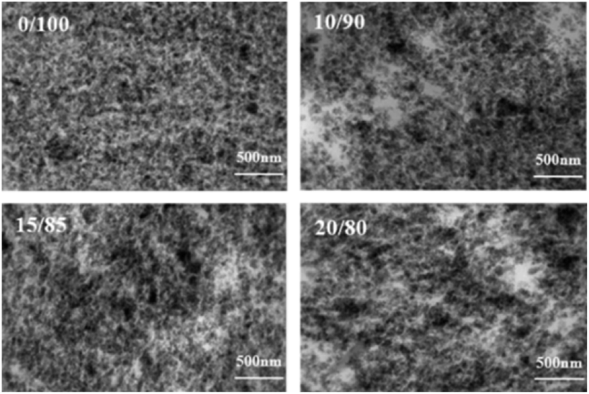 | ||
| Fig. 2 Silica dispersion morphology of VMQ/BR composites via TEM. | ||
Phase morphology
First, for exploring the reason of inhomogeneous silica dispersion in VMQ/BR composites, the two-phase morphology of VMQ–silica master-batch/BR blends has been observed via AFM and TEM15 in Fig. 3. As AFM Log DMT modulus photographs on the left, the darker areas of lower modulus refer to VMQ domains, and the brightest outer-layer surroundings refer to pre-mixed silica in VMQ master-batch, which demonstrate that silica particles have migrated to the interface between BR and VMQ phases after blending. Similar phenomenon could be observed in TEM images on the right, for most of the silica (dark particles) from VMQ master-batch present at the interface.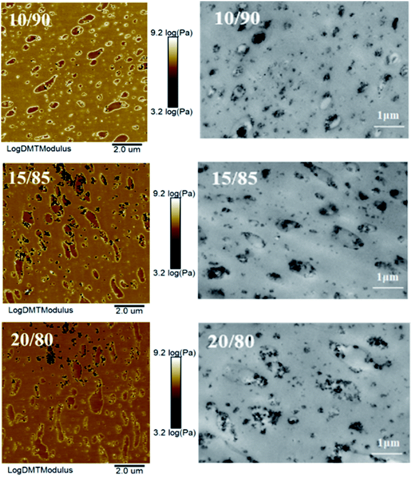 | ||
| Fig. 3 Two-phase morphology of VMQ–silica master-batch/BR blends via AFM (left) and TEM (right). | ||
Next, in Fig. 4, modulus scanning (along the red dotted line) performed on the surrounding of a single VMQ domain in 10/90 VMQ/BR blend has been done. As crossing BR matrix → interface silica particles → VMQ phase → interface silica particles → BR matrix, five distinct modulus regions (low → high → low → high → low) are clearly observed from the Log DMT modulus-length curve, which prove the existence of silica at interface again. The root of this phenomenon would be discussed in the following part.
 | ||
| Fig. 4 The Log DMT modulus scanning (along the red dotted line) on the surrounding of a single VMQ domain in 10/90 VMQ/BR blend. | ||
Last, VMQ phases exhibit both circular and elliptical shaped island structure in 10/90 blend, and as for most part, they present as elliptical and more irregular shaped domains in 15/85 and 20/80 blends, which is attributed to the worse interfacial compatibility with more VMQ addition. Besides, basing on the statistical results, the average domain size of VMQ phases is around 0.6 μm.
Surface characteristics
To deeply understand the origin of silica distribution at interface, surface energies of VMQ and BR have been determined19 as shown in Table 3, and surface energy of silica has referred to result of Heinrich et al.,20 for the same brand VN3 used. The interfacial interaction between filler and rubber could be evaluated by interfacial adhesive energy Wrf. The higher Wrf of BR–silica in Table 4 indicates stronger interfacial interaction between BR phases and silica than that of VMQ. This could be reasonable explain why silica migrate from VMQ domains internal to the interface after blending.| Surface energy (mJ m−2) | |||
|---|---|---|---|
| Dispersive part γd | Polar part γp | Total γ | |
| BR | 34.6 | 0.8 | 35.4 |
| VMQ | 23.0 | 0 | 23.0 |
| Silica | 23.7 | 6.0 | 29.7 |
| Wrf (mJ m−2) | γ12 (mJ m−2) | ωBR–VMQ | |
|---|---|---|---|
| BR–silica | 61.7 | 0.24 | — |
| VMQ–silica | 46.7 | 0.44 | — |
| BR–VMQ | — | 1.33 | 0.15 |
In addition, according to eqn (4) and (5), interfacial energies γ12 and wetting coefficient ωBR–VMQ have also been determined as listed in Table 4. As ωBR–VMQ = 0.15, ranging from −1 to 1, silica particles tend to distribute at the interface. This is consistent with the results above. Therefore, the interfacial selective location of silica is the main reason for the uneven filler distribution in VMQ/BR matrix.
Thermal oxidative aging properties
First, the tensile strength (TS) and elongation at break (EB) of VMQ/BR composites are presented in Fig. 5(a) and (b), respectively. With increasing VMQ content, TS gradually decreases, which is ascribed to the inherent weaker physical strength of VMQ, caused by its flexible –Si–O–Si– backbone of low cohesive energy density.21 Besides, as mentioned above, after introduction of VMQ, the poor interfacial compatibility (Fig. 3) and less homogeneous dispersion of silica (Fig. 2) would also deteriorate the mechanical strength. As for EB, there is no obvious change with the variation of VMQ fraction. | ||
| Fig. 5 Tensile strength (TS) and elongation at break (EB) of VMQ/BR composites. | ||
Next, the composites were exposed to 100 °C thermal oxidative aging for different time (12, 24, 36 h). Retention of TS (RTS) and EB (REB) after aging were calculated according to eqn (1) and (2), and the results are presented in Fig. 6(a) and (b), respectively. In the early stage of aging, under the action of heat and oxygen, the subsequent crosslinking of rubber chains has occurred, which stiffened the material, and resulted in the increase of TS instead of decrease, but at the same time, it usually led to the decrease of EB.22 Therefore, RTS and REB should be collaborative considered to judge the anti-aging behaviour.
 | ||
| Fig. 6 (a) The retention of TS (RTS) and (b) retention of EB (REB) of VMQ/BR composites after thermal oxidative aging for different hours (12, 24, 36 h). | ||
For RTS, within the investigated aging time, comparing with BR (0/100), it exhibits an increase in the three VMQ/BR blends, and all exceed 100%, proving the continued crosslinking during aging process. It is worth noting that RTS of 10/90 blend is much higher than that of 15/85 and 20/80 under 12 h aging, which is contributed by its better dispersed anti-aging VMQ domains in BR matrix (Fig. 3). With aging proceeds to 24 and 36 h, its superiority is no longer obvious, even surpassed by 15/85 and 20/80. Therefore, it is demonstrated that more VMQ should be added (e.g. 20 phr) when expose to a long-term aging. With regard to BR, RTS has increased evidently to a comparable level as VMQ/BR from 12 to 24 and 36 h, this could be explained by its less developed crosslinking network before aging (as lowest MH − ML shown in Table 2), for the post-crosslinking is more likely to happen, thus raise TS.
As for REB, similar with the trend of RTS, under aging time of 12 h, the three VMQ/BR composites present apparent higher values than BR; with prolonged 24 and 36 h, the preponderance of VMQ/BR has been weakened, as similar values could be seen between BR and 10/90 or 15/85. The stable highest REB level of 20/80 in the entire aging duration demonstrates the improved effect of VMQ on thermal oxidative aging resistance of BR composites again.
Last, in order to eliminate the effect of antioxidant during aging, VMQ/BR composites without antioxidant have also been prepared. As the retention of physical properties shown in Fig. 7(a) and (b), with increasing VMQ content up to 20 phr, RTS and REB both perform significant improvement comparing with 10/90 and 15/85 blends. As a result, even under the circumstances of non-antioxidant, VMQ could also greatly enhance the thermal oxidative aging resistance of BR composites.
 | ||
| Fig. 7 (a) RTS and (b) REB of VMQ/BR composites without antioxidants after thermal oxidative aging for different hours (24, 36 h). | ||
Ozone aging properties
For static ozone aging resistance testing, the cracks on sample surface were observed every 2 h. As shown in Fig. 8(a), emerging time of first cracking for the four composites become longer with increasing VMQ content, as 2, 4, 6 and 8 h for 0/100, 10/90, 15/85, 20/80 composites, respectively. For pure BR, emergence of first cracking was the earliest, and initial crack is pretty short and concentrated, like pinholes. | ||
| Fig. 8 Surface cracking morphology induced by ozone of VMQ/BR composites: (a) emergence of first cracking, (b) after ozone aging for 8 h. | ||
From photographs of surface morphology after ozone aging for 8 h shown in Fig. 8(b), very intensive cracks could be observed on surface of BR and the longest crack is about 2 mm. By contrast, the number of cracks on 10/90 and 15/85 composites surface has decreased significantly. As for 20/80, there only exists few cracks on the edge. Therefore, 20 phr VMQ could evidently improve ozone cracking resistance under static condition.
Based on the results above, mechanism of better ozone aging resistance for VMQ/BR is discussed by the scheme shown in Fig. 9. On the one hand, micro-cracks firstly generate in BR matrix under attack of ozone, and proceed to extend until encounter VMQ domains. Due to its excellent aging resistance resulting from the highly saturated –Si–O–Si– structure, cracks are harder to continue propagating through VMQ phases; on the other hand, the preferential location of silica at interface may also provide hinderance for subsequent crack propagation in VMQ phases. Therefore, the distributed VMQ–silica master-batch domains in BR matrix play essential role in reducing crack growth rate and preventing merge of microcracks to form macroscopic cracks.
 | ||
| Fig. 9 Mechanism sketch of the improved ozone aging resistance in VMQ/BR composites. | ||
Conclusions
In order to improve thermal oxidative and ozone aging resistance of BR, VMQ/BR blends are investigated in this study, and its microstructure has been intensively discussed. With increasing VMQ content, less homogeneous distribution of filler could be found, which is attributed to the migration of silica particles from VMQ master-batch to the interface, resulting from higher interaction between silica and BR phases.Further, it is found that after thermal oxidative aging, the physical properties retention rate of VMQ/BR are higher than that of BR; even under the condition of no protection from antioxidant, existence of 20 phr VMQ could also maintain excellent thermal oxidative anti-aging properties. The prolonged emerging time of first cracking, less amount and smaller size of cracks prove the improved ozone aging resistance of VMQ/BR. The highly saturated –Si–O–Si– backbone of VMQ plays the dominant role in enhancing thermal oxidative aging resistance of VMQ/BR, and dispersed VMQ domains in BR matrix and selective distribution of silica at interface contribute to the improved ozone cracking resistance. Especially, 20/80 VMQ/BR exhibits the best anti-ozone aging property and excellent thermal oxidative aging resistance even after 36 h.
Conflicts of interest
There are no conflicts to declare.Acknowledgements
The authors are grateful for the financial supports from the National Key Research and Development Program of China (No. 2017YFB0307002).References
- R. Casalini, K. L. Ngai, C. G. Robertson and C. M. Roland, J. Polym. Sci., Part B: Polym. Phys., 2000, 38, 1841–1847 CrossRef CAS.
- G. R. Hamed and H. J. Kim, Rubber Chem. Technol., 1999, 72, 895–909 CrossRef CAS.
- A. S. Hashim, B. Azahari, Y. Ikeda and S. Kohjiya, Rubber Chem. Technol., 1998, 71, 289–299 CrossRef CAS.
- H. Zhang, R. N. Datta, A. G. Talma and J. W. M. Noordermeer, Rubber Chem. Technol., 2009, 82, 379–399 CrossRef CAS.
- W. H. Waddell, Rubber Chem. Technol., 1998, 71, 590–618 CrossRef CAS.
- F. Ignatz-Hoover, B. H. To, R. N. Datta, A. J. De Hoog, N. M. Huntink and A. G. Talma, Rubber Chem. Technol., 2003, 76, 747–768 CrossRef CAS.
- K. Sahakaro, N. Naskar, R. N. Datta and J. W. Noordermeer, Rubber Chem. Technol., 2007, 80, 115–138 CrossRef CAS.
- A. H. Speranzini and S. J. Drost, Rubber Chem. Technol., 1970, 43, 482–500 CrossRef CAS.
- K. Sahakaro, R. N. Datta, J. Baaij and J. W. Noordermeer, J. Appl. Polym. Sci., 2007, 103, 2555–2563 CrossRef CAS.
- F. M. Lewis, Rubber Chem. Technol., 1962, 35, 1222–1275 CrossRef CAS.
- K. E. Polmanteer, Rubber Chem. Technol., 1981, 54, 1051–1080 CrossRef CAS.
- S. C. Shit and P. A Shah, Natl. Acad. Sci. Lett., 2013, 36, 355–365 CrossRef CAS.
- Z. Sun, Q. Huang, Y. Z. Wang, L. Q. Zhang and Y. P. Wu, Ind. Eng. Chem. Res., 2017, 56, 1471–1477 CrossRef CAS.
- Z. Sun, Q. Huang, L. Q. Zhang, Y. Z. Wang and Y. P. Wu, RSC Adv., 2017, 7, 38915–38922 RSC.
- Q. Y. Han, L. Q. Zhang and Y. P. Wu, RSC Adv., 2019, 9, 29813–29820 RSC.
- D. K. Owens and R. C. Wendt, J. Appl. Polym. Sci., 1969, 13, 1741–1747 CrossRef CAS.
- F. M. Fowkes, J. Phys. Chem., 1963, 67, 2538–2541 CrossRef CAS.
- R. Ibarra-Gómez, A. Márquez, L. F. Ramos-de Valle and O. S. Rodríguez-Fernández, Rubber Chem. Technol., 2003, 76, 969–978 CrossRef.
- C. Wan, W. Dong, Y. Zhang and Y. Zhang, J. Appl. Polym. Sci., 2008, 107, 650–657 CrossRef CAS.
- K. W. Stöckelhuber, A. S. Svistkov, A. G. Pelevin and G. Heinrich, Macromolecules, 2011, 44, 4366–4381 CrossRef.
- I. Yilgör and J. E. Mcgrath, Adv. Polym. Sci., 1988, 86, 1 CrossRef.
- K. Gong, G. Li and Q. Hu, J. Polym. Sci., Part A: Polym. Chem., 1991, 29, 1225–1230 CrossRef CAS.
Footnote |
| † L. Leng and Q. Y. Han contributed equally to this work. |
| This journal is © The Royal Society of Chemistry 2020 |