 Open Access Article
The effect of solid content on the rheological properties and microstructures of a Li-ion battery cathode slurry
Lixia Ouyangabc,
Zhaohui Wub,
Jun Wangd,
Xiaopeng Qib,
Qiang Liabc,
Jiantao Wang *abc and
Shigang Luabc
aNational Power Battery Innovation Center, GRINM Group Co., Ltd., Beijing 100088, China. E-mail: jiantaowang2002@126.com
bChina Automotive Battery Research Institute Co., Ltd., Beijing 100088, China
cGeneral Research Institute for Nonferrous Metals, Beijing 100088, China
dScience Institute of Big Data, Zhengzhou University of Aeronautics, Zhengzhou 450046, China
First published on 20th May 2020
Abstract
The development of new materials and the understanding of the microstructure formation of electrodes have become increasingly important for improving Li-ion battery performance. In this study, we investigate the effect of solid content on the rheological properties of and the microstructures in the cathode slurry prepared from Ni-rich materials. With long-chain structures, PVDF molecules can change their configurations when they come into contact with the solid particles in slurries, and their bridging function can change with the solid content in the slurry. Below the optimum content, particle sedimentation easily takes place. Above the optimum content, excessive yield stress is created in the slurry, and this stress is not conducive to homogeneous distribution of the components. The rheological properties of the slurries vary greatly under different solid contents. We investigated the uniformity and stability of the slurry prepared from Ni-rich materials and found that the most suitable solid content of the slurry lies in the range from 63.9% to 66.3%. Our work might assist in the production of high-performance Li-ion batteries that are made using an electrode slurry.
1. Introduction
Li-ion batteries have been widely used in consumer electronics and electric vehicles due to their advantages of high energy density, long cycle life, and high operating voltage, among others.1–3 Currently, most electrodes of Li-ion batteries are produced by coating an electrode slurry layer on a metal current collector followed by drying. The electrode, which hosts the main electrochemical reactions in the Li-ion battery and is responsible for most of the failures in Li-ion batteries,4 is directly affected by the slurry and the later coating process. Hence, it is the slurry that primarily determines the final electrochemical properties, performances, and failures of the electrode. Additionally, the performance of the slurry also affects its processability,5 the productivity of manufacturing equipment and the shape of the electrode.Generally, the slurry is a typical non-equilibrium particle suspension system that contains solvents, micron- or submicron-sized active materials, and conductive agents and binders of submicron size or even sizes less than 100 nm.6 These components differ in size, density and shape such that they prefer to separate during or after slurry fabrication.7–9 The overall performance of the electrode coatings is largely determined by the uniformity and stability of the slurries, which is crucial for the quality of the Li-ion battery. For a colloidal battery slurry, the main problems are sedimentation of large particles and agglomeration of small particles. During the Li-ion battery fabrication process in the factory, because of the actual fabrication arrangement or other processes that require venting (and other factors), application of the slurry might not be possible immediately after stirring, and therefore, the slurry must remain stable during the storage period before coating. Poor slurry stability can cause sedimentation of the slurry components and weakening of the overall performance and production efficiency of the coated electrode, which are detrimental to the quality of the battery.
Three common strategies are used to improve the anti-settling stability of the slurry. In the first strategy, repulsive electrostatic effects or spatial barriers are applied to the particles in the slurry to prevent discrete particles from forming larger agglomerates.10,11 However, this approach can only suppress sedimentation of rather small particles. The second strategy reduces the mobility of particles in the slurry, which can be easily realized by increasing the viscosity of the slurry, e.g., by adding a thickener.12 A higher viscosity decreases the particle kinetic energies and prevents particles from repelling the energy barriers, thus slowing the particle sedimentation process. However, the effectiveness of this approach is quite limited for large particles. The third and more effective strategy is based on formation of a weakly coagulated state, i.e., network connections, among the solid particles in the slurry.13 In this case, a cohesive and non-connected network consists of individual particles and is sufficiently large to spread to the entire slurry volume.14–17 A suitable network connection can supply sufficient attraction to stabilize itself against gravitational effects and has sufficient load capacity to prevent it from merging due to its own weight, rendering it flowable even at low shear rates and aiding in reforming when flow stops. Therefore, interactions among the particles or between the particles and the polymers, such as electrostatic repulsion, steric hindrance or flocculation, could form different microstructures in slurries, thus achieving uniformity of each component and ensuring the overall stability of the slurry. Moreover, the microstructures of the electrode coating are determined by the microstructure formed by the components in the slurry.
Normally, the stability of slurries is greatly influenced by the solid content. Obviously, increasing the solid content could reduce the drying time in battery production and thus improve production efficiency. Ligneel et al.18 investigated the effect of solvent concentration on the processing and performance of composite electrodes and found that for excessively low or high concentrations, the electrode dispersion respectively exhibited yield stress or a concentration gradient caused by sedimentation of particles, and the electrochemical performance was reduced due to poor electronic wiring of the active material. However, the microstructures and their formation mechanisms in the slurry at different solvent concentrations corresponding to various solid concentrations have not yet been studied. In general, different solvent concentrations lead to different rheological properties due to different internal microstructures, resulting in different battery performances.
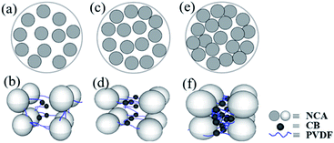
In this study, we investigated the effect of solid content on the microstructure of the cathode slurry system made with a Ni-rich cathode material, LiNi0.8Co0.15Al0.05O2, one of the most promising cathode material candidates19–21 due to its high theoretical capacity and discharge voltage. Rheological tests of the slurry and SEM images of the dried slurry coatings revealed the change in the microstructure of the slurry at different solid contents. The correlations between the microstructure of the slurry and the dispersion uniformity and stability of the cathode slurry at different solid contents were analyzed. In addition, we predicted three cases of the dispersibility and microstructure of the slurry in different solid contents, as shown in Fig. 1: (1) at low solid content, the dispersibility of the cathode particles in the slurry is good, the binder molecules exist in an extended state, and the interaction forces between the particles and between the particles and the binder are notably weak, as shown in Fig. 1(a) and (b). (2) At intermediate solid content, the cathode particles in the slurry are most uniformly dispersed, and the interaction forces among the particles and between the particles and the binder are moderate, as shown in Fig. 1(c) and (d). (3) With further increase in the solid content to high values, the cathode particles are closely connected, the binder molecules exist in a collapsed state, and the force among the particles and between the particles and the binder is notably strong, and the dispersibility of the cathode particles in the slurry is reduced, as shown in Fig. 1(e) and (f).
2. Experiments
2.1. Sample preparation
Ni-rich materials (LiNi0.8Co0.15Al0.05O2, denoted NCA, Battery, China) with a mean particle size of 12.62 μm and a BET specific surface of 1.62 m2 g−1 were used as the active material. Carbon black (CB) was used as a conductive agent, and the binder was PVDF. The three materials were used at a mass percentage ratio of 94![[thin space (1/6-em)]](https://www.rsc.org/images/entities/char_2009.gif) :
:![[thin space (1/6-em)]](https://www.rsc.org/images/entities/char_2009.gif) 3:3. NMP was used as the solvent.
3:3. NMP was used as the solvent.
First, the binder was dissolved in NMP at ambient temperature. The active material and conductive agent were mixed in advance. Mixtures consisting of powders and binder stock solution were adjusted with additional NMP to different solid contents using a magnetic stirrer at 2000 rpm. The viscosity of each freshly prepared slurry was tested with a viscometer.
2.2. Characterization of the rheological properties of the cathode slurry
Rheological tests were conducted using steady-state flow, frequency sweep and thixotropy tests. A rheometer (Kinexus Pro, The United Kingdom) with plate–plate geometry (PU40, gap = 1 mm) at 25 °C was used in the tests. Measurements were performed immediately after the mixing process was completed. Prior to all measurement runs, the inserted samples were exposed to a five-minute equilibrium period to ensure the correct temperature of the samples and an acceptable level of the residual normal force.The fineness of the slurry was tested by a scraper fineness meter (MC, China). In the test, the slurry was dropped into the deepest portion of the groove, and the scraper was pulled over the entire length of the groove at a suitable speed. After the sample was scraped, the uniformly exposed depth of the particles in the groove was immediately observed. The thickness obtained from 3 measurements represented the fineness of the slurry.
An appropriate amount of the slurry was collected and placed in a transparent glass bottle to observe the sedimentation state of the slurry.
2.3. SEM images of the dried slurry coatings and electrode
Aluminum foil containing approximately 1 g of fresh slurry was placed in an electric blast oven (DHG-9075) for rapid drying. The morphology of the dried slurry coatings and the electrode surface was observed by the FE-SEM (HITACHI S-4800).3. Results and discussion
Fig. 2(a) shows the fineness and viscosity of the cathode slurries containing different solid contents ranging from 57.2% to 69.5%. The fineness of the slurries with solid contents ranging from 57.2% to 67.6% remained low. For solid content ranging from 67.6% to 69.5%, the fineness of the slurries greatly increased. The main reason for this result is that slurry with different solid content is continuously mixed with the same shear force during the mixing process. If the solid content is low, the internal particles undergo a process of dispersing the aggregated clusters and recombining the suspended clusters, which can be well dispersed and form smaller aggregates.22 When the solid content is high, the dispersion speed of the particles in the slurry under the same shear force is slower than its re-aggregation speed, and thus it cannot be well dispersed, and eventually, a large-size hard aggregate cluster is formed. The change in viscosity with solid content is generally consistent with the change in fineness with solid content and also increases with the increase in solid content. The viscosity of the slurries increases as the solid content increases from 67.5% to 69.5%. From Fig. 2(b) we can intuitively observe the effect of the solid contents on the flow properties of the slurry. Slurries with solid content between 57.2% and 63.2% possess good fluidity, whereas fluidity fades as the solid content increases to 67.6%, and their viscosities also decline. As the solid content further increases to 68.4% and 69.5%, the slurries show poor flow properties and appear mushy. The fluidity of the slurry generally decreases with increasing solid content, and especially under the condition of high solid content, the tendency of the fluidity to decrease is increasingly obvious.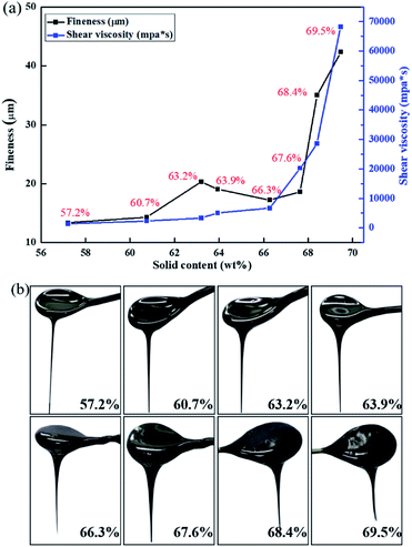 | ||
| Fig. 2 (a) Fineness and viscosity of the cathode slurries as a function of solid content. (b) Flow diagram of slurries with different solid contents. | ||
Fig. 3(a) shows the shear viscosity versus shear rate for slurries with different solid contents. The viscosity at low shear rate represents the stability of the slurry, which is a measure of the solid sedimentation behavior, whereas the viscosity at high shear rate is a measure of the slurry processability.23 It can be observed that the viscosity curves of different solid contents decrease with the increase in shear rate, i.e., shear thinning behavior exists, which means that all of the slurries are non-Newtonian fluids and agglomerates exist.
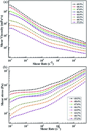 | ||
| Fig. 3 (a) Shear viscosity vs. shear rate and (b) shear stress vs. shear rate under different solid contents. | ||
The agglomerates can be broken by applying a lower shear stress adjustable by the shear rates. Over the entire range of shear rates, the viscosity of the slurry at different solid contents increased with the increase in solid content. The viscosity of the slurry with solid contents of 57.2% and 60.7% decreases at a low shear rate, indicating that the anti-settling characteristics of the solid content are not significant, i.e., the slurry has poor stability. The viscosity of the slurry with solid contents ranging from 63.9% to 69.5% is notably high at low shear rates, whereas at the same shear rate, the viscosity of the slurry doubles as the solid content increases. This result indicates that the anti-settling characteristics of the solid components in the slurry become increasingly stable, meaning that the stability of the slurry is enhanced as the solid content increases. But the trends are not exactly the same. When the solid content is increased from 63.2% to 63.9%, the viscosity of the slurry increases dramatically at a low shear rate. When the solid content increases from 63.9% to 66.3%, the viscosity difference of the slurry at a low shear rate is notably small, and the two curves generally coincide.
Low viscosity at high shear rates is also an advantageous feature because coatings with lower viscosity pastes are more uniform. It can be assumed that coating of the slurry with a solid content from 57.2% to 63.2% is relatively more uniform, and the uniformity of the coating obtained by the slurry with a solid content from 68.4% to 69.5% is relatively lower.
The shear stress vs. shear rate is presented in Fig. 3(b). In accordance with Fig. 3(a), which shows that viscosity increases with increasing solid content at a fixed shear rate, the shear stress also increases with increasing solid content. When the solid content ranges from 57.2% to 63.2%, the shear stress of the slurry increases with the shear rate, and a platform trend appears in the curve as the solid content ranges from 60.7% to 63.2%. When the solid content increases to 63.9%, the curve forms a platform, and this phenomenon corresponds to the large increase in the viscosity at low shear rate as the solid content ranging from 63.2% to 63.9% in Fig. 3(a). The fact that the shear stress does not change with the shear rate indicates the presence of yield in the slurry. The existence of the yield phenomenon indicates that a network structure exists across the volume in the slurry, and a structural change occurs in the slurry. The transition from a network structure to a liquid-like system is caused by broken connections between particles.13 Instead of occurring instantly, this process of destruction is gradual, corresponding to a transition area after the platform rather than a point of sudden transition. If we define the point at which the transition begins as the yield point, the stress at this point is the yield stress, and this yield stress is the minimum stress that leads the slurry to flow.24 It is obvious that the yield stresses present in the slurry with solid contents of 63.9% and 66.3% are relatively mild, and the yield stress increases with increasing solid content.
The storage (G′)/loss (G′′) modulus vs. frequency for different slurries are shown in Fig. 4. For slurries with a solid content of 57.2% and 60.7%, G′′ > G′ during the entire test range, and both moduli are frequency dependent. This result indicates that the slurry with solid content of 57.2% and 60.7% exists in a low-viscosity sol state. A difference is also noted between the viscoelasticity of these two slurries in the sol state. The values of G′′ and G′ of the 60.7% solid content slurry and the difference between them are much higher than those in a slurry with solid content of 57.2%, and the dependence of G′ to frequency of the 60.7% solid content slurry is relatively lower. This result is primarily attributed to the formation of a bridging flocculation structure between the particles and the binder in the 60.7% solid content slurry, which is reflected in the subsequent SEM image of the dried slurry coatings.
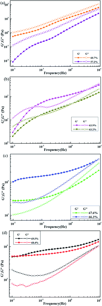 | ||
| Fig. 4 Storage modulus (G′) and loss modulus (G′′) vs. frequency for slurries with different solid content: (a) 57.2–60.7%, (b) 63.2–63.9%, (c) 66.3–67.6% and (d) 68.4–69.5%. | ||
As the solid content increases, the modulus value of the slurry gradually increases, and G′ is much greater than G′′. The frequency-dependent trend is also lower, and the slurries are gradually changed from a sol state to a gel state. When the solid content is increased to 66.3%, G′ > G′′, and G′ has low frequency dependence. This result shows that the 66.3% solid slurry is already in a gel state. However, the G′ and G′′ of the 66.3% solid content slurry increase by several times compared with the 67.6% solid content slurry, indicating that the particle-to-particle and particle–solvent interactions in the slurry are stronger.25 The solid characteristics of the 66.3% solids slurry are significantly stronger than those of the 67.6% solids slurry, which is opposite to the former tendency. Possible reasons are that the active material, conductive agent and binder in the 66.3% solid content slurry are more uniformly distributed, and the weakly condensed network structure formed by the mutual interaction connects the entire system, making the slurry show more pronounced solid-state characteristics. When the solid content is further increased, the van der Waals force of the mutual attraction among the active material particles is stronger, the agglomeration of the active material is stronger, and the common interaction between the active material, the conductive agent, and the binder is relatively reduced. However, the agglomeration effect of the active materials in forming a cross-network structure is lower than the common interaction of the active materials, conductive agents, and binders. As a result, as the solid content increases, the solid characteristics of the slurry decrease.
When the solid content is increased to 68.4% and 69.5%, the G′ of the slurry is greater than G′′ in the entire test frequency range, and the elastic modulus G′ shows notably low frequency dependence. This result indicates that both of these slurries exist in a solid state, and the solid-state characteristics of the 69.5% slurry are relatively more obvious.
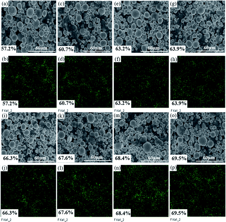
As the solid content increases, the rheological state of the slurry and its microstructure can be confirmed by the SEM images of the dried slurry coatings shown in Fig. 5.
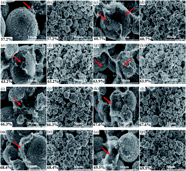 | ||
| Fig. 5 SEM images of dried slurry with different solid content: (a) & (b) 57.2%, (c) & (d) 60.7%, (e) & (f) 63.2%, (g) & (h) 63.9%, (i) & (j) 66.3%, (k) & (l) 67.6%, (m) & (n) 68.4%, (o) & (p) 69.5%. | ||
Fig. 5(a) and (b) show that the PVDF and conductive agent in the 57.2% solid slurry did not form a connection network at the surface of the cathode or among the particles. This observation is consistent with the apparent liquid characteristics of the 57.2% slurry and the curve of the shear stress-shear rate. Fig. 5(c)–(h) show that a film is formed by the conductive agent and the binder, and it uniformly covers the surface of the active material particles and is connected among the cathode particles. The structure is as predicted by Fig. 1(c) and (d).
CB can be electrostatically stable in NMP without the need for an additional dispersant because these particles are charged by a counterion from a dissociated surface group.13,26 PVDF molecules change their configuration when they contact the solid interface. One end of the polymer chain can be adsorbed on the surface of the particle to form a sequential structure while the other components extend into the solvent as a ring or tail.13,27 CB nanoparticles supply fewer adsorption sites for individual binder PVDF molecules, and polymer chains protrude from the surface of the CB nanoparticles. The protruding polymer chains can interact with other particles or another adsorbed binder polymer chains. Furthermore, when the chain ends of a polymer chain are adsorbed on different particles, bridging flocculation is formed.13 The reason why the network structure was not formed in the 57.2% solid slurry might be related to the size of the cathode particles and the distance between the particles. For details, please refer to Table 1. The PVDF molecules are much smaller than the cathode particles, and the distance between the cathode particles is larger.13 The binder molecules adsorbed on the surface of one particle cannot be connected to another cathode particle such that bridging flocculation cannot be formed, and its structure is as predicted by Fig. 1(a) and (b). The binder molecules cannot form an attractive network, and thus the anti-settling stability is notably low. Fig. 5(c) shows that the bridge flocculation structure between CB-PVDF and the cathode particles-PVDF forms a film uniformly wrapped on the surface of the active particles. This effect could avoid direct contact between particles, which is beneficial to uniform dispersion of the components in the slurry. From Fig. 5(d), (f) and (h), it can be observed that in addition to the surface of the cathode particles, the bridging flocculation that also exists between the cathode particles could increase as the solid content increases. The weakly condensed network structure is gradually strengthened, which is helpful to enhancing the anti-settling stability of the slurry. In addition, although slurries with solid contents from 60.7% to 63.2% contain a weak coagulation network formed by bridging flocculation, it cannot enable the connected particles to transfer forces and support shear stress.18 Therefore, the platform feature tends to appear in its shear stress-shear rate, but the platform is not truly formed.
| Solid content | ρ (g cm−3) | VAM (cm3) | n | m (μm) |
|---|---|---|---|---|
| a ρ is the density of the slurry. Setting the size of the cube of the slurry to 1 cm3, VAM is the volume of densely packed active material particles contained in a 1 cm3 cube of slurry, n is the number of particles of the active material on the side length of the densely packed cube, and m is the distance between the active material particles in the slurry cube. It is assumed that all active materials are uniformly distributed particles of equal diameter in the slurry. | ||||
| 57.2% | 1.7695 | 0.3731077 | 571 | 4.901715 |
| 63.9% | 1.9909 | 0.4667171 | 614 | 3.666649 |
| 69.5% | 2.2578 | 0.5652071 | 655 | 2.651223 |
Although bridging flocculation can be observed in the 66.3% solid slurry in Fig. 5(i), the bridging is not uniformly coated on the surface of the cathode particles but primarily exists among the cathode particles. This phenomenon is observed in the high-magnification SEM images of dried slurry coatings with a solid content greater than 66.3% because the increase in the solid content is accompanied by an increase in the active material. The van der Waals force, which is mutually attractive between the active materials, is enhanced due to the increase in the active material content, but the shortening of the distance between particles also enhances the van der Waals force. The van der Waals force that causes agglomeration of the cathode particles is greater than the bridging flocculation, which is also strengthened by the increase in the solid content, thus reducing the uniformity of adsorption of the flocculation on the surface of the cathode particles.
From Fig. 5(j) and (l) of the low-magnification SEM images of the 66.3% and 67.6% solid content slurry, it is found that the distribution of bridging flocculation between the cathode particles in the 66.3% slurry is more uniform, and this might be the reason why the viscosity of 66.3% solids slurry is lower, but its solid-state characteristics are more obvious. The solidity characteristic of the 66.3% solid content slurry is more obvious than that in the 66.7% solid content slurry. This observation can also be observed from the relationship diagram of modulus vs. frequency. The solid-state characteristics of the slurry are mainly caused by the network structure formed by the bridging flocculation between the particles and the binder, and no direct contact occurs between the cathode particles.
From the SEM images of the 68.4% and 69.5% solid content slurry in Fig. 5, it can be observed that the bridging flocculation exists only in a certain area on the surface of the cathode particles, its distribution uniformity is greatly reduced, and its structure is as predicted by Fig. 1(e) and (f). The solid-state properties of the 68.4% and 69.5% solid content slurry are mostly caused by the connection of the cathode particle units to form a volume-filled particle network structure, and the particles contact each other, rather than by bridging flocculation adsorbed on the surface of the cathode particles, forming a network structure. PVDF exists in a curled state, and PVDF has more interactions with CB particles and the remaining PVDF molecular chains. The existence of such a granular network structure could greatly improve the anti-settling stability of the slurry, but it could reduce the uniform dispersion of the slurry components.
In addition, the dispersion uniformity of the slurry components can also be reflected in the EDS diagram of the electrode pads. Fig. 6 shows a fluorine element EDS mapping of an electrode pad under different solid contents. With the increase in the solid content, the degree of agglomeration of the small cathode particles and the conductive agent on the surface of the electrode is more obvious, and the uniformity of the distribution of elemental fluorine is also reduced. Fig. 6(b) shows an electrode prepared with a 57.2% solid content slurry. The distribution of fluoride is worse than that of the electrode fabricated using slurry with 63.2% and 63.9% solid content. Because of the liquid characteristics of the 57.2% slurry, the viscosity of the slurry is the lowest. During the drying process of the freshly coated electrodes, the excess PVDF dissolved in the solvent migrates upward as the solvent evaporates such that the distribution of the binder changes again. Another reason is that no weakly condensed network structure exists in the slurry. The F element in the 66.3% solid content electrode has a more uniform distribution than that in the 67.6% solid content electrode, which is also consistent with the above analysis results of the structure in Fig. 5(j) and (l).
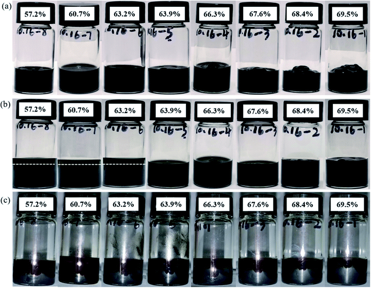
The anti-settling stability of the slurry at different solid contents can also be evaluated via the layering status of the slurry after standing. Fig. 7 shows the slurry states for as-prepared materials and after a period of storage. Fig. 7(b) shows that the slurry with the solid content of 50.7–63.2% has exhibited delamination after standing for 45 days, while the other solid content slurry has not exhibited delamination, indicating that the anti-settling stability of the slurry increases with the rise of solid content. And the slurry with solid content of 63.9–69.5% still has good stability after 45 days. Fig. 6(c) shows that the slurry at different solid content have been delaminated after 6 months of standing, indicating that the stability of the slurry at different solid contents could not reach such a long time. Obviously, the upper suspension of the slurry is more transparent at low solid content. Although the slurry shows delamination at high solid content, the transparency of the upper suspension is lower. Regardless of the state of the stationary freshly prepared slurry, the medium particles of the slurry must be affected by gravity. Gravity (Fg) can be calculated according to the following equation,
| Fg = 4(ρρ − ρm)πr3g/3 | (1) |
The thixotropic recovery of the slurry during the three stages of low-shear/high-shear/low-shear testing reflects the strength of the binding force between the dispersed particles in the slurry and the dispersion stability.29
As shown in Fig. 8, the viscosity curve of the slurry under different solid contents shows that the viscosity of each slurry decreases significantly under the action of a constant high shear rate. When the shear rate decreases again, the viscosity of the slurry gradually increases because during high shear flow, the flocculent structure formed by the intermolecular forces in the slurry is gradually destroyed under the effects of shear stress, such as disaggregation between particles, stretching and disentanglement of polymers, etc.30 When the shear rate is reduced, the damaged flocculation structure in the slurry could recover, and the difference between the degree of recovery and the original is expressed as the viscosity difference between the first and third stages in the curve. It can be observed from Fig. 8(a) that the difference between the viscosity of the first and third stages of the 57.2% solid slurry is negative, i.e., the highest viscosity of the third stage is greater than the viscosity of the first stage. However, the difference between the viscosity of the first stage and the third stage of other solid content pastes is positive because the binding force between the dispersed substances in the 57.2% solid slurry is notably low, and it is not able to form a bridge flocculation structure that can span a certain volume. After the components are destroyed by high shear force, as the shear force decreases, new agglomerates are easily formed between the components, which increases the viscosity of the slurry. The other solid content in the slurry bridges the flocculating structure, even if the strength of the structure is different. In the bridge structure of the slurry with low solid content, each component is uniformly dispersed, and the structure can be restored to a certain level after the structure is destroyed. In the slurry with high solid content and a bridged flocculation structure, the gel structure is notably strong and can transmit force and withstand certain shear stress, and thus it can restore the original state to a certain degree. The thixotropic recoverability of each slurry can also be reflected by the magnitude of the structural recovery time of Fig. 8(b). The structure recovery time is defined as the time required for the viscosity of the third stage to return to the maximum value of this stage or 90% of the absolute value of the viscosity of the first stage. This measure is used to indicate the speed of the viscosity recovery, i.e., the thixotropy of the slurry. The longest structural recovery time of 600 s occurs in slurry with 57.2% solid content, which is much longer than the structural recovery time of other slurries. When the solid content is increased, the structure recovery time of the slurry is greatly shortened, and as the solid content is further increased, the structure recovery time of the slurry decreases. At high solid contents, the structure recovery time of the slurry does not vary substantially.
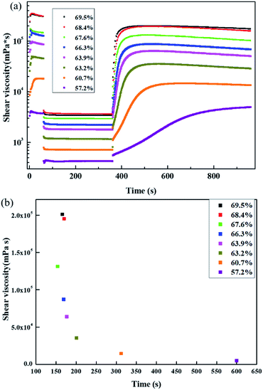 | ||
| Fig. 8 (a) Viscosity vs. time and (b) structure recovery time of slurry at different solid contents. | ||
The thixotropy of the slurry is highly important for coating and drying of the electrode pads. For example, the structure recovery of 69.5% and 68.4% solid content slurry is quite fast, the viscosity of the slurry increases quickly, and the viscosity value of the slurry is too high. The slurry is already dried before it is leveled, and thus the quality of the prepared pole pieces is poor. The structure recovery of the 57.2% slurry is notably slow, the final viscosity is small, and the slurry easily flows, reducing the stability of the prepared electrode coating.
4. Conclusions
This work investigates the effect of solid content in a cathode slurry prepared from a high nickel material on the microstructure of the slurry. The microstructure of the slurry was estimated using rheological measurements and was confirmed by SEM images of the dried slurry coatings. The influence of the solid content on the dispersion uniformity and the stability of the cathode slurry was discussed.PVDF molecules with long chain structure could be adsorbed on the surface of different particles, forming bridge flocculation. In the slurry with the lowest solid content of 57.2%, the binder cannot form bridge flocculation with the cathode particles because the size of the cathode particles and the distance between them are too large. Although the slurry exists in a sol state with low viscosity, the dispersion uniformity of the components is not the best.
For solid contents between 60.7% and 63.9%, bridging flocculation forms between the solid particles, and the binder evenly distributes the conductive agent and the binder on the surface of or between the cathode particles, forming a weak flocculation network structure, and thus the slurry changes from a sol state to a gel state. The existence of a weak flocculation network structure is beneficial to improvement of the dispersion uniformity and stability of the slurry. However, when the strength of the structure is weak, no yield stress exists in the slurry.
The further increased attraction between the solid particles exceeds the bridging effect between the particles and the binder when the solid contents are 66.3% to 69.5%, such that the binder and the conductive agent are more distributed between the cathode particles or a portion of the surface of the particles. This leads to great enhancement of the stability of the slurry but decreases the dispersion uniformity. Although the slurries in this range all exhibit gel characteristics, differences exist in the reasons for their formation. The gel structure in the slurry with solid content in the range of 66.3% and 67.6% is mainly caused by the network structure formed by bridging flocculation between particles and the binder, and no direct contact occurs among particles. However, the solid-state characteristics of 68.4% and 69.5% solid content slurries are primarily caused by the cathode particle units connected together to form a volume-filled particle network structure, and the particles can contact each other.
In this study, when the dispersion uniformity and stability of the slurry prepared from the high nickel cathode material were comprehensively considered, it was found that the most suitable solid content of the slurry ranged from 63.9% to 66.3%. Although the solid content is an important parameter in the production of lithium-ion battery slurry, little research exists on the microstructure of the slurry with respect to solid content. This article has important reference value for solid content design of lithium-ion battery slurry.
Conflicts of interest
The authors declare that they have no conflict of interest.Acknowledgements
This work was supported by Beijing Natural Science Foundation (grant numbers L182023), Huairou District Technology Program (grant numbers gy2019-2) and The National Key Research and Development Program (grant numbers 2016YFB0100206).References
- H. Wu, G. Yu and L. Pan, et al., Stable Li-ion battery anodes by in-situ polymerization of conducting hydrogel to conformally coat silicon nanoparticles, Nat. Commun., 2013, 4(1), 1–6 Search PubMed
.
- M. Armand and J.-M. Tarascon, Building better batteries, Nature, 2008, 451(7179), 652–657 CrossRef CAS PubMed
.
- J. M. Tarascon and M. Armand, Issues and challenges facing rechargeable lithium batteries, Nature, 2001, 414, 359–367 CrossRef CAS PubMed
.
- Q. Wang, S. Wang and J. Zhang, et al., Overview of the failure analysis of lithium ion batteries, Energy Storage Sci. Technol., 2017, 6(5), 1008–1025 Search PubMed
.
- B. Bitsch, J. Dittmann and M. Schmitt, et al., A novel slurry concept for the fabrication of lithium-ion battery electrodes with beneficial properties, J. Power Sources, 2014, 265, 81–90 CrossRef CAS
.
- S. Lim, S. Kim and K. H. Ahn, et al., The effect of binders on the rheological properties and the microstructure formation of lithium-ion battery anode slurries, J. Power Sources, 2015, 299, 221–230 CrossRef CAS
.
- I. S. Aranson and L. S. Tsimring, Patterns and collective behavior in granular media: theoretical concepts, Rev. Mod. Phys., 2006, 78(2), 641–692 CrossRef CAS
.
- N. H. Kwon, The effect of carbon morphology on the LiCoO2 cathode of lithium ion batteries, Solid State Sci., 2013, 21(1), 59–65 CrossRef CAS
.
- M. Zhu, J. Park and A. Sastry, et al., Numerical study of interaction and aggregation of non-spherical particles in forming Li-ion battery cathodes, J. Electrochem. Soc., 2014, 161(9), A1247–A1252 CrossRef CAS
.
- V. Subramanian, K. I. Gnanasekar and B. Rambabu, Nanocrystalline SnO2 and In-doped SnO2 as anode materials for lithium batteries, Solid State Ionics, 2004, 175(1), 181–184 CrossRef CAS
.
- S. Zürcher and T. Graule, Influence of dispersant structure on the rheological properties of highly-concentrated zirconia dispersions, J. Eur. Ceram. Soc., 2005, 25(6), 863–873 CrossRef
.
- C. Chae, H. J. Noh and J. K. Lee, et al., A high-energy Li-ion battery using a silicon-based anode and a nano-structured layered composite cathode, Adv. Funct. Mater., 2014, 24(20), 3036–3042 CrossRef CAS
.
- W. Bauer and D. Nötzel, Rheological properties and stability of NMP based cathode slurries for lithium ion batteries, Ceram. Int., 2014, 40(3), 4591–4598 CrossRef CAS
.
- J. Wang, Y. Chen and L. Qi, The development of silicon nanocomposite materials for Li-ion secondary batteries, Open Mater. Sci. J., 2011, 5(1), 228–235 CrossRef CAS
.
- J. Davies and J. Binner, Coagulation of electrosterically dispersed concentrated alumina suspensions for paste production, J. Eur. Ceram. Soc., 2000, 20(10), 1555–1567 CrossRef CAS
.
- X. Hou, S. Hu and R. Qiang, et al., The roles of intermediate phases of Li-Si alloy as anode materials for lithium-ion batteries, Rare Met. Mater. Eng., 2010, 39(12), 2079–2083 CrossRef CAS
.
- J. A. Lewis, Colloidal processing of ceramics, J. Am. Ceram. Soc., 2000, 83(10), 2341–2359 CrossRef CAS
.
- E. Ligneel, B. Lestriez and A. Hudhomme, et al., Effects of the solvent concentration (solid loading) on the processing and properties of the composite electrode, J. Electrochem. Soc., 2007, 154(3), A235–A241 CrossRef CAS
.
- W. Li, B. Song and A. Manthiram, High-voltage positive electrode materials for lithium-ion batteries, Chem. Soc. Rev., 2017, 46(10), 3006–3059 RSC
.
- F. Schipper, E. M. Erickson and C. Erk, et al., Recent advances and remaining challenges for lithium ion battery cathodes, J. Electrochem. Soc., 2016, 164(1), A6220–A6228 CrossRef
.
- P. Hou, J. Yin and M. Ding, et al., Surface/interfacial structure and chemistry of high-energy nickel-rich layered oxide cathodes: advances and perspectives, Small, 2017, 13(45), 1701802 CrossRef PubMed
.
- M. Zhu, J. Park and A. M. Sastry, Particle interaction and aggregation in cathode material of Li-ion batteries: a numerical study, J. Electrochem. Soc., 2011, 158(10), A1155–A1159 CrossRef CAS
.
- G.-W. Lee, J. H. Ryu and W. Han, et al., Effect of slurry preparation process on electrochemical performances of LiCoO2 composite electrode, J. Power Sources, 2010, 195(18), 6049–6054 CrossRef CAS
.
- S. M. Iveson, J. D. Litster and K. Hapgood, et al., Nucleation, growth and breakage phenomena in agitated wet granulation processes: a review, Powder Technol., 2001, 117(1–2), 3–39 CrossRef CAS
.
- F.-Y. Tsai, J.-H. Jhang and H.-W. Hsieh, et al., Dispersion, agglomeration, and gelation of LiFePO4 in water-based slurry, J. Power Sources, 2016, 310, 47–53 CrossRef CAS
.
- A. Basch, B. Gollas and R. Horn, et al., Substrate-induced coagulation (SIC) of nano-disperse carbon black in non-aqueous media: a method of manufacturing highly conductive cathode materials for Li-ion batteries by self-assembly, J. Appl. Electrochem., 2005, 35(2), 169–176 CrossRef CAS
.
- K. Xu, U. Lee and S. Zhang, et al., Chemical analysis of graphite/electrolyte interface formed in LiBOB-based electrolytes, Electrochem. Solid-State Lett., 2003, 6(7), A144–A148 CrossRef CAS
.
- W. B. Hawley and J. Li, Electrode manufacturing for lithium-ion batteries-analysis of current and next generation processing, J. Energy Storage Convers., 2019, 25(1), 100862–100878 CrossRef
.
- Y. Wu, A. V. Murugan and A. Manthiram, Surface modification of high capacity layered Li[Li0.2Mn0.54Ni0.13Co0.13]O2 cathodes by AlPO4, J. Electrochem. Soc., 2008, 155(9), A635–A641 CrossRef CAS
.
- L. Qu, C. Zhang and Q. Huang, et al., Influence of components on rheological behavior of SiC-based slurries, IOP Conf. Ser. Mater. Sci. Eng., 2017, 231, 012136 CrossRef
.
| This journal is © The Royal Society of Chemistry 2020 |

