 Open Access Article
High performance of boehmite/polyacrylonitrile composite nanofiber membrane for polymer lithium-ion battery
Xiang Liad,
Shilin Chena,
Zilong Xiab,
Li Li *c and
Wenhui Yuan
 *a
*a
aSchool of Chemistry and Chemical Engineering, South China University of Technology, Wushan, Tianhe, Guangzhou 510640, P. R. China. E-mail: cewhyuan@scut.edu.cn; Fax: +86 20 8711 1887; Tel: +86 20 8711 1887
bXiangyang Cigarette Factory, China Tobacco Hubei Industrial Co., Ltd, China
cCollege of Environmental Science and Engineering, South China University of Technology, Guangzhou 510006, P. R. China
dSCUT-Zhuhai Institute of Modern Industrial Innovation, China
First published on 22nd July 2020
Abstract
In this study, a novel boehmite/polyacrylonitrile (BM/PAN) composite nanofiber membrane was prepared using the electrospinning technique. The physical and electrochemical properties of different contents of BM/PAN composite nanofiber membranes were investigated as separators for lithium ion batteries (LIBs). Compared to the commercial polypropylene (PP) separator, the experimental results show that the BM/PAN composite nanofiber separator possesses a unique three-dimensional (3D) interconnected structure and exhibits higher porosity, greater electrolyte up-take, higher thermal stability and better electrochemical performance in a LiCoO2/Li cell. Besides, batteries containing 30 wt% BM/PAN membranes display the highest ionic conductivity (2.85 mS cm−1), widest electrochemical stability window (5.5 V vs. Li+/Li), leading to the highest initial discharge capacity (162 mA h g−1) and the largest capacity retention ratio (90.7%) at 0.5C after 100 cycles. These findings reveal that the BM/PAN composite nanofiber membranes are promising candidates as commercial separators for high performance LIBs.
1. Introduction
Lithium ion batteries (LIBs) occupy a huge part of the portable electronics market including laptops, digital cameras and cell phones and will potentially dominate the large market of electric or hybrid-electric vehicles (EVs or HEVs), owing to their high energy density, no memory effect, long cycle life, and environmental friendliness.1–4 The separator, a key safety component of the battery, not only isolates the anode and cathode to prevent internal short circuiting of the battery, but it allows lithium ion to be free to transport through the liquid electrolyte filling in the membrane porous structure.5,6 Currently, the most commonly used separators are made of polyolefin, such as polyethylene (PE), polypropylene (PP) and their compounds, due to their reasonably electrochemical stability, thickness, pore size and mechanical strength.7,8 However, because of the hydrophobic nature of polyolefin polymers, these separators suffer from poor wettability. Additionally, their poor thermal and dimensional stabilities may cause safety issues due to the low melting point and glass transition temperature of polyolefin membranes.9Considerable research has been conducted to overcome these problems. Early studies focused on the surface modification of the polyolefin separators via methods including coating, phase inversion, plasma treatment and so on. For example, Jeon et al.10 fabricated a water-based Al2O3 coated PE separator with enhanced wettability and thermal dimensional stability. Kim et al.11 prepared a PVdF-HFP/clay separator via a controlled phase inversion method, which exhibited greatly improved C-rate and cycling performance of the battery as well as high thermal stability. Kim et al.12 investigated a high-performance and cost-effective PiAN-PE membrane separator using plasma technology to induce acrylonitrile (AN) coating on a PE membrane.
Recently, electrospun membranes are reported as one of the LIB separator candidates which are contributing to enhancing the electrochemical performance of LIB, owing to their high porosity, excellent electrolyte up-take, small pore size, large surface area, and unique pore structure.13–15 Electrospinning is a well-known simple method for preparing nanofibrous membrane of various polymers, including polyvinylidene fluoride (PVdF),16 polyacrylonitrile (PAN),17 poly(ether ether ketone) (PEEK),18 nylon,19 and polyimide (PI).20 Among these, PAN is a commonly studied polymer material used as a lithium ion battery separator due to its superior properties, such as good mechanical and thermal stability, high ionic conductivity, high electrolyte up-take and fast lithium ion transport.21–23 In addition, PAN could also reduce the formation of Li dendrites during the charging/discharging process of LIBs.24
In order to improve the stability of lithium ion batteries, introducing ceramic particles (such as SiO2,25,26 TiO2,27 Al2O3 (ref. 28) and ZrO2 (ref. 29)) were considered. Separators with ceramics have shown excellent electrochemical performance due to the increasing surface area and the deterring polymer crystallization, which significantly increase the ionic conductivity of membranes.30 Furthermore, the introduction of inorganic particles can absorb hydrogen fluoride from electrolyte during charge/discharge cycles.31
Boehmite (γ-AlOOH) is a layered structure material with octahedral AlO6 units and numerous surface-located –OH groups.32 Boehmite has a variety of applications in industrial fields such as being flame retardant and a reinforcing filler for plastics, adsorbent, precursor of catalysis, ceramics, and so on.33 Besides, boehmite is regarded as an environmentally friendly and inexpensive material.34 Because of the excellent properties of boehmite, it is also used as the coating layer to modify polyolefin separator of LIB. For example, Yang et al.34 fabricated a boehmite coated PE separator with interlocking interface structure that enhanced the thermal stability and wettability. Xu et al.35 prepared boehmite coated PP separators with different sizes of boehmite, and these separators possessed superior dimensional stability and excellent electrochemical performance. Zhong et al.36 fabricated an AlOOH-coated polyimide electrospun fibrous membrane that exhibited superior electrolyte electrochemical stability and high ionic conductivity (2.18 mS cm−1). However, the use of boehmite–polymer based nanofiber composite membrane as a separator in LIBs has seldom been reported.
In this study, we produced a stable boehmite sol by the hydrolysis of aluminium sec-butoxide and then mixed it with the PAN solution to form a homogeneous electrospinning solution. Varying the amounts of boehmite, four boehmite/polyacrylonitrile (BM/PAN) nanofibre composite membranes were prepared using the electrospinning technology. Moreover, the impact of the different contents of boehmite on the physical and electrochemical properties of BM/PAN nanofiber composite membranes was investigated.
2. Experimental
2.1. Materials
Polyacrylonitrile (PAN, MW = 150![[thin space (1/6-em)]](https://www.rsc.org/images/entities/char_2009.gif) 000) was purchased from the Shanghai Macklin Biochemical Co. Ltd. N,N-Dimethylformamide (DMF) was supplied by the Guangdong Guanghua Sci-Tech Co. Ltd. Aluminium sec-butoxide, 97%, was purchased from Alfa Aesar. HNO3 was offered by Guangzhou Chemical Regent Corp. All reagents were of analytical grade and used without any purification. Commercial PP membranes (Celgard 2400) with a thickness of about 25 μm were selected for comparison. Electrolyte solution (1 M LiPF6 solution in dimethyl carbonate (DMC)
000) was purchased from the Shanghai Macklin Biochemical Co. Ltd. N,N-Dimethylformamide (DMF) was supplied by the Guangdong Guanghua Sci-Tech Co. Ltd. Aluminium sec-butoxide, 97%, was purchased from Alfa Aesar. HNO3 was offered by Guangzhou Chemical Regent Corp. All reagents were of analytical grade and used without any purification. Commercial PP membranes (Celgard 2400) with a thickness of about 25 μm were selected for comparison. Electrolyte solution (1 M LiPF6 solution in dimethyl carbonate (DMC)![[thin space (1/6-em)]](https://www.rsc.org/images/entities/char_2009.gif) :
:![[thin space (1/6-em)]](https://www.rsc.org/images/entities/char_2009.gif) diethyl carbonate (DEC)
diethyl carbonate (DEC)![[thin space (1/6-em)]](https://www.rsc.org/images/entities/char_2009.gif) :
:![[thin space (1/6-em)]](https://www.rsc.org/images/entities/char_2009.gif) ethylene carbonate (EC) = 1
ethylene carbonate (EC) = 1![[thin space (1/6-em)]](https://www.rsc.org/images/entities/char_2009.gif) :
:![[thin space (1/6-em)]](https://www.rsc.org/images/entities/char_2009.gif) 1
1![[thin space (1/6-em)]](https://www.rsc.org/images/entities/char_2009.gif) :
:![[thin space (1/6-em)]](https://www.rsc.org/images/entities/char_2009.gif) 1 (v/v/v)) was purchased from Dongguan Shanshan Battery Materials Co. Ltd., China.
1 (v/v/v)) was purchased from Dongguan Shanshan Battery Materials Co. Ltd., China.
2.2. Preparation of boehmite (BM) sol
26 mL of precursor aluminium sec-butoxide was slowly added into 50 mL of deionized water in a 100 mL three-neck flask under magnetic stirring for 4 h at 80 °C. With the precipitated phase initialized, then 7 mL HNO3 (1 M) was gradually added into the flask, continually stirring and refluxing the solution at 90–100 °C for 12 h. Thus, the stable boehmite sol was prepared.2.3. Preparation of BM/PAN composite nanofiber membrane
The BM/PAN composite membranes were prepared using the electrospinning method. The PAN/DMF solution was prepared by dissolving PAN (10 wt%) in DMF under magnetic stirring for 4 h at 90 °C and then left to cool to room temperature. Different contents of the as-prepared BM sol (10, 20, 30, 40 wt% based on PAN) were added to the PAN/DMF solution and stirring continued for 8 h at 90 °C to form a homogeneous dispersed BM/PAN electrospinning solution. After sitting overnight to remove any bubbles within the solution, the BM/PAN solution was electrospun using a 21 gauge needle at a feed rate of 0.65 mL h−1 for each BM/PAN solution and 0.76 mL h−1 for the pure PAN solution. The electrospinning was carried out at a 16.7 kV voltage and a 16 cm distance between the needle and collector. The collected membranes were then dried in a vacuum oven at 80 °C for 12 h.2.4. Characterization and measurements
The surface morphologies were characterized using a scanning electron microscope (SEM, Zeiss Merlin Compact). In a single SEM image, 100 randomly-selected fibers were obtained to measure the average fiber diameters using Image J. The surface functional groups of membranes were analyzed by Fourier transform infrared spectroscopy (FTIR, VERTEX 70, Bruker, Germany) under ambient conditions within the range of 400–4000 cm−1. X-ray diffraction (XRD, D8 ADVANCE, Bruker, Germany) patterns were recorded from 10–50° for all prepared electrospun membranes.The thermal property of the membranes was analyzed by thermogravimetry (TG, Netzsch) and differential scanning calorimetry (DSC, Netzsch) from room temperature to 800 °C and 100–350 °C, respectively, at a heating rate of 10 °C min−1 in a nitrogen atmosphere with simultaneous thermal analysis. The dimensional stability of the membranes was measured by thermal treatment in an oven at 160 °C for 30 min.
The actual loading of boehmite was calculated using the following equation:
The samples prepared above were marked as 10 wt% BM/PAN, 20 wt% BM/PAN, 30 wt% BM/PAN, 40 wt% BM/PAN in turn.
The mechanical property of the membranes was tested by a universal tensile tester (LD 23.102, LABSANS, China). The membrane thickness was measured by a digital micrometer.
Electrolyte up-take of the membranes was measured by gravimetry. The membrane was immersed into the liquid electrolyte solution in an Ar filled glove box at 25 °C for 2 h. Then it was taken out of the solution and gently wiped with filter paper. Electrolyte up-take (E) was calculated using the following equation:
 | (1) |
The porosity (P) was measured in a similar way. The membrane was weighed before and after being soaked in the n-butanol for at least 2 h, and then was calculated as the following equation:
 | (2) |
To evaluate the electrochemical performance, 2016 type lithium coin cells were assembled by employing separators containing Celgard PP, pure PAN, 10, 20, 30 and 40 wt% BM/PAN membranes, respectively.
The ionic conductivity (σ) of the membrane was measured by electrochemical impedance spectrum (EIS) analysis (frequency range: 1 MHz to 0.1 Hz and AC amplitude of 5.0 mV) using an electrochemical workstation (Reference 600, GAMRY) at room temperature. The membrane was sandwiched between two stainless-steel (SS) electrodes to form a SS|separator|SS symmetrical cell. The ionic conductivity was calculated using the following equation:
 | (3) |
The electrochemical window of the membrane was evaluated by a linear sweep voltammetry (LSV) test. The membrane was sandwiched between a stainless steel working electrode and a lithium metal counter electrode at a scan rate of 10 mV s−1 from 2.5 to 6.0 V (versus Li/Li+) to check oxidative decomposition.
The interfacial resistance between two lithium electrodes was determined from the AC impedance spectrum recorded for Li|separator|Li cell. The measurement was carried out over a frequency range of 1 MHz to 0.1 Hz, with an amplitude of 10 mV.
LiCoO2|separator|Li cell was assembled to test the electrochemical properties by using a NEWARE battery testing system (CT-4008, NEWARE, China) at room temperature. A LiCoO2 cathode was prepared by mixing the LiCoO2 powder (Aladdin), acetylene black (Shenzhen Tianchenghe Sci-Tech Co. Ltd.) and PVdF in weight ratio of 8![[thin space (1/6-em)]](https://www.rsc.org/images/entities/char_2009.gif) :
:![[thin space (1/6-em)]](https://www.rsc.org/images/entities/char_2009.gif) 1
1![[thin space (1/6-em)]](https://www.rsc.org/images/entities/char_2009.gif) :
:![[thin space (1/6-em)]](https://www.rsc.org/images/entities/char_2009.gif) 1 in N-methylpyrrolidone (NMP) solvent. Cycling performance was carried out at a voltage range between 3.0 and 4.3 V at a 0.5C charge and discharge rates. Discharge rate capabilities were tested by charging cells to 4.3 V ranging from 0.2 to 2C and back to 0.2C for 5 cycles each.
1 in N-methylpyrrolidone (NMP) solvent. Cycling performance was carried out at a voltage range between 3.0 and 4.3 V at a 0.5C charge and discharge rates. Discharge rate capabilities were tested by charging cells to 4.3 V ranging from 0.2 to 2C and back to 0.2C for 5 cycles each.
3. Results and discussion
3.1. Morphology and structure
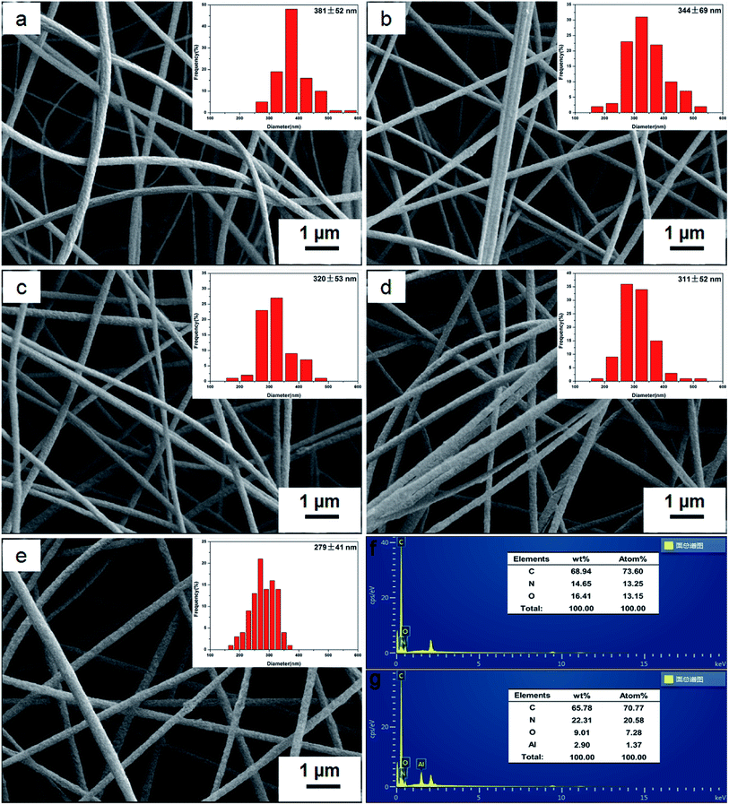
The morphologies of the various prepared electrospun nanofibrous PAN-based membranes were observed by SEM and shown in Fig. 1a–e. It can be seen that these membranes with unique 3D interconnected, highly uniform and porous structures were well formed by randomly oriented nanofibers, free of beads and droplets that would have a negative effect on the performance of the membranes. The insets of Fig. 1a–e depict the fiber diameter distributions of different membranes and the average fiber diameters of each sample are presented in Table 1. There is a slight decrease in average fiber diameter with the increase of BM content, which indicated that the introduction of BM helps to reduce fiber diameter. It may be ascribed to the increased viscosity, altering surface tension and changing electrostatic repulsion of the mix solution, confirmed by Shayapat et al.,37 who showed that introducing nano-SiO2 particles to PI matrix reduced the fiber diameter. Fig. 1f and g exhibit the EDX spectrum of the pure PAN and 30 wt% BM/PAN membranes respectively, indicating that BM was successfully embedded in composite nanofibers.| Membrane | Thickness (μm) | Fiber diameter (nm) | Porosity (%) | Electrolyte up-take (%) |
|---|---|---|---|---|
| PP | 25 | — | 52 | 112 |
| Pure PAN | 58 | 381 ± 52 | 82 | 760 |
| 10 wt% BM/PAN | 59 | 344 ± 69 | 84 | 815 |
| 20 wt% BM/PAN | 59 | 320 ± 53 | 86 | 854 |
| 30 wt% BM/PAN | 55 | 311 ± 52 | 88 | 1065 |
| 40 wt% BM/PAN | 53 | 279 ± 41 | 90 | 1149 |
3.2. Porosity and electrolyte up-take
The porosity of the battery separator is a significant factor determining how fast Li-ions transportation between the anode and cathode.11 Table 1 shows that the porosity of pure PAN membrane (82%) is much higher than that of PP membrane (52%) due to its unique 3D interconnected structure. Meanwhile, the porosities of BM/PAN membranes have a slight increase with the increased BM content, which may be ascribed to the change of fiber diameter.The electrolyte up-take is a vital parameter to evaluate the absorption capacity of the separator. The separator that absorbed and retained a large amount of liquid electrolyte will contribute to obtaining low internal resistance and high ionic conductivity. Results in Table 1 show the abilities of electrolyte up-take of the PP and BM/PAN membranes with different contents of BM. The electrolyte up-take of PP membrane is 112%, which is much lower than those of pure PAN and BM/PAN membranes owing to its hydrophobic nature and low porosity. Compared to the pure PAN membrane and BM/PAN membranes, there is an increase in electrolyte up-take with increased BM content. This is attributed to the high porosity of these PAN-based membranes and high affinity of BM to the liquid electrolyte.
3.3. FTIR and XRD analysis
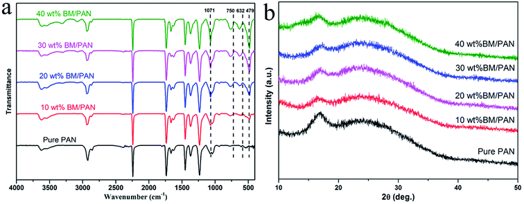
Fig. 2a shows the FTIR spectra of pure PAN and BM/PAN membranes with different amounts of BM content. For all membranes the absorption peaks at 2243 cm−1 correspond to the stretching vibration of the nitrile group. In the spectra of BM/PAN membranes, the bending vibration peak of 1071 cm−1 is assigned to the Al–O–H group, and the peaks near 750 cm−1, 632 cm−1, 479 cm−1 correspond to the twisting, stretching and bending vibrations of the Al–O group, indicating the existence of BM.38 Moreover, it can be observed that the intensities of these peaks representing the BM strengthen with the increasing content of BM, confirming that the relevant proportion of BM has been included in the membranes.Fig. 2b shows the XRD patterns of pure PAN and various BM/PAN membranes. In the XRD pattern of pure PAN nanofiber mat, the relatively sharp peak at 17° represents the crystalline part of PAN and a broad peak near 26° indicates the amorphous region of PAN nanofiber.39 The same peaks can also be seen in the XRD patterns of different BM/PAN membranes. With the increasing introduction of BM, the peaks at 17° become broader suggesting that the crystalline structure was disrupted and the amorphous region was increased. The increased amorphous region of the polymer matrix is favorable to enhance the electrolyte up-takes and ionic conductivities of the membranes.
3.4. Thermal stability
The thermal stability of the separator is a critical property for their long-time use during lithium ion battery operation.40 The thermal behavior of the PP, pure PAN and BM/PAN membranes was investigated by DSC and TG, as shown in Fig. 3a and b, respectively. From the DSC curves, the PP membrane possesses an endothermic peak centered at 166.8 °C corresponding to the melting point. The exothermic peaks corresponding to decomposition center at 298.7 °C for pure PAN membrane, while at 300.5, 303.1 and 313.2 °C for 10, 20 and 30 wt% BM/PAN membranes, respectively. It demonstrates that the addition of BM into the PAN nanofibers has a relatively higher decomposition temperature compared with the pure PAN nanofibers. The inclusion of ceramic particles can improve the thermal stability of the polymer matrix, also confirmed by the studies of Smith et al.39 and Ji et al.41 However, there is a decrease in the exothermic peak centered at 301.5 °C when the content of BM was up to 40 wt%. This may be ascribed to the decrease in air permeability. As the content of BM increased, air permeability would decrease. Therefore, the thermal stability of the polymer matrix did not change much or even decrease slightly. This means that there exists an appropriate loading for composite membrane. The DSC results show that the inclusion of BM can enhance the thermal stability of PAN matrix.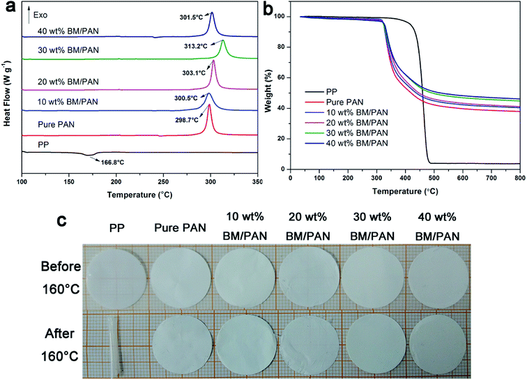 | ||
| Fig. 3 DSC curves (a), TG curves (b), and photographs before and after thermal treatment in the oven at 160 °C for 30 min (c) of various membranes. | ||
Fig. 3b shows the weight loss of PP, pure PAN and BM/PAN membranes. It can be seen that the PP membrane almost lost all its weight under the extreme temperature near 500 °C compared with the pure PAN and BM/PAN membranes. In addition, all the PAN-based samples exhibit only one weight loss step at ∼318 °C which corresponds to the degradation of PAN chains. The residual weights of various BM/PAN membranes increased along with the enhanced loading of BM in membranes. It indicates that the addition of BM particles can improve PAN-based membranes' thermal stability at high temperature.
Fig. 3c gives the photographs of the PP, pure PAN and BM/PAN membranes before and after thermal treatment at 160 °C for 30 min. It can be seen that the PP membrane suffered severe dimensional changes and shrank into a roll, while the pure PAN and BM/PAN membranes still maintained their original dimensions, demonstrating the higher thermal stability of PAN and BM/PAN membranes.
3.5. Mechanical properties
Adequate mechanical strength is vitally important for the separator to meet the battery assembly process. Fig. 4a shows the stress–strain curves of pure PAN and BM/PAN membranes. The tensile strength of pure PAN membrane is 6.51 MPa, while 10, 20, 30 and 40 wt% BM/PAN membranes are 10.35, 11.78, 11.5, 7.44 MPa, respectively, confirming that the introduction of BM contributes to enhancing the tensile strengths of BM/PAN membranes. Among these, 20 wt% BM/PAN membrane shows the highest tensile strength. However, when the BM content is up to 30 wt%, the tensile strength of the membrane begins to decrease and displays brittle behaviour owing to the high ceramic loading. Even so, the 30 wt% BM/PAN membrane still possesses good mechanical strength to satisfy the assembly process, which could be demonstrated after folding and winding tests shown in Fig. 4b and c. The 30 wt% BM/PAN membrane was folding several times without breaking and there was no mechanical fracture after winding a glass rod with a diameter of about 7 mm, indicating that it has superior flexibility and considerable mechanical strength.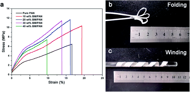 | ||
| Fig. 4 The stress–strain curves (a) of various membranes; folding (b) and winding (c) tests of 30 wt% BM/PAN composite nanofiber membrane. | ||
3.6. Ionic conductivity
Ionic conductivity is one of the most important properties for a separator to transport ions between anode and cathode during the operation of Li-ion batteries. The Nyquist plots of all the liquid electrolyte-soaked separators obtained by AC impedance measurement can be seen in Fig. 5. The intercept of the Nyquist plot at high-frequency on the real Z represents the bulk resistance (Rb), as shown in the inset of Fig. 5. According to eqn (3), the ionic conductivities of all the membranes were calculated and displayed in Table 2. The ionic conductivities are 1.27, 1.57, 1.66, 2.85 and 2.14 mS cm−1, respectively, for pure PAN and BM/PAN membranes with 10, 20, 30 and 40 wt% BM. Owing to the high porosity and electrolyte up-take of PAN nanofiber mat, its ionic conductivity is nearly 3 times higher than that of the PP membrane (0.41 mS cm−1). Moreover, the ionic conductivities increase as long as the content of the BM increases. Among these, the 30 wt% BM/PAN exhibits the highest ionic conductivity value of 2.85 mS cm−1, which is in agreement with the porosity and electrolyte up-take results.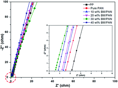 | ||
| Fig. 5 AC impedance spectra of SS|separator|SS cells assembled with various membranes (inset shows the plots at high frequency). | ||
| Membrane | Ionic conductivity (mS cm−1) |
|---|---|
| PP | 0.41 |
| Pure PAN | 1.27 |
| 10 wt% BM/PAN | 1.57 |
| 20 wt% BM/PAN | 1.66 |
| 30 wt% BM/PAN | 2.85 |
| 40 wt% BM/PAN | 2.14 |
3.7. Interfacial resistance
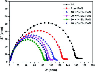
The compatibility between liquid electrolyte-soaked separator and lithium anode was determined by electrochemical impedance spectrum (EIS) of a Li|separator|Li cell. As is shown in Fig. 6, the semi-circular diameters in the high frequency zone indicate the interfacial resistance of liquid electrolyte-soaked separators and Li metal. The order of the interfacial resistance is: 30 wt% BM/PAN membrane (84 Ω) < 40 wt% BM/PAN membrane (92 Ω) < 20 wt% BM/PAN membrane (97 Ω) < 10 wt% BM/PAN membrane (108 Ω) < pure PAN membrane (127 Ω) < PP membrane (160 Ω). Obviously, the interfacial resistance of pure PAN and BM/PAN membranes are lower than that of the PP membrane. This result indicates the excellent interfacial compatibility of PAN and BM/PAN membranes with lithium anode, among which, the 30 wt% BM/PAN performed the best. Furthermore, BM/PAN membranes exhibit the lowest interfacial resistance values, which is consistent with the higher electrolyte up-takes of the BM/PAN membranes.3.8. Electrochemical stability
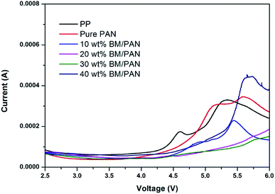
The electrochemical stability windows of the cells (SS|separator|Li) with various separators were carried out by linear sweep voltammetry (LSV). As shown in Fig. 7, the electrochemical stability window of the PP membrane is around 4.3 V vs. Li+/Li. It is evident that the pure PAN membrane and the BM/PAN membranes have higher electrochemical stability than the PP membrane, and their windows are over 4.5 V vs. Li+/Li, demonstrating that the BM/PAN membranes would be compatible with electrolytes and suitable for lithium ion batteries at high voltage. Among these, the 30 wt% BM/PAN membrane exhibits the widest electrochemical stability windows of 5.5 V vs. Li+/Li.3.9. Cycling performance
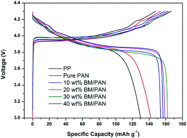
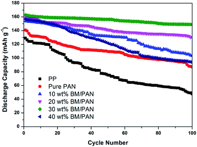
Fig. 8 gives the initial charge–discharge curves of Li/LiCoO2 cells containing BM/PAN membranes with different amounts of BM at 0.5C in the voltage range of 3.0–4.3 V. The initial discharge capacity for PP membrane is 129 mA h g−1, while the initial discharge capacity for pure PAN membrane is 141 mA h g−1. Furthermore, the initial discharge capacity increased with the introduction of BM into the PAN nanofiber membrane. The initial discharge capacity of 10, 20, 30, 40 wt% BM/PAN membranes are 153, 158, 162, 156 mA h g−1, respectively. The 30 wt% BM/PAN membrane shows the highest discharge capacity, which may be ascribed to the higher ionic conductivity.The cycling performance of Li/LiCoO2 cells using different separators was further examined under the constant charge/discharge rate of 0.5C for 100 cycles. As seen from Fig. 9, the discharge capacity decreases gradually as the cycle number increases. Obviously, the BM/PAN membranes display much better discharge capacity retention than the PP membrane (36.4%) and pure PAN membrane (61.0%). The cells with the 30 wt% BM/PAN membrane exhibit the largest capacity retention ratio of 90.7%, while the 10, 20 and 40 wt% BM/PAN membranes are 67.32%, 82.3% and 59.6%, respectively. These different results might be attributed to the various porosities, electrolyte up-takes and ionic conductivities of separators formed by different contents of BM.
3.10. C-rate performance
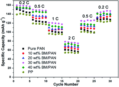
The rate capability of Li/LiCoO2 cells assembled with various membranes has also been studied at constant current charge/discharge rates from 0.2C to 2C and then back to 0.2C for each 5 cycles, shown in Fig. 10. In general, the discharge capacity of all cells gradually decreases with the increase in discharge current density. The initial specific capacity of the BM/PAN membranes was around 158 mA h g−1 at 0.2C higher than those of the pure PAN membrane and PP membrane, 150 mA h g−1 and 139 mA h g−1, respectively. As the current density increases to 2C, the BM/PAN membranes exhibit less capacity fading compared to the PP membrane. The rate retention rates are 39, 40, 42, 50 and 45% for pure PAN, 10, 20, 30 and 40 wt% BM/PAN cells at 2C, respectively. When the current density is brought back to 0.2C, the discharge capacity of the cells is almost recovered after 30 cycles. It demonstrates that the cells containing BM/PAN membranes can improve the rate performance, which can be ascribed to the high electrolyte up-takes and ionic conductivities of BM/PAN membranes. Particularly, the cell containing the 30 wt% BM/PAN membrane shows the largest discharge capacity values of 158, 150, 121, 79, 125, 142 mA h g−1 at different C-rates of 0.2, 0.5, 1, 2, 0.5 and 0.2C, respectively. The result indicates that the 30 wt% BM/PAN membrane is suitable for long-term lithium ion battery operation.3.11. A comparison with commercial membrane
As shown in the Table 3, compared with other commercial membranes, the 30 wt% BM/PAN membrane exhibits the highest porosity (88%) and ionic conductivity (2.85 mS cm−1), indicating an excellent ion transport efficiency, and the lowest interface resistance also reveals a superior interfacial compatibility. In addition, DSC analysis has been conducted to investigate the melting point of these membranes, and the 30 wt% BM/PAN membrane achieves a considerable melting point (313.2), higher than that of PE (130–150) and PP (166.8), suggesting an excellent thermal stability. Consequently, BM/PAN membrane shows a promising potential for the lithium-ion battery separator.| Membrane | Porosity (%) | Ionic conductivity (mS cm−1) | Melting point (°C) | Interfacial resistance (Ω) |
|---|---|---|---|---|
| PE | 44.6 | 0.71 | 130–150 | 282 |
| PI | 51.2 | 1.84 | 480 | 176 |
| PP | 52 | 0.41 | 166.8 | 160 |
| Pure PAN | 82 | 1.27 | 298.7 | 127 |
| 10 wt% BM/PAN | 84 | 1.57 | 300.5 | 108 |
| 20 wt% BM/PAN | 86 | 1.66 | 303.1 | 97 |
| 30 wt% BM/PAN | 88 | 2.85 | 313.2 | 84 |
| 40 wt% BM/PAN | 90 | 2.14 | 301.5 | 92 |
4. Conclusions
The BM/PAN membrane was successfully prepared via the electrospinning method. The BM/PAN membrane exhibits higher ionic conductivity and lower interfacial resistance than the PP membrane because of its higher porosity and larger electrolyte up-take. Moreover, the BM/PAN membrane shows attractive thermal stability under high temperature conditions and exhibits excellent cycling and rate performance of the cells. Particularly, batteries containing 30 wt% BM/PAN membranes possess the highest ionic conductivity (2.85 mS cm−1), widest electrochemical stability window (5.5 V vs. Li+/Li), leading to the highest initial discharge capacity (162 mA h g−1) and the largest capacity retention ratio (90.7%) at 0.5C after 100 cycles. Considering the advantages of the BM/PAN membrane, such kinds of designed BM/PAN membrane will be a promising separator for lithium ion batteries.Conflicts of interest
There are no conflicts to declare.Acknowledgements
The authors are very grateful for the financial support from the Natural Science Foundation of Guangdong Province (2016A030313475, China), the Dongguan Science and Technology Project (No. 201521510201, China) and the Project for Science and Technology of Guangdong Province (2015B010135009, China).References
- M. Armand and J. M. Tarascon, Nature, 2008, 451, 652–657 CrossRef CAS PubMed.
- H. Lee, M. Yanilmaz, O. Toprakci, K. Fu and X. Zhang, Energy Environ. Sci., 2014, 7, 3857–3886 RSC.
- D. Deng, Energy Sci. Eng., 2015, 3, 385–418 CrossRef.
- J. M. Tarascon and M. Armand, Nature, 2001, 414, 359–367 CrossRef CAS PubMed.
- P. Arora and Z. J. Zhang, Chem. Rev., 2004, 104, 4419–4462 CrossRef CAS PubMed.
- S. S. Zhang, J. Power Sources, 2007, 164, 351–364 CrossRef CAS.
- W. Xu, Z. Wang, L. Shi, Y. Ma, S. Yuan, L. Sun, Y. Zhao, M. Zhang and J. Zhu, ACS Appl. Mater. Interfaces, 2015, 7, 20678–20686 CrossRef CAS PubMed.
- Z. Wang, F. Guo, C. Chen, L. Shi, S. Yuan, L. Sun and J. Zhu, ACS Appl. Mater. Interfaces, 2015, 7, 3314–3322 CrossRef CAS PubMed.
- Y. Wang, S. Wang, J. Fang, L. Ding and H. Wang, J. Membr. Sci., 2017, 537, 248–254 CrossRef CAS.
- H. Jeon, D. Yeon, T. Lee, J. Park, M. Ryou and Y. M. Lee, J. Power Sources, 2016, 315, 161–168 CrossRef CAS.
- M. Kim, J. K. Kim and J. H. Park, Adv. Funct. Mater., 2015, 25, 3399–3404 CrossRef CAS.
- J. Y. Kim, Y. Lee and D. Y. Lim, Electrochim. Acta, 2009, 54, 3714–3719 CrossRef CAS.
- V. Aravindan, J. Sundaramurthy, P. Suresh Kumar, Y. Lee, S. Ramakrishna and S. Madhavi, Chem. Commun., 2015, 51, 2225–2234 RSC.
- J. Lee, C. Lee, K. Park and I. Kim, J. Power Sources, 2014, 248, 1211–1217 CrossRef CAS.
- H. Lee, J. M. Koo, D. Sohn, I. Kim and S. S. Im, RSC Adv., 2016, 6, 40383–40388 RSC.
- M. Zaccaria, D. Fabiani, G. Cannucciari, C. Gualandi, M. L. Focarete, C. Arbizzani, F. De Giorgio and M. Mastragostino, J. Electrochem. Soc., 2015, 162, A915–A920 CrossRef CAS.
- M. Yanilmaz, Y. Lu, J. Zhu and X. Zhang, J. Power Sources, 2016, 313, 205–212 CrossRef CAS.
- Z. Li, W. Wang, Y. Han, L. Zhang, S. Li, B. Tang, S. Xu and Z. Xu, J. Power Sources, 2018, 378, 176–183 CrossRef CAS.
- M. Yanilmaz, J. Zhu, Y. Lu, Y. Ge and X. Zhang, J. Mater. Sci., 2017, 52, 5232–5241 CrossRef CAS.
- Y. Miao, G. Zhu, H. Hou, Y. Xia and T. Liu, J. Power Sources, 2013, 226, 82–86 CrossRef CAS.
- X. Ma, P. Kolla, R. Yang, Z. Wang, Y. Zhao, A. L. Smirnova and H. Fong, Electrochim. Acta, 2017, 236, 417–423 CrossRef CAS.
- G. Zainab, X. Wang, J. Yu, Y. Zhai, A. Ahmed Babar, K. Xiao and B. Ding, Mater. Chem. Phys., 2016, 182, 308–314 CrossRef CAS.
- S. Park, Y. Jung, W. Shin, K. H. Ahn, C. H. Lee and D. Kim, J. Membr. Sci., 2017, 527, 129–136 CrossRef CAS.
- Y. Liu, X. Peng, Q. Cao, B. Jing, X. Wang and Y. Deng, J. Phys. Chem. C, 2017, 121, 19140–19146 CrossRef CAS.
- A. K. Solarajan, V. Murugadoss and S. Angaiah, J. Appl. Polym. Sci., 2017, 134, 45177 CrossRef.
- W. Shin and D. Kim, J. Power Sources, 2013, 226, 54–60 CrossRef CAS.
- X. Zhu, X. Jiang, X. Ai, H. Yang and Y. Cao, J. Membr. Sci., 2016, 504, 97–103 CrossRef CAS.
- X. Liang, Y. Yang, X. Jin, Z. Huang and F. Kang, J. Membr. Sci., 2015, 493, 1–7 CrossRef CAS.
- W. Xiao, J. Liu and C. Yan, Chem. Phys. Lett., 2017, 686, 134–139 CrossRef CAS.
- S. A. Smith, S. A. Smith, J. H. Park, J. H. Park, B. P. Williams, B. P. Williams, Y. L. Joo and Y. L. Joo, J. Mater. Sci., 2017, 52, 3657–3669 CrossRef CAS.
- J. Cho, Y. Jung, Y. S. Lee and D. Kim, J. Membr. Sci., 2017, 535, 151–157 CrossRef CAS.
- B. Sun, X. Li, R. Zhao, M. Yin, Z. Wang, Z. Jiang and C. Wang, J. Taiwan Inst. Chem. Eng., 2016, 62, 219–227 CrossRef CAS.
- K. Feng, D. Rong, W. Ren and X. Wen, Mater. Express, 2015, 5, 371–375 CrossRef CAS.
- C. Yang, H. Tong, C. Luo, S. Yuan, G. Chen and Y. Yang, J. Power Sources, 2017, 348, 80–86 CrossRef CAS.
- R. Xu, R. Xu, X. Lin, X. Lin, X. Huang, X. Huang, J. Xie, J. Xie, C. Jiang, C. Jiang, C. Lei and C. Lei, J. Solid State Electrochem., 2018, 22, 739–747 CrossRef CAS.
- G. Zhong, Y. Wang, C. Wang, Z. Wang, S. Guo, L. Wang, X. Liang and H. Xiang, Ionics, 2019, 25, 2677–2684 CrossRef CAS.
- J. Shayapat, O. H. Chung and J. S. Park, Electrochim. Acta, 2015, 170, 110–121 CrossRef CAS.
- H. Hou, Y. Xie, Q. Yang, Q. Guo and C. Tan, Nanotechnology, 2005, 16, 741–745 CrossRef CAS.
- S. A. Smith, B. P. Williams and Y. L. Joo, J. Membr. Sci., 2017, 526, 315–322 CrossRef CAS.
- H. Zhang, J. Liu, M. Guan, Z. Shang, Y. Sun, Z. Lu, H. Li, X. An and H. Liu, ACS Sustainable Chem. Eng., 2018, 6, 4838–4844 CrossRef CAS.
- L. Ji and X. Zhang, Mater. Lett., 2008, 62, 2161–2164 CrossRef.
| This journal is © The Royal Society of Chemistry 2020 |


