
 Open Access Article
 This Open Access Article is licensed under a Creative Commons Attribution-Non Commercial 3.0 Unported Licence
Photocatalytic degradation of methylene blue by a cocatalytic PDA/TiO2 electrode produced by photoelectric polymerization
Zehui Guoa,
Guoqing Wang *a,
Haiqing Fua,
Peiqing Wangb,
Jianhe Liaoa and
Aimin Wanga
*a,
Haiqing Fua,
Peiqing Wangb,
Jianhe Liaoa and
Aimin Wanga
aState Key Laboratory of Marine Resource Utilization in South China Sea, School of Materials Science and Engineering, Hainan University, No. 58, Renmin Avenue, Haikou 570228, P. R. China. E-mail: 13208916675@163.com; 1359650458@qq.com; 990359@hainanu.edu.cn; aimwang@163.com; wangguoqing@hainanu.edu.cn; Tel: +86-898-31670103
bSichuan Sunvea New Materials Co., Ltd., GuangAn, 638500, China. E-mail: 13817849388@163.com
First published on 10th July 2020
Abstract
This study reports a new method for photocatalysts to degrade organic dyes on organic semiconductors. A novel strategy is reported to form TiO2 nanorod (NR)/polydopamine (PDA) electrodes with a photoelectric polymerization strategy for PDA (pep-PDA) to produce cocatalytic electrodes. Amperometric i–t curves and UV-vis diffuse reflectance spectra were recorded and showed that compared with traditional self-polymerization (sp-PDA) and electropolymerization (ep-PDA), TiO2 NR/pep-PDA exhibited an enhanced photocatalytic activity under visible light. As expected, TiO2 NR/pep-PDA showed a significant improvement for the degradation of methylene blue (MB) under visible light, which can be attributed to the strong absorption of PDA in the visible light region and the more complete and uniform coverage of the TiO2 NRs by the pep-PDA film. This study not only proposes a novel and highly efficient way to load PDA on TiO2 NRs but also provides useful insights for the loading of other photocatalysts on organic semiconductors to degrade organic dyes.
Introduction
Currently, a shortage of global fresh water resources and a deterioration of water quality have become universal problems.1,2 An urgent need for clean water resources has led to a continuous development of advanced water-treatment technologies. There are many advanced physical and chemical technologies for water pollution treatment, such as adsorption, filtration, reverse osmosis, electrocatalysis, and photocatalysis.3–7 However, these methods have their own limitations, such as high energy consumption and incomplete processing.8 Fortunately, the increase in research on conductive polymer nanomaterials has presented the possibility for catalysis and adsorption to be applied together in water treatment.9,10In recent years, semiconductor photocatalytic technology has shown great potential in water treatment as an environmentally friendly, stable, and inexpensive treatment method.11 Rutile TiO2 nanorod arrays (NRs) are widely used as semiconductor catalysts with high catalytic activity and thermodynamic stability.12–14 However, the wide band gap (3.02 eV) of rutile TiO2 means it only works under high-energy (UV) light, which is not conducive to the economic viability of the material. Polydopamine (PDA) is a highly effective sensitizer that can significantly improve the photocatalytic activity of rutile TiO2 under visible light.15,16 In addition, the PDA coating has also proven to be an excellent adsorbent for methylene blue (MB).17 The methods for forming a PDA coating on TiO2 NRs include water bath self-polymerization,10 electrochemical polymerization,18 and photopolymerization.15 However, we found in experiments that self-polymerization and electrochemical polymerization produced nonuniform PDA coatings on the TiO2 NR surfaces, which was not conducive to MB adsorption and degradation. Furthermore, traditional PDA photopolymerization requires at least 6 h to uniformly cover the surface of TiO2 NRs, which is not useful when searching for a rapid and inexpensive synthesis of the required materials.
Based on these considerations, we report a method to induce the uniform polymerization of PDA on the surface of TiO2 by constructing a photoelectrocatalytic system. By introducing UV light into the traditional electropolymerization process, the PDA could evenly cover the surface of TiO2 NRs in 1 h under a bias voltage of 0.2 V, which is 6 times shorter than the traditional photopolymerization time. As expected, compared to self-polymerization (sp-PDA) and electropolymerization (ep-PDA), synergistic photoelectric co-catalysis polymerization PDA (pep-PDA) on the TiO2 NR surface has a higher adsorption capacity and stronger catalytic performance for MB. This synergistic method for the photoelectric co-catalysis polymerization of PDA can not only quickly form a film on the surface of a semiconductor material but can also cover the electrode surface uniformly and completely. This provides potential for the industrial applications of TiO2 NR/pep-PDA in the photocatalytic degradation of organic dyes.
Experiment
Preparation of rutile TiO2 NRs
Before the hydrothermal reaction started, half of the area of the FTO was wrapped with green tape and then sequentially sonicated for 20 min in isopropyl alcohol, acetone, ethanol, and pure water. Next, 10 mL of pure water, 10 mL of hydrochloric acid (12 M), and 1 mL of titanium isopropoxide were placed in a beaker and stirred for 60 min to form a TiO2 precursor solution. Subsequently, the stirred precursor solution and the processed FTO were transferred to a reaction kettle and hydrothermally treated at 160 °C for 200 min. After the reaction was cooled to room temperature, the FTO samples in the reaction kettle were collected and sequentially washed with acetone, ethanol, and pure water. Then, they were dried at room temperature. Finally, the dried samples were placed in a muffle furnace and annealed at 550 °C for 180 min at a temperature increasing rate of 2.5 °C min−1.Preparation of the TiO2 NR/pep-PDA electrode
PDA was uniformly and completely grown on the surface of the TiO2 NRs by introducing light during the electropolymerization (bias 0.2 V) process. Briefly, 400 mg of a dopamine (DA) hydrochloride solution was added to 100 mL of PBS (pH = 6.0) solution as an electrolytic solution. In a quartz glass beaker, a three-electrode system (Pt counter electrode and Ag/AgCl reference electrode; Zahner Zennium, Germany) was used to simulate the electropolymerization environment, and the working electrode was irradiated with a low-power UV light (30 W, 365 nm) source for 60 min. To facilitate comparisons, a self-polymerized (90 °C, 240 min) TiO2 NR/sp-PDA electrode and an electropolymerized (0.8 V, 60 min) TiO2 NR/ep-PDA electrode were prepared with the same content of dopamine hydrochloride.Adsorption of methylene blue
The prepared TiO2 NR/pep-PDA electrode and 30 mL of an MB solution (0.1 mg mL−1) were put into a beaker and stirred at a low speed for 360 min in darkness. The MB concentration in the supernatant was measured every 60 min using a UV-visible spectrophotometer. The initial absorbance was expressed as C0, and the absorbance during the adsorption process was expressed as C, so (C0 − C)/C0 could approximate the adsorption efficiency. In addition, the TiO2 NRs, TiO2 NR/sp-PDA, and TiO2 NR/ep-PDA electrodes were tested for absorbance by the same method. The above experiments were performed three times to evaluate the error of the experimental data.Photocatalytic degradation of methylene blue
The prepared TiO2 NR/pep-PDA electrode and 30 mL of the MB solution were placed in a round Petri dish and exposed to visible light (420–780 nm) under vertical irradiation for 180 min. The MB concentration in the supernatant was measured every 30 min using a UV-visible spectrophotometer. The initial absorbance was expressed as V0, and the absorbance during the adsorption process was expressed as V, so (V0 − V)/V0 could approximate the degradation efficiency. In addition, the TiO2 NRs, TiO2 NR/sp-PDA, and TiO2 NR/ep-PDA electrodes were tested for absorbance by the same method. The above experiments were performed three times to evaluate the error of the experimental data.Results and discussion
Preparation and characterization
The preparation process of the TiO2 NR/pep-PDA is shown in Fig. 1. According to the previously reported classical method,19 TiO2 NRs were grown on FTO by a hydrothermal reaction using titanium isopropoxide hydrochloride as a precursor. The washed and calcined TiO2 NR electrodes were placed in an oven to dry. Then, the prepared TiO2 NR electrode was placed in a DA solution (quartz beaker, pH = 6.0) and connected to a Pt electrode and a reference electrode through an electrochemical workstation. After the electropolymerization system was set up, the voltage was set to 0.2 V and low-power UV light was used to irradiate the conductive surface of the electrode. It is known that TiO2 NR electrodes can generate a large number of holes and electrons under UV light. However, due to the high photoelectric recombination efficiency, the actual number of holes and electrons is much lower than the theoretical value, which results in a low efficiency of photopolymerized PDA. Fortunately, when an electrical circuit is introduced during photopolymerization, a large amount of holes will be left on the surface of the TiO2 NR electrode because electrons are transported to the counter electrode; thus, the above improves the polymerization efficiency of PDA.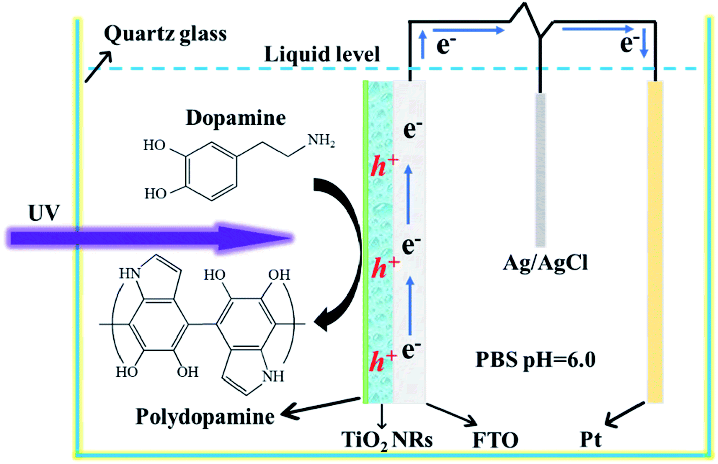 | ||
| Fig. 1 Schematic of the photoelectrocatalytic polymerization of PDA on the surface of the TiO2 NR electrode. | ||
To investigate the uniformity of the PDA films formed by different polymerization methods, all the electrodes were characterized by SEM. Fig. 2(a) shows a top-view SEM image of the TiO2 NRs, Fig. 2(b) shows a side-view SEM image of the TiO2 NRs. TiO2 showed a regular nanorod array structure, and the membrane structure was not found on the surface. Fig. 2(c) shows the SEM image of the TiO2 NR/sp-PDA. The PDA film was irregular on the surface of the TiO2 NRs and was not well distributed because DA preferentially grows where the PDA aggregates during self-polymerization.20 As shown in Fig. 2(d), the electropolymerized PDA films were stratiform and relatively more distributed on the surface of the TiO2 NRs compared to those prepared with the self-polymerization method. The potentials on the surface of the TiO2 NR electrode were different after being energized, which was caused by the crystallinity and size difference between each nanorod.21 Fig. 2(e) shows an SEM image of the TiO2 NR/pep-PDA electrode. Unlike sp-PDA and ep-PDA, the pep-PDA film was evenly distributed on the surfaces of the TiO2 NRs. The combination of light and electricity caused a large number of holes to accumulate on the surface of each TiO2 NRs. These photogenerated holes decomposed water to generate a large number of free radicals, thereby initiating the highly efficient polymerization of DA. In addition, the reason for the different thicknesses of the PDA film is that each nanorod was different from each other, so the catalytic efficiency of each place of the nanorod array was also different. To further demonstrate that the PDA film was effectively loaded on the surface of the TiO2 NRs, EDS mapping characterization of the TiO2 NR/pep-PDA (Fig. 2(e) white dotted area) was performed (Fig. 2(f)). Large and uniform amounts of C and N were distributed around Ti and O, which proved that the PDA film was uniformly loaded on the surface of the TiO2 NRs.
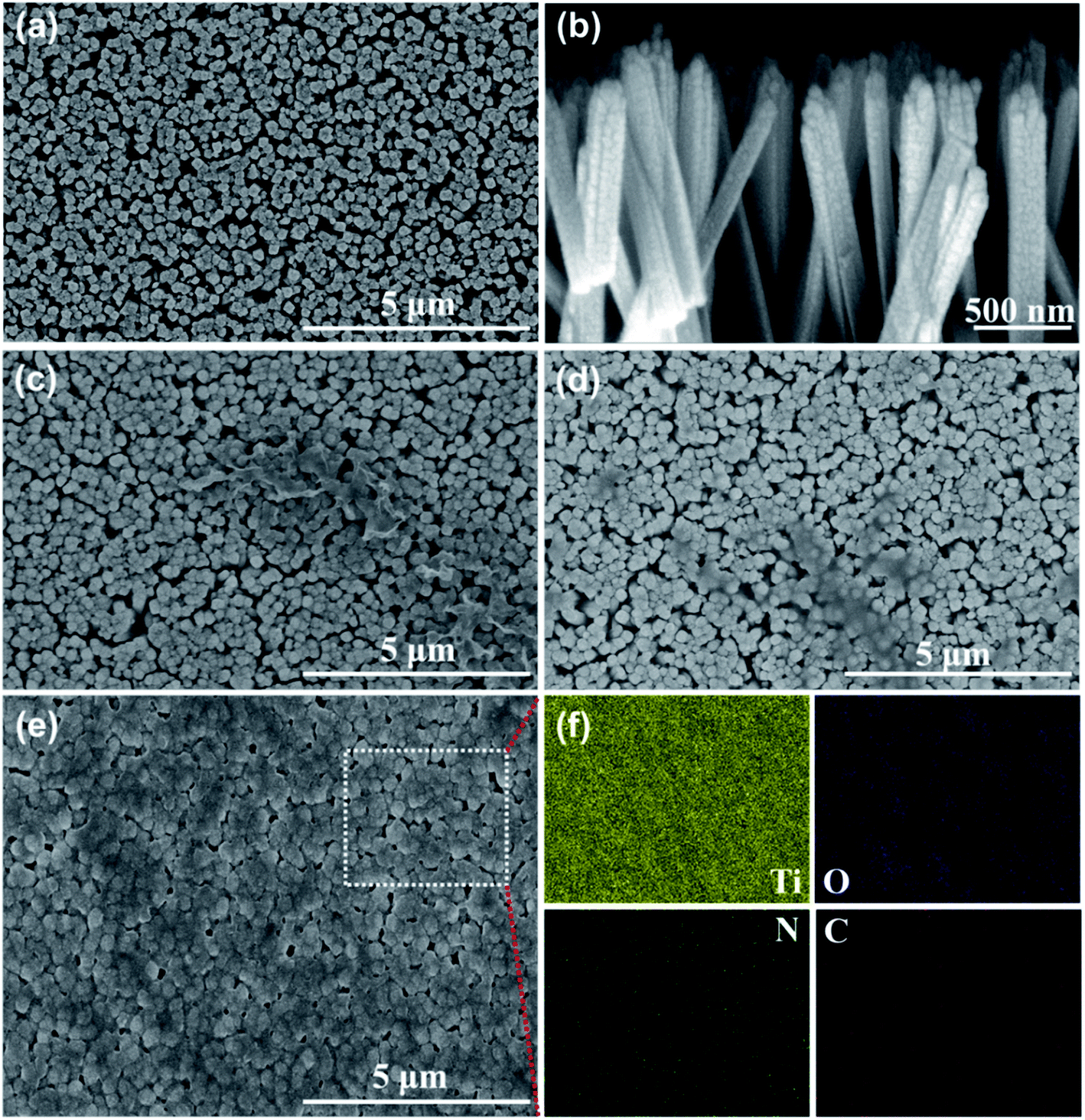 | ||
| Fig. 2 Top-view SEM images of: (a) TiO2 NRs, (c) TiO2 NR/sp-PDA, (d) TiO2 NR/ep-PDA, and (e) TiO2 NR/pep-PDA. Side-view SEM images of (b) TiO2 NRs. EDS mapping image of (f) TiO2 NR/pep-PDA. | ||
Based on previous reports investigating the effect of the PDA layer on the roughness of TiO2, we expected that the roughness of our synthesized TiO2 NR/pep-PDA would be lower than that of TiO2 NRs. The successful loading of PDA could significantly improve the roughness of materials with uneven structures. The AFM images of TiO2 NRs (Fig. 3(a–c)) and TiO2 NR/pep-PDA (Fig. 3(d–f)) and the roughness evaluation data are shown in Fig. 3. It can be easily seen from Fig. 3(a and d) that the electrode roughness after loading the PDA was significantly reduced. Fig. 3(c and f) show the roughness data of the electrode, where TiO2 NR/pep-PDA was much smaller than TiO2 NRs, which shows the uniform loading of the PDA on the electrode surface.
 | ||
| Fig. 3 3D, 2D images and height profile of the TiO2 NRs (a–c) and TiO2 NR/pep-PDA (d–f) electrode generated from atomic force microscopy (AFM) analysis. | ||
Comparison of the catalytic activities of the TiO2 NR/PDA electrodes under different polymerization conditions
Fig. 4(a) shows the XRD patterns of the TiO2 NR/PDA electrodes under different polymerization conditions. All the peaks in Fig. 4(a) are typical peaks of rutile TiO2 (PDF#21-1276) and FTO (PDF#46-1088), which shows that the polymerization mode of PDA did not affect the TiO2 NRs and did not introduce other impurities. The catalytic effect comes from the TiO2 NRs and PDA. After 6 cycles of degradation, the crystal form and peak intensity of TiO2 did not change much, indicating the stability of the TiO2 NR/pep-PDA electrode. | ||
| Fig. 4 (a) XRD patterns of the TiO2 NR/PDA electrodes under different polymerization conditions and after degradation. (b) UV-vis diffuse reflection spectra and (c) amperometric i–t curve responses of the TiO2 NR/PDA electrodes under different polymerization conditions. (d) Electrochemical impedance spectroscopy (Nyquist plots) of TiO2 NRs and TiO2 NR/pep-PDA in the light. (e) Photoluminescence (PL) spectra under 280 nm excitation at room temperature. (f) PL decay spectra of TiO2 NRs and TiO2 NR/pep-PDA. | ||
UV-vis diffuse reflectance spectroscopy was applied to analyze the photoelectric response characteristics of the TiO2 NR/PDA electrodes under different polymerization conditions. As shown in Fig. 4(b), pure TiO2 had edge absorption at wavelengths lower than 420 nm. Compared with pure TiO2, the spectra of TiO2 NR/sp-PDA and TiO2 NR/ep-PDA were enhanced in the visible region, which was attributed to the strong absorption of PDA in the visible region.22–24 Compared with TiO2 NRs/sp-PDA, the spectrum of TiO2 NR/ep-PDA was significantly enhanced in the visible light region, which may be due to it having a more regular morphology and a more appropriate degree of PDA polymerization. It is worth noting that the spectrum of TiO2 NR/pep-PDA had the strongest absorption in the visible light region, and the absorption band edge had a significant redshift, which indicates that pep-PDA plays a vital role in improving the visible light utilization of TiO2 NRs.
To further understand the photocatalytic activity advantages of the TiO2 NR/pep-PDA electrodes, instant photocurrent measurements of the electrodes prepared with different polymerization methods were obtained by irradiation with visible light. Fig. 4(c) shows the amperometric i–t curve responses of the different electrodes. The photocatalytic activity essentially corresponds to the magnitude of the photocurrent.11,25,26 This is because the essence of photocatalysis is a redox reaction that is initiated by holes or electrons on a photoactive surface.27,28 Therefore, to a certain extent, a high photocurrent can also represent an increase in catalytic activity. As seen from Fig. 4(c), the photocurrent of the TiO2 NR/pep-PDA electrode was much larger than that of the other electrodes, even 10 times that of pure TiO2. Therefore, pep-PDA was the most effective method for PDA loading.
As shown in Fig. 4(d), the prepared TiO2 NR/pep-PDA electrodes were characterized via EIS measurement, which is a powerful strategy for detecting photoelectrons and the electron–hole separation efficiency, as well as the charge-transfer resistance of TiO2 NR/pep-PDA electrodes. The radius of the semicircle in the EIS Nyquist plot was similar to the Rct of the fabricated biosensor. Compared with the TiO2 NRs, the TiO2 NR/pep-PDA electrodes exhibited a smaller semicircle radius, higher charge-transfer efficiency, and lower Rct in the same frequency range in the presence of light.29
Photoluminescence (PL) emission spectroscopy, which measures the irradiative recombination of electrons and holes, is a useful method to elucidate the migration and separation behavior of charge carriers in photocatalysts. We therefore measured the PL spectra for both TiO2 NRs and TiO2 NR/pep-PDA. The TiO2 NR spectrum showed an intense and wide emission peak at about 450 nm (Fig. 4(e)). Compared to TiO2 NRs, the PL emission intensity of TiO2 NR/pep-PDA was much lower, indicating the increased charge separation and transfer in TiO2 NR/pep-PDA.
In order to prove that the PDA introduced in TiO2 could promote the separation of photogenerated electrons and holes, the photogenerated electron lifetimes of the two electrodes were analyzed by time-resolved fluorescence spectroscopy (Fig. 4(f)). The fluorescence decay kinetics indicated that TiO2 NR/pep-PDA had a longer average fluorescence lifetime, while the significantly increased average fluorescence lifetime indicated that the presence of PDA could effectively promote the separation of photogenerated electrons and holes.
MB adsorption efficiency of the TiO2 NR/PDA electrodes prepared with different polymerization methods
Adsorption is also a method for treating organic pollutants. Good adsorption can assist the photoelectrode in degrading organic pollutants. Therefore, the TiO2 NR/PDA electrodes produced with different polymerization methods were tested for their MB adsorption efficiency in solution. Fig. 5(a) shows the MB adsorption efficiencies of the different electrodes. It can be easily observed that the MB adsorption efficiency on the adsorbent increased rapidly in the initial stage, but then, the subsequent growth rate gradually slowed down. This result can be attributed to the fact that in the initial stage, the adsorbent has a large number of surplus adsorption sites, so it can quickly adsorb a large number of MB molecules. Then, over time, the number of adsorption sites decreases, and MB molecules on the adsorbent will also repel free MB molecules in the solution. The experimental results are thus the same as expected. The TiO2 NR/pep-PDA electrode with a large area of PDA had the highest adsorption efficiency compared to that of the other two electrodes at the same time. | ||
| Fig. 5 (a) Adsorption efficiency of different electrodes in MB solution. (b) MB adsorption PL spectra of TiO2 NRs/pep-PDA under visible light irradiation. (c) Histogram of the adsorption efficiency at 360 min. (d) Degradation efficiency of different electrodes to MB solution. (e) MB degradation PL spectra of TiO2 NR/pep-PDA under visible light irradiation. (f) Histogram of the adsorption efficiency at 180 min. | ||
MB degradation efficiencies of the TiO2 NR/PDA electrodes prepared with different polymerization methods
Fig. 5(d) shows the visible light catalytic performance of the four different electrode materials for MB. The TiO2 NR/pep-PDA electrode, in the absence of a cocatalyst, showed enhanced visible light catalytic performance for MB, and the degradation efficiency reached 76% in 180 min. Compared with the other three electrodes, the degradation rate of TiO2 NR/pep-PDA was stable, and there was no rapid growth in the early stage or slow growth in the late stage. The reason for this may be that the degradation efficiency was limited by the electrode area.30,31 In addition, with increasing time, the degradation efficiency of TiO2 NR/ep-PDA began to decrease compared to that of TiO2 NR/sp-PDA after 75 min. The reason for the above reverse trend may be that the TiO2 NR/ep-PDA electrode had poor diffusibility in low-concentration MB solutions.Considering that long-term cycle durability is one of the most important properties of photocatalysts, a stability evaluation of the TiO2 NR/pep-PDA electrode was performed. As shown in Fig. 6(a), after 6 cycles and up to 1080 min of measurement, the TiO2 NR/pep-PDA electrode still retained 81% of its catalytic performance when compared to the first cycle, which indicated that the prepared electrode had high stability. TiO2 is a light and stable material, which can ensure that the catalytic ability does not significantly decrease after long-term light exposure.32–34 Similarly, benefitting from the pep-PDA polymerization method, the uniform loading of PDA on the surface of TiO2 is also one of the reasons for the overall performance of the stable material. Therefore, the photoelectrocatalytic polymerization of PDA is a promising method.
 | ||
| Fig. 6 (a) Measurement of the 6-cycle durability of the TiO2 NR/pep-PDA electrode to MB solution. (b) Histogram of the adsorption efficiency at 180 min. (c) Photocatalytic mechanism of the TiO2 NR/pep-PDA electrode to MB under visible light. (d) Effect of some scavengers on the photodegradation of MB. (e) Effect of hydroxyl radicals on the MB degradation of the TiO2 NR/pep-PDA electrode. (f) Universality of the TiO2 NR/pep-PDA electrode for the degradation of organic pollutants. | ||
At present, it is generally accepted that the mechanism of degrading organic pollutants is that the free radicals generated by the photocatalytic decomposition of water react with the target molecules. Therefore, the presence of H2O2 is beneficial to the photocatalytic degradation process because it can be reduced by photogenerated electrons to increase the rate of free radical formation. In addition, the consumption of photogenerated electrons by H2O2 reduces the recombination rate of electron holes and further improves the catalytic activity of the electrode itself (Fig. 6(c)).
To understand the photocatalytic degradation mechanism and the active species involved in the degradation of MB, trapping experiments using various scavengers were investigated. The prepared TiO2 NRs/pep-PDA catalyst was used to degrade MB after the incorporation of different scavengers. Fig. 6(d) shows that after the addition of KI and KBrO3, a dramatic decrease in the photodegradation efficiency was observed, indicating that both holes and electron plays a crucial role in the degradation of MB. In addition, we further studied the effect of the addition of H2O2 (5 mM) on the degradation efficiency. As shown in Fig. 6(e), the final degradation efficiency of the TiO2 NR/pep-PDA electrode under visible light was 75.6%, while the degradation efficiency reached 88.2% after adding H2O2. This result shows that H2O2 can effectively improve the degradation rate and efficiency of photocatalysts for organic pollutants.
In order to verify the universality of the prepared electrode A, catalytic degradation experiments were carried out on methylene orange (MO), Congo red dye (CR), and ofloxacin (OFX) respectively. Fig. 6(f) shows the visible light catalytic performance of the four different electrode materials for MB, MO, CR, and OFX. The TiO2 NR/pep-PDA electrode demonstrated enhanced visible light catalytic performance for MB, MO, CR, and OFX, and the degradation efficiency reached more than 73% in 180 min. It is worth noting that the degradation efficiency of organic dyes by electrode A was greater than for antibiotics, which shows that the prepared electrode was more suitable for the treatment of water pollution.
Conclusions
In summary, we successfully developed a new photoelectric polymerization strategy for PDA (pep-PDA) to quickly construct cocatalytic TiO2 NR/pep-PDA electrodes. Compared with the TiO2 NR/self-polymerization (sp-PDA) and TiO2 NR/electropolymerization (ep-PDA) electrodes, the TiO2 NR/pep-PDA electrode had a uniform and complete PDA film, and it exhibited high efficiency in conveniently degrading MB. The enhanced photocatalytic degradation ability was attributed to the surface of the TiO2 NRs being loaded with a more complete and uniform PDA film. In addition, the presence of H2O2 could effectively improve the degradation rate and efficiency of the photocatalysts to organic pollutants, which was attributed to the fact that H2O2 as an electron acceptor could not only improve the photocatalytic activity of the electrode but could also increase the rate of free radical generation. This study provides a new strategy for PDA loading on photocatalysts, and TiO2 NR/pep-PDA has the potential to be applied in industrial wastewater treatments.Conflicts of interest
The authors declare that there were no conflicts of interest.Acknowledgements
This work was financially supported by the National Natural Science Foundation of China (51963008) and the Horizontal Projects (zzzz002023317 and zzzz002023451). This study was also supported by the Analysis and Testing Center of Hainan University.References
- M. Hall-Spencer, R. Rodolfo-Metalpa and S. Martin, et al., Nature, 2008, 454(7200), 96–99 CrossRef PubMed
.
- D. Jiang, Y. Zhang and X. Li, Nanoscale, 2017, 9(34), 12348–12352 RSC
- S. Wang, Y. Boyjoo, A. Choueib and Z. H. Zhu, Water Res., 2005, 39(1), 129–138 CrossRef CAS PubMed
- S. T. Nejad, A. A. Shahrnoy, A. R. Mahjoub, N. E. Saloumahaleh and Z. Khazaee, Environ. Sci. Pollut. Res., 2018, 25(10), 9969–9980 CrossRef PubMed
- A. H. C. Khavar, G. Moussavi, A. R. Mahjoub, M. Satari and P. Abdolmaleki, Chem. Eng. J., 2018, 345, 300–311 CrossRef CAS
- H. Fakhri, A. R. Mahjoub and H. Aghayan, J. Nanostruct., 2017, 7, 223–235 CAS
- J. Cao, B. Xu, H. Lin, B. Luo and S. Chen, Chem. Eng. J., 2012, 185–186, 91–99 CrossRef CAS
- M. S. Sajab, C. H. Chia, S. Zakaria and P. S. Khiew, Bioresour. Technol., 2013, 128, 571–577 CrossRef CAS PubMed
- K. Ai, Y. Liu, C. Ruan, L. Lu and G. M. Lu, Adv. Mater., 2013, 25(7), 998–1003 CrossRef CAS PubMed
- W. X. Mao, X. J. Lin and W. Zhang, et al., Chem. Commun., 2016, 52(44), 7122–7125 RSC
- M. N. Chong, B. Jin, C. W. Chow and C. Saint, Water Res., 2010, 44(10), 2997–3027 CrossRef CAS PubMed
- X. Wang, H. Wang and H. Zhang, et al., ACS Energy Lett., 2018, 3(5), 1159–1164 CrossRef CAS
- J. Schneider, M. Matsuoka and M. Takeuchi, et al., Chem. Rev., 2014, 114(19), 9919–9986 CrossRef CAS PubMed
- R. Li, Y. Weng and X. Zhou, et al., Energy Environ. Sci., 2015, 8(8), 2377–2382 RSC
- Y. Liu, K. Ai and L. Lu, Chem. Rev., 2014, 114(9), 5057–5115 CrossRef CAS PubMed
- W. Yang, W. Xu, N. Zhang, X. Lai, J. Peng, Y. Cao and J. Tu, J. Mater. Sci., 2020, 55, 6105–6117 CrossRef CAS
- J. Fu, Z. Chen and M. Wang, et al., Chem. Eng. J., 2015, 259, 53–61 CrossRef CAS
- S. Y. Lee, S. Y. Lim, D. Seo and J.-Y. Lee, Adv. Energy Mater., 2016, 6(11), 1502207 CrossRef
- X. Li, J. Yu and M. Jaroniec, Chem. Soc. Rev., 2016, 45(9), 2603–2636 RSC
- F. Bernsmann, V. Ball and F. Addiego, et al., Langmuir, 2011, 27(6), 2819–2825 CrossRef CAS PubMed
- J. Cai, J. Huang and M. Ge, et al., Small, 2017, 13(19), 1604240 CrossRef PubMed
- H. Cheng, M. Hu, Q. Zhai, S. Li and Y. Jiang, Chem. Eng. J., 2018, 347, 703–710 CrossRef CAS
- J. Cai, J. Huang and Y. Lai, J. Mater. Chem. A, 2017, 5(31), 16412–16421 RSC
- Y. Wei, J. Kong and L. Yang, et al., J. Mater. Chem. A, 2013, 1(16), 5045–5052 RSC
- X. Chen, S. Shen and L. Guo, Chem. Rev., 2010, 110(11), 6503–6570 CrossRef CAS PubMed
- H. Tong, S. Ouyang, Y. Bi, N. Umezawa, M. Oshikiri and J. Ye, Adv. Mater., 2012, 24(2), 229–251 CrossRef CAS PubMed
- G. Williams, B. Seger and P. V. Kamat, ACS Nano, 2008, 2(7), 1487–1491 CrossRef CAS PubMed
- T. Hisatomi, J. Kubota and K. Domen, Chem. Soc. Rev., 2014, 43(22), 7520–7535 RSC
- W. Yang, X. Wang, W. Hao, Q. Wu, J. Peng, J. Tu and Y. Cao, J. Mater. Chem. B, 2020, 8, 2363–2370 RSC
- R. Asahi, T. Morikawa, T. Ohwaki, K. Aoki and Y. Taga, Science, 2001, 293(5528), 269–271 CrossRef CAS PubMed
- S. Liu, J. Yu and M. J. Fu, J. Am. Chem. Soc., 2010, 132(34), 11914–11916 CrossRef CAS PubMed
- M. Pelaez, N. T. Nolan and S. C. Pillai, et al., Appl. Catal., B, 2012, 125, 331–349 CrossRef CAS
- X. Chen and S. S. Mao, Chemlnform, 2007, 38(41), 9 Search PubMed
- X. Chen, L. Liu, P. Y. Yu and S. S. Mao, Science, 2011, 331(6018), 746–750 CrossRef CAS PubMed
| This journal is © The Royal Society of Chemistry 2020 |