
 Open Access Article
 This Open Access Article is licensed under a Creative Commons Attribution-Non Commercial 3.0 Unported Licence
High Eu3+ concentration quenching in Y3TaO7 solid solution for orange-reddish emission in photonics†
Fernanda Hediger Borgesa,
Fábio José Caixetaa,
Rafael Ramiro Pereiraa,
Silvana Ruella de Oliveira a,
Rute A. S. Ferreirab and
Rogéria Rocha Gonçalves*a
a,
Rute A. S. Ferreirab and
Rogéria Rocha Gonçalves*a
aLaboratório de Materiais Luminescentes Micro e Nanoestruturados – Mater Lumen, Departamento de Química, FFCLRP, Universidade de São Paulo, SP, Brazil. E-mail: rrgoncalves@ffclrp.usp.br
bPhantom-G, CICECO-Aveiro Institute of Materials, Department of Physics, University of Aveiro, Aveiro, Portugal
First published on 30th April 2020
Abstract
We report the synthesis of a Y3TaO7 solid solution containing a high Eu3+ concentration (from 7 up to 50 mol%) and investigate how Eu3+ influences the Y3TaO7 crystallization process. To this end, we evaluate the Y3TaO7 structural features and photoluminescence properties after Eu3+ introduction into the Y3TaO7 lattice. The higher the Eu3+ ion concentration, the more stable the crystallization process of the Y3TaO7 phase seems to be. The Eu3+-containing Y3TaO7 displays intense orange-reddish, broad band emission because Eu3+ occupies different symmetry sites in the host and causes inhomogeneous broadening. Eu3+ emission quenching due to Eu3+ concentration is negligible up to 30 mol% and absolute quantum yield values of up to nearly 30% were obtained, making Eu3+-containing Y3TaO7 interesting materials for application as high-intensity emitters in photonics.
1. Introduction
Inorganic materials have been extensively used as rare earth ion (RE3+) hosts. In particular, metal oxide (MxOy) matrixes have been largely employed for this purpose because they present tunable structures, are chemically and thermally stable, exhibit optical transparency over a wide spectral range (UV-NIR), and have a high refractive index and low phonon energy, which all enable their large-scale application in photonics.1–3 One of the challenges in photonics is the development of materials that allow the incorporation of a high concentration of RE3+, avoiding rare earth cluster formation. The high solubility of RE3+ into the host, prevents effective concentration quenching process. As a consequence, these materials can exhibit high emission brightness and intensity, which are requirements for applications in lighting, displays, bioimaging, among others. In this sense, there is a crescent aim to synthesized new promising crystalline structures with great potential of the luminescent properties, which favors RE ion solubility granting a homogeneous distribution of the dopant into the host lattice.Emphasis have been given to fluorite (CaF2)-related crystal structures as RE ion hosts.4–15 The fluorite cubic structure has a general composition of MO2 per unit cell, where M is a tetravalent metal. Compounds derived from the fluorite structure have aroused growing interest: several materials can be synthesized by replacing the M4+ cations with ions of different valences. This substitution generates oxygen vacancies for charge compensation.9,16–18
Compounds with the general formula A2M2O7 (A = RE and M = Ti, Sn, Zr, Hf) are a class of oxides with fluorite-related structures.19 Depending on the ratio between the A3+ and M4+ ionic radii (rA/rM), the compound generally crystallizes in fluorite (lower ratio) or pyrochlore crystal structure (higher ratio).20 In the latter structure, M4+ and A3+ are coordinated with six and eight oxygen atoms, respectively.21 Substitution introduces two oxygen vacancies for charge compensation. Pyrochlore and weberite (another kind of crystal structure with the same stoichiometry as pyrochlore) are anion-deficient fluorite-related superstructures.17 Only a few recent works about fluorite-related structures doped with high RE ion concentrations have been published.22,23
Ternary RE ion compounds (RE3MO7) are also fluorite-related structures that are closely related to the weberite structure, but replacement is different. The four M4+ ions of the fluorite unit cell are replaced with three RE3+ ions and one M5+ ion (M = Nb, Ta, Sb, Ru, Ir, Os, Re, etc.), and one oxygen vacancy arises per fluorite cell.8,17 Significant differences between the RE3+ and M5+ ionic radii lead to cation ordering at the metal sites and to oxygen vacancy ordering at the anion sites.8,10 This structure exhibits distinct RE3+ configuration—seven and eight coordination ions, where REO7 exist between MO6–REO8 layers.17 Depending on RE3+ and M5+, the structure and space group in which RE3MO7 compounds crystallize vary, and many polymorphic modifications can be obtained only on the basis of processing conditions.24 The magnetic properties of fluorite-based materials have been studied to a large extent, and their high versatility has been demonstrated through their application in different areas.7,8,25–28
Some structural studies on RE3+-doped fluorite-related structures have shown that RE3+ ions are considerably soluble in their hosts. Besides the zirconates and hafnates cited above, there have been reports on tantalates, niobates, and antimonates with high RE3+ dopant ion concentration.9,11,16 Similar ionic radii and valence mean that the RE3+ dopant ions preferentially substitute the RE ions of the oxide structure.29 These complex structures provides a spatial arrangement where the distance between two Eu3+ ions allows a higher accommodation of these ions into the lattice without lead to concentration quenching, differently than other oxides.9 These characteristics make this type of structure interesting for application as high-intensity emitters in photonics.
Fu et al.30 reported that the Y3TaO7 crystalline phase consists of an orthorhombic Ccmm space group with unit cell parameters related to the fluorite-type cubic structure (acubic fluorite = 5.3 Å); the relation is a = 2ac,  , and
, and  for the Y3TaO7 crystalline structure. In this structure, Y3+ coordinates with seven or eight oxygen atoms, whereas Ta5+ coordinates with six oxygen atoms. Molchanov et al.31 described that Y3TaO7 starts to decompose at high annealing temperatures (above 900 °C) and precipitates as Ta2O5, which reacts with the former compound to give a polymorphic crystalline phase M′-YTaO4. According to our previous report,32 at lower Eu3+ concentrations (up to 5.0 mol%), Eu3+ ions incorporated into the host delay YTaO4 formation.
Introduction of impurities, such as dopant ions, into a crystalline host, is an effective method to manipulate and to control the properties of a material, including its crystalline structure, phase transition, and grain size and shape, among others. The choice of dopant ion is based on similarities between the dopant and the host ions, like the ionic radius, valence, and chemical properties.33 The dopant ion can occupy either a substitutional or an interstitial site in the host lattice.34,35 The dopant may be either partially soluble or co-soluble in the host lattice, forming a solid solution and stabilizing a crystalline phase. Therefore, the properties of the solid solution can be tailored for specific applications. In this sense, Eu3+ doping into the Y3TaO7 lattice can be used not only to study the photoluminescence properties of the resulting solid but also to manipulate the crystalline structure. This is desirable because a pure yttrium tantalate phase is difficult to obtain, due to its polymorphism properties.36,37
In this paper, we explore Eu3+ solubility within Y3TaO7. We discuss how the incorporation of higher Eu3+ concentrations into Y3TaO7 affects host stabilization and luminescence features. First, we synthesize Eu3+-doped Y3TaO7 solid solutions with higher Eu3+ concentration (from 7 up to 50 mol%) to investigate how Eu3+ influences Y3TaO7 crystallization. Next, we evaluate the Y3TaO7 structural features after Eu3+ is introduced into the lattice and assess the matrix photoluminescence properties, with Eu3+ functioning as a structural local-probe. We will show that the matrix excited state lifetime only decreases at the highest Eu3+ concentration employed herein. Rising Eu3+ concentrations elicit negligible Eu3+ emission quenching, which makes the application of these materials as high-intensity emitters in photonics especially interesting.
2. Experimental procedure
2.1 Eu3+-doped Y3TaO7 synthesis
Y3TaO7 doped with higher Eu3+ concentration (from 7 to 50 mol%) was prepared by the sol–gel methodology. Tantalum ethoxide (Sigma-Aldrich, 99.98%), Y(NO3)3 (Sigma-Aldrich, 99.8%), and Eu(NO3)3 ethanolic solution were used as precursors. The Eu(NO3)3 stock solution was prepared from dissolving Eu2O3 in HNO3 aqueous solution, followed by drying at 80 °C and addition of anhydrous ethanol. This solution concentration was carefully confirmed by complexometric titration with EDTA using xylenol orange as an indicator at pH 5.8. The reaction was carried out by basic catalysis with NH4OH 0.56 mol L−1 (Cinética, 24.5%). The reaction mixture was stirred for 1 h, and the resulting solid was separated by centrifugation. Part of the solid was annealed at 900 °C, whereas the other part of the solid was annealed at 1100 °C, for 2 h. The Eu3+ quantity in each sample was related to the Y and Ta molar total amount and ranged from 7 to 50 mol%. Samples were labeled SX, with X = 7, 10, 15, 20, 30 and 50 mol%. A detailed description of sample preparation can be found elsewhere.322.2 Characterization
Powder X-ray diffraction (XRD) measurements were obtained on a Siemens-Bruker D5005-AXS diffractometer. The equipment operates with CuKα radiation, λ = 1.5418 Å, and has a graphite monochromator. Diffractograms were recorded at 0.02° s−1 for 2θ values ranging from 5.00 to 90.00°. Diffuse Reflectance Spectroscopy (DRS) was performed between 250 and 600 nm, at room temperature, on a Varian Cary 500 Scan spectrophotometer equipped with a Harrick Co Praying Mantis diffuse reflection accessory. Fourier transform infrared (FT-IR) spectroscopy spectra were measured on a PerkinElmer FTIR Spectrum Two instrument spectrometer in the 4000–400 cm−1 range, with a resolution of 2 cm−1. Powder samples were mixed with KBr pellets. Photoluminescence steady-state spectra were recorded on a Fluorolog-3 Horiba Scientific (model FL3-22) spectrofluorometer equipped with a FL1073 Horiba photomultiplier and the excitation source used was a 450 W Xe arc lamp. Time-resolved measurements were carried out in a Horiba Jobin Yvon Triax 550 Fluorolog spectrofluorometer, the xenon lamp pulsed mode and a Spex DM302 photomultiplier were employed. Emission decay curves were recorded on a Fluorolog 3 Horiba Scientific (model FL3-22) equipped with a Hamamatsu R928 photomultiplier with xenon lamp pulsed mode. The absolute emission quantum yield values (q) were measured at room temperature using a C9920-02 Hamamatsu system. The method is accurate within 10%.3. Results and discussion
3.1 Structural and vibrational properties
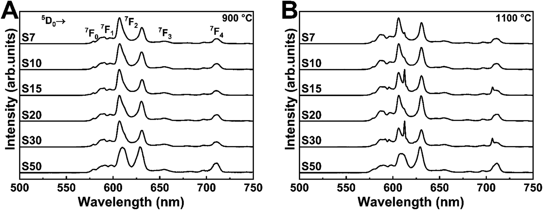
Fig. 1 shows the X-ray diffractograms of the Eu3+-doped samples annealed at 900 or 1100 °C. All crystalline planes correspond to the Y3TaO7 phase (JCPDS 01-071-1346 48-265), a fluorite-related orthorhombic structure with space group Ccmm30,38 and unit cell parameters a = 10.486, b = 7.426, and c = 7.448 Å. Six oxygen atoms surround tantalum, in an octahedral arrangement; yttrium atoms are coordinated with seven or eight oxygen atoms. The tantalum and yttrium atoms are organized as a deformed cube with missing oxygen and as a slightly deformed cube, respectively.30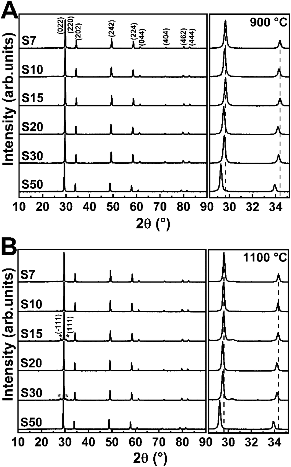 | ||
| Fig. 1 X-ray diffractograms of Eu3+-doped Y3TaO7 samples annealed at (A) 900 or (B) 1100 °C for 2 h. The M′-YTaO4 phase planes are marked (*). At the right side, a magnification in the region of 28–35° and 2θ shift is observed. | ||
Previously it was demonstrated that rising Eu3+ content up to 5.0 mol% leads to a secondary monoclinic crystalline phase named M′-YTaO4 (JCPDS 24-1425) with space group P12/a1, which is also verified for the non-doped host.32 The Eu3+ concentration of 7.0 mol% (sample S7) stabilizes Y3TaO7, and the secondary phase is absent. No significantly intense peaks related to Eu3+-based oxides or secondary crystalline phases appear even in the presence of higher Eu3+ concentration in the host, which indicates that Eu3+ ions are homogeneously distributed in the lattice, resulting in a solid solution, indicating that Y3TaO7 provides high RE ion solubility. The diffractogram of S15 and S30 annealed at 1100 °C display negligible low-intense diffraction peaks corresponding to the M′-YTaO4 phase, as observed by baseline magnification presented at the right side of Fig. 1. Therefore, this phase is considered as an impurity. The diffraction patterns observed for the samples afford only for the mentioned crystalline phases. No further peaks attributed to RE oxides were detected.
An expanded view of the diffractograms in the 2θ range of 28–35° can be observed in Fig. 1, where the most intense diffraction peaks appear for the Eu3+-doped Y3TaO7 samples annealed at 900 or 1100 °C. All the diffraction peaks shift to lower 2θ values at higher Eu3+ concentration. In agreement with Bragg's law, it indicates increasing interplanar spacing (d) in the Y3TaO7 crystalline structure. Higher interplanar spacing is due to the slightly larger Eu3+ ionic radius (1.066 Å) as compared to the ionic radius of the Y3+ ions (1.019 Å) that Eu3+ substitutes.39 Peak shifts toward lower angles confirm that a substitutional homogeneous solid solution (Y-Eu)3TaO7 emerges. The slight difference between the Eu3+ and Y3+ ionic radii culminates in mismatched sizes, so substitution of Y3+ for Eu3+ causes a slight lattice expansion.
We reported that Eu3+ incorporation into the Y3TaO7 host affects crystallization and delays formation of M′-YTaO4 as a secondary crystalline phase as compared to the undoped sample.32 M′-YTaO4 formation is pronounced up to a Eu3+ concentration of 5.0 mol% because Y3TaO7 decomposes and reacts with precipitated Ta2O5, to generate YTaO4.31 However, Eu3+ concentrations higher than 5.0 mol% induce Y3TaO7 phase stabilization because a solid solution arises. Y3TaO7 no longer decomposes, so YTaO4 is absent. The solid solution probably originates in a specific range of Eu3+ concentrations higher than 5.0 mol%.
As discussed before, Y3TaO7 contains two different Y3+ coordination sites in the unit cell: one-third of the Y3+ ions are octacoordinated, whereas two-thirds are heptacoordinated. Hinatsu et al.40 recently reported substitution in LnY2TaO7 for a series of lanthanides. When larger ions substitute Y3+, they preferentially occupy the octacoordinated position, whilst smaller ions tend to engage in heptacoordination. Therefore, unit cell parameters for Ln = Eu3+ are a = 10.5287, b = 7.4554, and c = 7.4926 Å;40 i.e., unit cell dimensions increase due to the presence of larger Eu3+ ions in the host.
Fig. 2A, B and Table 1 display the bandgap energy determined by using the absorption coefficients (estimated by the reflectance data and the Kubelka–Munk equation41 – Fig. S1 and S2, ESI†) and the Tauc plot42 for direct bandgap. Minor bandgap energy changes were detected, namely, from 4.76 to 4.86 eV for the samples annealed at 900 °C and from 4.71 to 4.85 eV for the samples annealed at 1100 °C. Only the samples S50 at both annealing temperatures showed lower values of band gap (4.54 and 4.66), which agrees with the observed in the XRD analysis. The literature reports a bandgap of 4.6 eV for Y3TaO7 (ref. 43) and a higher bandgap value for the resulting solid solution. We notice that the Eu3+ incorporation into the host lattice affects the bandgap energy. For samples S7–S50, their close band gap energy values show that a similar structure; i.e., stabilized (Y-Eu)3TaO7 solid solution. As already discussed for lower Eu3+ concentrations, these samples have high transparency in the UV range, and there is no luminescence quenching due to host absorption.
 | ||
| Fig. 2 Tauc plot of Eu3+-doped Y3TaO7 annealed at (A) 900 °C and (B) 1100 °C. | ||
| Sample | Host absorption (±0.01 eV) | |
|---|---|---|
| 900 °C | 1100 °C | |
| S7 | 4.79 | 4.85 |
| S10 | 4.86 | 4.83 |
| S15 | 4.76 | 4.84 |
| S20 | 4.83 | 4.83 |
| S30 | 4.78 | 4.71 |
| S50 | 4.54 | 4.66 |
The Eu3+-doped Y3TaO7 samples without annealing and annealed at 900 or 1100 °C were analyzed by FTIR (Fig. S3†). After annealing, the spectra indicate full removal of water and organic substances, which could decrease luminescence and quantum emission efficiency by the non-radiative process through excited-state deactivation. The higher frequency band is around 820 cm−1 (Ta–O–Ta stretching vibration44), highlighting that Y3TaO7 has relatively low phonon energy.
3.2 Luminescent properties
Fig. 3 depicts the excitation spectra of samples S7–S50 annealed at 900 or 1100 °C, monitored through the Eu3+ 7F0 → 5D2 transition at 607.0 nm. A broadband with more than one contribution in the UV region, centered at around 270 nm, emerges in all the spectra. It corresponds to charge transfer (CT) from an O2− (2p) partially filled shell to a Eu3+ (4f) filled shell and from the tantalate group, which is associated with the charge transfer between O2− to Ta5+.45,46 Moreover, the other contribution is associated with the host absorption. As observed previously, the energy gap values are approximately 4.8 eV (from 251 to 254 nm), which also corresponds to the range of the observed broadband and indicates the energy transfer from host lattice to Eu3+ excited states.47,48 Also, sharp peaks above 350 nm are characteristic of Eu3+ f–f transitions. The bands at 360, 394, 415, 462, and 529 nm are assigned to transitions from the ground state 7F0,1 to 5D4, 5L6, 5D3, 5D2, and 5D1, respectively. These spectral profiles are very similar to the spectral profiles of pure Y3TaO7 and of Y3TaO7 with lower Eu3+ concentrations (0.1 and 0.5 mol%).32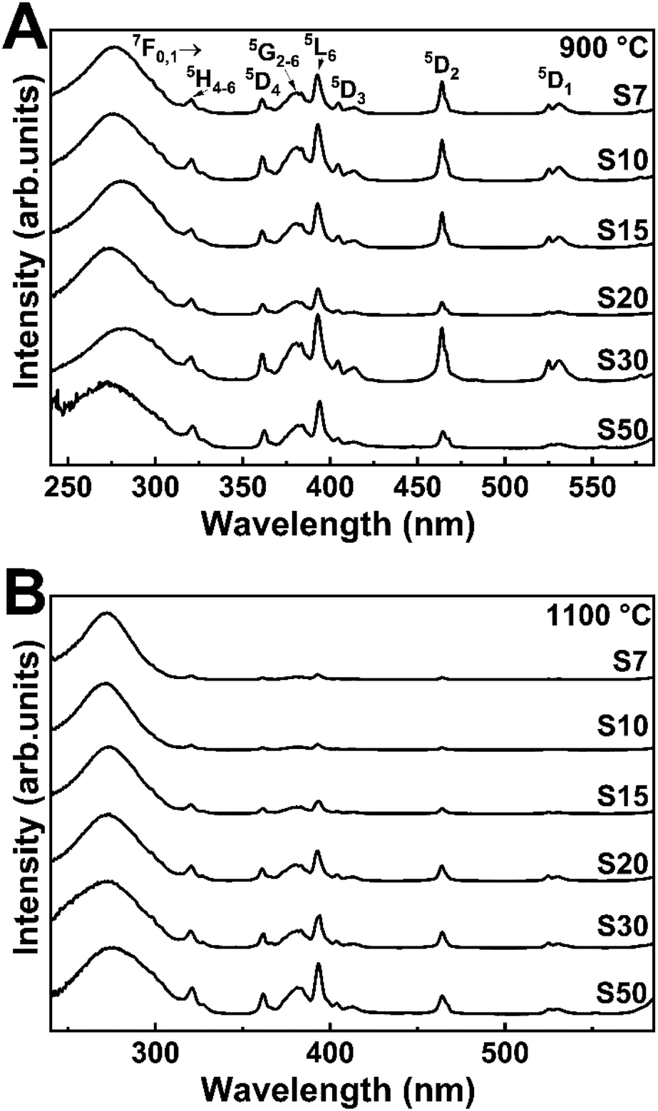 | ||
| Fig. 3 Excitation spectra at fixed emission wavelength of 607.0 nm of the Eu3+-doped Y3TaO7 samples annealed at (A) 900 and (B) 1100 °C. | ||
We recorded the emission spectra of Eu3+-doped Y3TaO7 samples annealed at 900 or 1100 °C (Fig. 4) under excitation at the CT band (∼275 nm). The emission spectra under excitation at the Eu3+ f–f transitions at 394 (7F0 → 5L6) and 464 nm (7F0 → 5D2) are depicted in Fig. S4.† These spectra contain mostly broad bands centered at 578, 590–595, 605–633, 653, and 710 nm, which refer to 5D0 → 7FJ (J = 0, 1, 2, 3, and 4), respectively.
 | ||
| Fig. 4 Emission spectra under excitation at CTB (∼275 nm) of Eu3+-doped Y3TaO7 samples annealed at (A) 900 or (B) 1100 °C. | ||
The samples annealed at 900 °C have emission spectra with very broadbands (full-width-at-half-maximum of, fwhm, ∼9 nm), independently of the selected excitation wavelengths, as already noticed.32 The Y3TaO7 crystalline structure contains two possible coordination sites for Y3+ ions; i.e., hepta- and octacoordination. Eu3+ probably replaces Y3+ in the two different symmetry sites and is randomly distributed. In these spectra, Eu3+ occupies the same average symmetry site. The broad (fwhm ∼ 70 cm−1) 5D0 → 7F0 transition detected in all the spectra suggests that Eu3+ occupies more than one symmetry site (without inversion center in accordance with the higher relative intensity of the 5D0 → 7F2 transition). The fact that the samples annealed at 900 °C display a similar spectral profile indicates high correspondence in terms of Eu3+ distribution in similar local-coordination symmetry sites. Eu3+-doped fluorite-related compounds with pyrochlore structure, such as rare-earth zirconates, hafnates, niobates, and tantalates, exhibit a similar spectral profile with analogous broad bands.11,22,23,49–51
The samples annealed at 1100 °C have slightly different spectra even in the presence of the same crystalline phase, as discussed previously. Concerning broadening, the samples annealed at 1100 °C clearly have the same pattern as the samples annealed at 900 °C. Depending on the excitation wavelength, a sharper peak at 611.5 nm stands out. When this sharper peak occurs more evidently, the 5D0 → 7F0 transition tends to disappear. This different emission profile resembles the Eu3+ emission profile in M′-RETaO4.32,52 In conclusion, most of the Eu3+ ions are occupying Y3TaO7 symmetry sites. However, as the temperature increases, and M′-YTaO4 is minimally formed, Eu3+ tends to occupy M′-YTaO4 symmetry; that is, Eu3+ substitutes Y3+ in a C2 site.47,53 Although this secondary phase is not evident in the XRD analysis, the photoluminescence spectra clearly indicate the formation of a distinct phase for the samples annealed at 1100 °C.
Table S1† shows the 5D0 → 7F2/5D0 → 7F1 intensity ratios, calculated from the respective area of each transition, fitted by Lorentzian functions, for all the Eu3+ doping concentrations and sample annealing temperatures. The samples annealed at 1100 °C have lower 5D0 → 7F2/5D0 → 7F1 ratios than the samples annealed at 900 °C mainly because fewer structural defects exist at higher annealing temperature, as discussed based on bandgap energy measurements. In general, Eu3+ occupies slightly higher symmetry sites in the samples annealed at 1100 °C. However, the difference between the samples is not significant, suggesting that Eu3+ is still in the same average symmetry sites.
Besides, it is also important to take the presence of Eu3+ in a different symmetry site into account for the samples S15 and S30 annealed at 1100 °C. The spectral profile of Eu3+ in Y3TaO7 symmetry sites can be seen for these samples in a magnified view and it will be discussed later. The more intense 5D0 → 7F2 transition band at 611.5 nm corresponds to Eu3+ occupying M′-YTaO4 sites.
In order to demonstrate the occupation of Eu3+ ions in two different symmetry sites of Y3TaO7 and M′-YTaO4 hosts, Fig. 5 shows the emission spectra for S15 at 1100 °C under different excitation wavelengths. Although the S15 sample annealed at 900 °C shows the crystallization of a single-phase, its emission spectrum was used as a reference to estimate the Eu3+ in Y3TaO7 emission of the sample annealed at 1100 °C. In Fig. 5 it is possible to observe the change in the S15 at 1100 °C sample spectral profile at different excitation wavelengths. The gray patterned area in each spectrum corresponds to the normalized spectrum of S15 at 900 °C, which has a pure Y3TaO7 phase and then multiplied by the indicated factor to adjust under the obtained spectra of S15 at 1100 °C. For this estimate, all spectra were normalized.
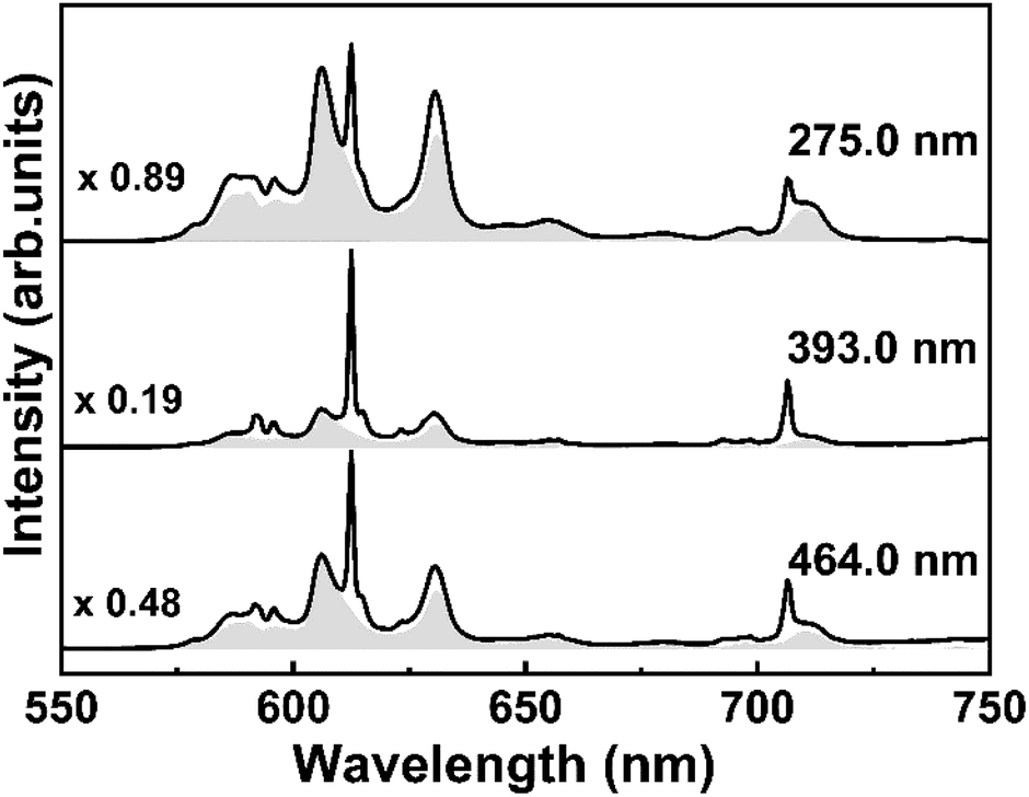 | ||
| Fig. 5 Emission spectra under different excitation wavelengths and submitted to a mathematic manipulation to show the contribution of the different symmetry sites present in the sample S15 annealed at 1100 °C. | ||
Under CT band excitation, at 275.0 nm, Eu3+ ions that are distributed into Y3TaO7 lattice are preferentially activated. The contribution of the band that corresponds to YTaO4 CT band is smaller at this excitation wavelength. Under excitation at 393.0 nm, the major contribution comes from the Eu3+ in M′-YTaO4 symmetry site, providing a sharper spectrum, even though the Eu3+ in Y3TaO7 is also present. Even for a small amount of the secondary phase, Eu3+ ions into M′-YTaO4 host is evident. For all these spectra in Fig. 5, both Eu3+ ions into Y3TaO7 and M′-YTaO4 were activated.
In Fig. 6, we tried to show the two different symmetry sites that appear in sample S15 annealed at 1100 °C separately. Fig. 6A shows the excitation spectra with fixed emission at two different wavelengths (607.0 and 611.5 nm), evidencing that the bands observed for 5D0 → 7F2 transition come from different symmetry sites. Eu3+ ions into Y3TaO7 lattice provides the large spectral profile and Eu3+ into M′-YTaO4 host, results in sharper spectra. In Fig. 6B, under 394.0 nm excitation, it is possible to activate almost only the Eu3+ into M′-YTaO4, with C2 symmetry.47 Under 392.5 nm excitation, Eu3+ ions in both hosts are activated. Even performing a time-resolved emission measurement under 392.5 nm excitation (Fig. S5†), it was not possible to distinguish different symmetry site besides the diminish of the peak referent to Eu3+ into M′-YTaO4, at 611.5 nm, which possess lower lifetime than Eu3+ ions into Y3TaO7.
 | ||
| Fig. 6 (A) Excitation spectra with emission fixed at 607.0 and 611.5 nm. (B) Emission spectra upon excitation at 392.5 and 394.0 nm. | ||
Fig. 7 contains the 5D0 excited state emission decay curves for all the Eu3+-doped Y3TaO7 samples annealed at 900 or 1100 °C under excitation at CT band with emission at 607 nm (the curves under excitation at 393 and 464 nm are presented in Fig. S6, ESI†). The samples display an almost single exponential behavior and have been fitted by using a first-order exponential. This indicates that even Eu3+ ions exist in different symmetry sites, the lifetime values are close to each other. We obtained τ1 lifetimes values from decay curves for each sample under different excitation wavelengths (see Table 3).
 | ||
| Fig. 7 PL decay curves for curves for the Eu3+ 5D0 excited state under excitation at CTB of Eu3+ doped Y3TaO7 samples annealed at (A) 900 or (B) 1100 °C with fixed emission at 607.0 nm. Inset: lifetime values (τobs) as a function of Eu3+ concentration (from 0.1 [30] up to 50 mol%) under excitation at CTB. The lines are visual guides. | ||
Samples with higher Eu3+ concentration (S7–S50) behave in the same way as samples doped with lower Eu3+ concentration (0.1 up to 5.0 mol%). The samples annealed at 1100 °C have higher τ1/e values, which refer to greater elimination of species (like OH groups) that deactivate the Eu3+ excite state. We already observed that Eu3+-doped Y3TaO7 has a long lifetime (about 1.80 ms for the sample containing Eu3+ at 0.5 mol%, annealed at 1100 °C).32 The lifetime of samples with higher Eu3+ concentration (S7–S50) that have stabilized Y3TaO7 crystalline phase is longer than that of the samples with lower concentration (up to 5 mol%).
Analysis of these samples under the same excitation wavelength and with Eu3+ concentration higher than 20 mol% shows that these samples have reduced τ1/e. Although the S30 and S50 samples exhibit strong luminescence, the lifetime values suggest quenching by concentration: a shorter Eu3+ ion – Eu3+ ion distance promotes energy transfer. Energy migration combined with host defects explains such quenching.
For the samples annealed at 1100 °C that exhibited the sharp peak at 611.5 nm (Fig. 4B, S4B and D†), we measured the lifetime of both peaks that are assigned to 5D0 → 7F2 transition, the large one at λem = 607.0 nm (as can be seen in Fig. 7 and Table 2) and the sharp one at λem = 611.5 nm. The decay curves of these samples for this last-mentioned wavelength were adjusted with the non-single exponential fit, that was not reported here, and the τ1/e values are exhibited in Table 3. Lower τ1/e values were obtained under excitation at 393.0 and 464.0 nm with emission fixed at 611.5 nm than the values obtained with the emission at 607.0 nm.
| Annealing temperature (°C) | Sample | CTB | 393.0 nm | 464.0 nm |
|---|---|---|---|---|
| 900 | S7 | 1.74 | 1.68 | 1.59 |
| S10 | 1.75 | 1.73 | 1.66 | |
| S15 | 1.68 | 1.48 | 1.52 | |
| S20 | 1.54 | 1.53 | 1.52 | |
| S30 | 1.00 | 1.01 | 1.00 | |
| S50 | 0.13 | 0.12 | 0.12 | |
| 1100 | S7 | 2.18 | 2.14 | 2.00 |
| S10 | 2.16 | 2.10 | 2.02 | |
| S15 | 2.08 | 1.96 | 1.96 | |
| S20 | 1.87 | 1.81 | 1.81 | |
| S30 | 0.86 | 0.96 | 0.90 | |
| S50 | 0.17 | 0.18 | 0.19 |
| Samples | τ1/e (±0.01 ms) | |
|---|---|---|
| 393.0 nm | 464.0 nm | |
| S7 | 1.42 | 1.41 |
| S10 | 1.41 | 1.48 |
| S15 | 1.26 | 1.31 |
| S20 | — | 1.41 |
| S30 | 0.70 | 0.80 |
The shorter lifetime values may be related to increasing Eu3+ content to structural changes (Y3TaO7 → M′-YTaO4) because Eu3+ in the latter phase has a shorter lifetime.32 Eu3+ ions that occupy symmetry sites in this structure have a shorter lifetime and lower symmetry (C2). Photoluminescent measurements and lifetime decay curves of most of the samples annealed at 1100 °C have shown the presence of the M′-YTaO4 crystalline phase, which had not been detected in the XRD diffractograms. The lifetime values of the samples showed in Table 3 are similar to those values of samples doped with 1, 2, and 5 mol% of Eu3+ concentration.32
In order to observe the quenching effect as a function of Eu3+ concentration, Fig. S7† brings τ1/e values for each sample, measured with emission fixed at 607.0 nm for the 5D0 → 7F2 transition, for evaluation in the Y3TaO7 host. Samples S10 and S7 have a longer lifetime, for samples annealed at 900 °C and 1100 °C, respectively. Although lifetime decreases slightly from S7 to S20, their τ1/e values are close. Samples S30 and S50 have significantly lower lifetime values, indicating that quenching due to concentration takes place. The lifetime dependence on the excitation wavelength is another argument supporting distinct local-coordination sites. Also, the presence of CTB intermediate state in near-resonance with the 5D0 emitting level mediating energy transfer is known to induce a lifetime increases relative to its intrinsic or natural lifetime measured under direct intra-4f6 excitation (393.0 and 464.0 nm).54
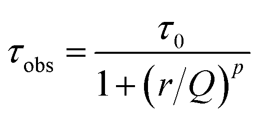
It is possible to describe the behavior of the 5D0 excited state lifetime values decreases as a function of Eu3+ ions concentration from the following equation:55,56
 | (1) |
![[thin space (1/6-em)]](https://www.rsc.org/images/entities/char_2009.gif) 32 were included in this calculus since the Eu3+ are in the same symmetry sites of the samples presented in this work.
32 were included in this calculus since the Eu3+ are in the same symmetry sites of the samples presented in this work.
The best fit obtained from the equation data for each curve is represented by a red line. Therefore, the average calculated parameters were: τ0 = 1.62 ± 0.01 ms, Q = 32 mol%, and p = 5 for the samples annealed at 900 °C and τ0 = 2.01 ± 0.01 ms, Q = 29 mol%, and p = 5 for the samples annealed at 1100 °C. These yttrium tantalate samples had exhibited a high quenching concentration at about 30 mol% of Eu3+ ions, a much higher value than the observed for other materials, such zirconates, hafnates,22,23 antimonates,9 for example. The high quenching concentration of Eu3+ ions in this host can be attributed to the facility of substitution of these ions in the place of Y3+ ions of the host, therefore, the RE3+ ions have high solubility in this host due to the similarity of ionic radii.
Judd–Ofelt intensity parameters, radiative (Arad) and nonradiative (Anrad) transition probabilities were calculated based on emission spectra under excitation at 393 nm shown at Fig. S4.† The refractive index used to calculate these parameters was 1.8, estimated by using specular reflectance on a film prepared using the same precursors as the powders, by dip-coating technique.32 The calculated values were based on the characteristic spectra of Y3TaO7 as well as the comparison with the experimental lifetime values, where the emission was fixed at the Y3TaO7 5D0 → 7F2 transition (∼607 nm). The quantum efficiency values were omitted due the very close values between the τexp and τrad calculated. Therefore, the calculated quantum efficiency for some samples showed values higher than 100%. This can be an indicative that the refractive index value used for the calculations do not corresponds to the real value of the samples, affecting the obtained value. The powder annealing can result in a material with less densification, smaller refractive index value and, thus, a higher lifetime value. This behavior can be observed in nanostructured materials. For example, in Y2O3:Eu3+ samples where the radiative lifetime is 0.9 ms (calculated and measured from a monocrystal), for particulated nanostructured materials, the experimental lifetime value is highly dependent on the annealing temperature. Previous studies showed that lifetime values higher than 0.9 ms, and as the material was annealed at higher temperatures or for longer time, there was a reduction in these lifetime values.57,58 This fact can explain the higher τexp found for these yttrium tantalate samples.
Even though, this group of samples has presented higher values of radiative transition probabilities (Arad) and τrad than the group of samples with lower Eu3+ concentration.32 In the previous work, it was shown that these samples clearly show the presence of M′-YTaO4 phase. To show the influence of Eu3+ ions located in this phase on Arad and τrad, it was calculated these values based on the almost isolated emission spectra of sample S15 annealed at 1100 °C depicted in Fig. 6B (λex = 394 nm) and the τexp presented in Table 4 (λem = 611.5 nm). The quantum efficiency value calculated for this sample was 57%.
| Annealing temperatures | Samples | Ω2 (10−20 cm2) | Ω4 (10−20 cm2) | Arad (s−1) | τrad (ms) | τexp (ms) |
|---|---|---|---|---|---|---|
| a This values are referent to the emission spectra of Fig. 6B, which represents the Eu3+ ions into the M′-YTaO4 sites almost isolated, in contrast to values calculated for Eu3+ ions into Y3TaO7 lattice. | ||||||
| 900 °C | S7 | 7.34 | 4.03 | 592 | 1.69 | 1.63 |
| S10 | 7.63 | 3.97 | 606 | 1.65 | 1.76 | |
| S15 | 7.23 | 3.33 | 569 | 1.76 | 1.43 | |
| S20 | 7.24 | 3.97 | 584 | 1.71 | 1.51 | |
| S30 | 7.40 | 3.51 | 583 | 1.72 | 0.99 | |
| S50 | 9.29 | 4.19 | 697 | 1.43 | 0.13 | |
| 1100 °C | S7 | 5.78 | 2.26 | 462 | 2.16 | 2.14 |
| S10 | 6.08 | 2.40 | 481 | 2.08 | 2.09 | |
| S15 | 6.57 | 5.38 | 587 | 1.70 | 1.93 | |
| S15a | 5.61 | 2.01 | 451 | 2.22 | 1.26 | |
| S20 | 5.32 | 2.13 | 431 | 2.32 | 1.78 | |
| S30 | 6.69 | 6.42 | 620 | 1.61 | 0.98 | |
| S50 | 7.02 | 3.27 | 550 | 1.82 | 0.19 | |
Table 4 lists the experimental Ω2 and Ω4 intensity parameter values for all the samples and the refractive index value used was 1.8. The values of sample S15 at 1100 °C marked (a) are referent of the same emission spectra referred previously (Fig. 6B).
The samples with higher Eu3+ concentration have presented higher Ω2 than the samples with lower concentration.32 The environment could become more polarizable and less symmetric, which agrees with the 5D0 → 7F2/5D0 → 7F1 asymmetric ratio (Table S1†).
Absolute emission quantum yield was measured and the obtained values are shown in Table 5. Under excitation at CTB (250 and 280 nm), the values were about 10%. For other fluorite-type structure materials, the obtained values were 15–18% for Y2Hf2O7:5% Eu3+,50 9.89% for La2Hf2O7:5% Eu3+,22 and 17.6% for La2Zr2O7:5% Eu3+23 under 258 nm (CTB) excitation. These values were comparable to the values obtained for the Eu3+-doped Y3TaO7 when excited at the same wavelength. For the excitation at 393 and 464 nm (direct excitation at Eu3+ ion levels 5L6 and 5D2, respectively), the obtained values were higher, reaching approximately 30% for the S10 sample annealed at 1100°C, superior than other materials described in literature, such as YAG:16% Eu3+, which shows a quantum yield value of 15.5%.59
| λ (nm) | 900 °C | 1100 °C | |||||
|---|---|---|---|---|---|---|---|
| S7 | S10 | S20 | S50 | S10 | S20 | S50 | |
| 250 | 7.4 | 10.0 | 11.0 | — | 8.8 | 11.0 | 3.9 |
| 280 | 7.1 | 9.9 | 9.3 | — | 7.2 | 10.0 | 1.7 |
| 320 | 2.9 | 4.7 | 5.3 | — | 1.9 | 5.7 | 1.3 |
| 393 | — | 17.0 | 11.0 | 2.5 | 6.0 | 14.0 | 10.0 |
| 464 | — | 29.0 | 15.0 | 2.6 | 16.0 | 15.0 | 7.0 |
Fig. 8 shows the Commission Internationale d'Eclairage (CIE) 1931 chromaticity diagram and the values calculated for the (x, y) color coordinates from the emission spectra of the samples under excitation at CTB. The emission color of all Eu3+-doped Y3TaO7 samples is reddish-orange.
 | ||
| Fig. 8 CIE 1931 chromaticity diagram of Eu3+-doped Y3TaO7 samples annealed at (A) 900 or (B) 1100 °C under excitation at CTB. | ||
The orange emission is the strongest in Eu3+-doped rare-earth titanates.60 Eu3+ is located at a centrosymmetric site in compounds with the pyrochlore structure (D3d), so electric dipole transitions are forbidden. The 5D0 → 7F1 magnetic dipole transition is the strongest emission in this case, and distortions to the symmetry site can be evaluated by splitting of this transition.19 The emission of the 5D0 → 7F1 transition is orange. For zirconates and hafnates, their structures are distorted in such a way that the electric dipole transitions become stronger. In these structures, the orange emission is stronger when Eu3+ is located in sites with an inversion center because the 5D0 → 7F1 transition dominates. In distorted lattices, the local symmetry becomes distorted (deviation from the inversion center), and the red emission component dominates.61
The symmetry sites are greatly distorted in Y3NbO7 (ref. 49 and 62) and Y3TaO7. Consequently, these compounds present the 5D0 → 7F0 transition and high-relative intensity 5D0 → 7F2 transition, so emission is redder. In Eu3+-doped Y3SbO7,9 which belongs to the same space group as Y3TaO7, emission goes from reddish-orange to red with increasing Eu3+ concentration. It is possible to see that the emission of Eu3+ inserted in Y3TaO7 host is reddish-orange almost independently of the increasing of Eu3+ concentration in this case.
The emission becomes redder depending on the amount of M′-YTaO4 in the structure.32 The higher the Eu3+ concentration, the more stable the Y3TaO7 solid solution, so emission color tends to orange. This indicates that the emission of the compounds is tunable, depends on the structure, and can be tailored by the Eu3+ concentration in the host.
The purity of the emitted color can be characterized from the equation below:63,64
 | (2) |
4. Conclusions
We successfully synthesized Y3TaO7 solid solutions containing high Eu3+ concentration, from 7 up to 50 mol%. It was evaluated the Y3TaO7 structural features after Eu3+ introduction into the lattice and also evaluated the photoluminescence properties; Eu3+ ions photoluminescence properties functioned as a structural probe. The higher the Eu3+ concentration, the more stable the Y3TaO7 crystallization. Emission bands were intense (q ∼ 30%) and broad (fwhm ∼ 9 nm). Inhomogeneous broadening was due to the occupation of Eu3+ ions in a different symmetry sites. Eu3+ emission quenching due to concentration was negligible for the samples containing up to 30 mol%, and quantum yield values of nearly 30% were obtained with excitation in Eu3+ f–f transitions, which makes these materials especially interesting for application as high-intensity emitters in photonics. The results reported here call attention to the design of materials based on the tunability of their emission color through manipulation of their crystalline structure, which can be tailored by controlling the Eu3+ quantity in the sample.Conflicts of interest
There are no conflicts to declare.Acknowledgements
The authors want to acknowledge Brazilian Funding Agencies FAPESP (grant number 2017/11301-2 and the scholarships processes numbers 2017/10424-3 and 2018/04587-0), CNPq and CAPES for financial support. This work was also developed within the scope of the project CICECO-Aveiro Institute of Materials, UIDB/50011/2020 & UIDP/50011/2020, financed by national funds through the FCT/MEC and when appropriate co-financed by FEDER under the PT2020 Partnership Agreement. We also would like to thank Mrs Cynthia Maria de Campos Prado Manso for reviewing the text.References
- C. N. R. Rao, Annu. Rev. Phys. Chem., 1989, 40, 291–326 CrossRef CAS.
- Y. Kanke and A. Navrotsky, J. Solid State Chem., 1998, 141, 424–436 CrossRef CAS.
- E. De la Rosa-Cruz, L. A. Diaz-Torres, P. Salas and R. A. Rodriguez, in Third International Conference on Solid State Lighting, SPIE, 2004, vol. 5187, p. 150 Search PubMed.
- D. Michel, M. P. y. Jorba and R. Collongues, J. Raman Spectrosc., 1976, 5, 163–180 CrossRef CAS.
- S. V. Krivovichev, Solid State Sci., 1999, 1, 211–219 CrossRef CAS.
- J. L. Payne, M. G. Tucker and I. R. Evans, J. Solid State Chem., 2013, 205, 29–34 CrossRef CAS.
- Y. Doi, Y. Harada and Y. Hinatsu, J. Solid State Chem., 2009, 182, 709–715 CrossRef CAS.
- Y. Hinatsu, H. Ebisawa and Y. Doi, J. Solid State Chem., 2009, 182, 1694–1699 CrossRef CAS.
- J. Wang, Y. Cheng, Y. Huang, P. Cai, S. Il Kim and H. J. Seo, J. Mater. Chem. C, 2014, 2, 5559–5569 RSC.
- K. P. F. Siqueira, R. M. Borges, E. Granado, L. M. Malard, A. M. De Paula, R. L. Moreira, E. M. Bittar and A. Dias, J. Solid State Chem., 2013, 203, 326–332 CrossRef CAS.
- T. Linda Francis, P. Prabhakar Rao, S. K. Mahesh, T. S. Sreena and S. Parvathi Babu, Opt. Mater., 2016, 52, 134–143 CrossRef CAS.
- H. J. Rossell, J. Solid State Chem., 1979, 27, 115–122 CrossRef CAS.
- H. J. Rossell, J. Solid State Chem., 1979, 27, 287–292 CrossRef CAS.
- Y. Hinatsu and Y. Doi, J. Ceram. Soc. Jpn., 2019, 127, 273–278 CrossRef CAS.
- A. Egaña, E. Cantelar, M. Tardío and J. E. Muñoz Santiuste, Opt. Mater., 2019, 97, 109393 CrossRef.
- L. T. Francis, P. Prabhakar Rao, M. Thomas, S. K. Mahesh, V. R. Reshmi and T. S. Sreena, Phys. Chem. Chem. Phys., 2014, 16, 17108–17115 RSC.
- L. Cai and J. C. Nino, Acta Crystallogr., Sect. B: Struct. Sci., 2009, 65, 269–290 CrossRef CAS PubMed.
- K. E. Sickafus, R. W. Grimes, J. A. Valdez, A. Cleave, M. Tang, M. Ishimaru, S. M. Corish, C. R. Stanek and B. P. Uberuaga, Nat. Mater., 2007, 6, 217–223 CrossRef CAS.
- R. A. McCauley and F. A. Hummel, J. Lumin., 1973, 6, 105–115 CrossRef CAS.
- C. R. Stanek, C. Jiang, B. P. Uberuaga, K. E. Sickafus, A. R. Cleave and R. W. Grimes, Phys. Rev. B: Condens. Matter Mater. Phys., 2009, 80, 17 CrossRef.
- M. A. Subramanian, G. Aravamudan and G. V. Subba Rao, Prog. Solid State Chem., 1983, 15, 55–143 CrossRef CAS.
- K. Wahid, M. Pokhrel and Y. Mao, J. Solid State Chem., 2017, 245, 89–97 CrossRef CAS.
- M. Pokhrel, M. Alcoutlabi and Y. Mao, J. Alloys Compd., 2017, 693, 719–729 CrossRef CAS.
- K. P. F. Siqueira, J. C. Soares, E. Granado, E. M. Bittar, A. M. De Paula, R. L. Moreira and A. Dias, J. Solid State Chem., 2014, 209, 63–68 CrossRef CAS.
- Y. Hinatsu and Y. Doi, J. Solid State Chem., 2013, 198, 176–185 CrossRef CAS.
- M. Wakeshima and Y. Hinatsu, J. Solid State Chem., 2010, 183, 2681–2688 CrossRef CAS.
- D. Harada and Y. Hinatsu, J. Solid State Chem., 2001, 158, 245–253 CrossRef CAS.
- M. Wakeshima, H. Nishimine and Y. Hinatsu, J. Phys.: Condens. Matter, 2004, 16, 4103–4120 CrossRef CAS.
- S. Fujihara and K. Tokumo, Chem. Mater., 2005, 17, 5587–5593 CrossRef CAS.
- W. T. Fu and D. J. W. IJdo, J. Solid State Chem., 2009, 182, 2451–2455 CrossRef CAS.
- V. V. Molchanov, M. G. Zuev, L. M. Plyasova and S. V. Bogdanov, Inorg. Mater., 2004, 40, 73–79 CrossRef CAS.
- F. H. Borges, F. J. Caixeta, R. R. Pereira, S. R. de Oliveira and R. R. Gonçalves, J. Lumin., 2018, 199, 143–153 CrossRef CAS.
- D. Chen and Y. Wang, Nanoscale, 2013, 5, 4621–4637 RSC.
- E. Setiawati and K. Kawano, J. Alloys Compd., 2008, 451, 293–296 CrossRef CAS.
- D. A. Rani, Y. Yoshizawa, K. Hirao and Y. Yamauchi, J. Am. Ceram. Soc., 2004, 87, 289–292 CrossRef CAS.
- K. P. F. Siqueira and A. Dias, Mater. Res., 2014, 17, 167–173 CrossRef CAS.
- Y. Yokogawa and M. Yoshimura, J. Am. Ceram. Soc., 1991, 74, 2077–2081 CrossRef CAS.
- Y. Yokogawa, M. Yoshimura and S. Somiya, Mater. Res. Bull., 1987, 22, 1449–1456 CrossRef CAS.
- R. D. Shannon, Acta Crystallogr., Sect. A: Cryst. Phys., Diffr., Theor. Gen. Crystallogr., 1976, 32, 751–767 CrossRef.
- Y. Hinatsu and Y. Doi, J. Solid State Chem., 2016, 233, 37–43 CrossRef CAS.
- E. M. Patterson, C. E. Shelden and B. H. Stockton, Appl. Opt., 1977, 16, 729 CrossRef CAS PubMed.
- J. Tauc, R. Grigorovici and A. Vancu, Phys. Status Solidi, 1966, 15, 627–637 CrossRef CAS.
- R. Abe, M. Higashi, K. Sayama, Y. Abe and H. Sugihara, J. Phys. Chem. B, 2006, 7, 2219–2226 CrossRef PubMed.
- G. Blasse and G. P. M. Van Den Heuvel, Phys. Status Solidi, 1973, 19, 111–117 CrossRef CAS.
- K. P. F. Siqueira, P. P. Lima, R. A. S. Ferreira, L. D. Carlos, E. M. Bittar, F. M. Matinaga, R. Paniago, K. Krambrock, R. L. Moreira and A. Dias, J. Phys. Chem. C, 2015, 119, 17825–17835 CrossRef CAS.
- M. Zhao, Z. Zhao, L. Yang, X. Wang, F. Yan and C. Xing, J. Mater. Sci.: Mater. Electron., 2017, 28, 16008–16012 CrossRef CAS.
- B. Li, Z. Gu, Y. Dong, J. Lin and M. Su, Chem. Res. Chin. Univ., 1999, 15, 226–231 CAS.
- G. Blasse and A. Bril, J. Lumin., 1970, 3, 109–131 CrossRef CAS.
- K.-Y. Kim, U.-C. Chung, B. Mutulet, F. Weill, A. Demourgues, J. Rossit, J.-M. Heintz, A. Veillere and V. Jubera, Inorg. Chem., 2017, 56, 4495–4503 CrossRef CAS PubMed.
- M. Pokhrel, K. Wahid and Y. Mao, J. Phys. Chem. C, 2016, 120, 14828–14839 CrossRef CAS.
- J. Papan, D. J. Jovanović, K. Vuković, K. Smits, V. Đorđević and M. Dramićanin, Opt. Mater., 2016, 61, 68–76 CrossRef CAS.
- B. Li, Z. Gu, J. Lin and M. Z. Su, J. Mater. Sci., 2000, 35, 1139–1143 CrossRef CAS.
- B. Li, Z. Gu, J. Lin and M. Z. Su, Mater. Res. Bull., 2000, 35, 1921–1931 CrossRef CAS.
- R. A. S. Ferreira, M. Nolasco, A. C. Roma, R. L. Longo, O. L. Malta and L. D. Carlos, Chem.–Eur. J., 2012, 18, 12130–12139 CrossRef CAS PubMed.
- X. Orignac, D. Barbier, X. Min Du, R. M. Almeida, O. McCarthy and E. Yeatman, Opt. Mater., 1999, 12, 1–18 CrossRef CAS.
- R. R. Gonçalves, G. Carturan, M. Montagna, M. Ferrari, L. Zampedri, S. Pelli, G. C. Righini, S. J. L. Ribeiro and Y. Messaddeq, in Optical Materials, Elsevier, 2004, vol. 25, pp. 131–139 Search PubMed.
- K. De Oliveira Lima, R. Rocha Gonçalves, D. Giaume, A. Ferrier and P. Goldner, J. Lumin., 2015, 168, 276–282 CrossRef CAS.
- J. L. Ferrari, M. A. Schiavon, R. R. Gonçalves, A. M. Pires and M. R. Davolos, Thin Solid Films, 2012, 524, 299–303 CrossRef CAS.
- I. E. Kolesnikov, D. V. Tolstikova, A. V. Kurochkin, A. A. Manshina and M. D. Mikhailov, Opt. Mater., 2014, 37, 306–310 CrossRef CAS.
- A. Garbout, N. Kallel Kchaou and M. Férid, J. Lumin., 2016, 169, 359–366 CrossRef CAS.
- M. Hirayama, N. Sonoyama, A. Yamada and R. Kanno, J. Lumin., 2008, 128, 1819–1825 CrossRef CAS.
- K. Y. Kim, A. Durand, J. M. Heintz, A. Veillere and V. Jubera, J. Solid State Chem., 2016, 235, 169–174 CrossRef CAS.
- Y.-F. Wu, Y.-T. Nien, Y.-J. Wang and I.-G. Chen, J. Am. Ceram. Soc., 2012, 95, 1360–1366 CrossRef CAS.
- T. S. Sreena, P. P. Rao, A. K. V. Raj and T. R. A. Thara, J. Alloys Compd., 2018, 751, 148–158 CrossRef CAS.
- V. Dubey, J. Kaur, S. Agrawal, N. S. Suryanarayana and K. V. R. Murthy, Superlattices Microstruct., 2014, 67, 156–171 CrossRef CAS.
- Y. Ren, Y. Liu and R. Yang, Superlattices Microstruct., 2016, 91, 138–147 CrossRef CAS.
- Y. Han, F. Song, Q. Li, F. Wang, C. Ming and J. Tian, Opt. Mater., 2014, 37, 756–759 CrossRef CAS.
Footnote |
| † Electronic supplementary information (ESI) available. See DOI: 10.1039/d0ra01912g |
| This journal is © The Royal Society of Chemistry 2020 |