 Open Access Article
Creative Commons Attribution 3.0 Unported Licence
Facile fabrication, characterization and catalytic activity of a NiMo/Al2O3 nanocatalyst via a solution combustion method used in a low temperature hydrodesulfurization process: the effect of fuel to oxidant ratio†
Roya Hamidia,
Reza Khoshbin b and
Ramin Karimzadeh*a
aChemical Engineering Faculty, Tarbiat Modares University, P. O. Box 14115-114, Tehran, Islamic Republic of Iran. E-mail: ramin@modares.ac.ir; Fax: +98-21-88006544; Tel: +98-21-82883315
bDepartment of Chemical and Materials Engineering, Buein Zahra Technical University, Buein Zahra, Qazvin, Iran
First published on 26th March 2020
Abstract
Novel bimetallic NiMo/Al2O3 nanocatalysts were fabricated via a solution combustion method to evaluate the role of fuel to oxidant molar ratios on their structural properties and hydrodesulfurization activity. The citric acid/oxidant ratios of 0.5, 1, 2 and 4 were selected to address the optimum ratio. Characterization results demonstrated that the content of citric acid considerably influenced the morphological and textural properties of the nanocatalysts. Such morphology modification is attributed to the consequent difference of the effluent exhaust gas during combustion. We show that with our method a relatively homogeneous distribution of the active material over the support can be achieved. The obtained data from N2 adsorption–desorption analysis illustrated that at a fuel/oxidant ratio of 4 the external and surface area were ca. 2.1 and 1.5 times more than the corresponding one in the fuel/oxidant ratio of 0.5, respectively. Furthermore, a higher amount of fuel can improve the catalyst reducibility by decreasing the interaction of metal active phase with the support surface. The catalytic performance of sulfided nanocatalysts is evaluated in a slurry reactor, operated at ambient pressure using high thiophene contamination as a model fuel. The solution combustion synthesis method was able to remove 100% of the sulfur compound in the reaction medium.
1 Introduction
Refined petroleum products such as gasoline and diesel fuels usually contain a significant amount of sulfur compounds which produce SOx gases. These gases reduce the efficiency of the petrochemical units and cause corrosion to the refinery equipment.1,2 Also, such emission may cause health problems when inhaled, and in the environment, it forms acid rain which can have negative effects on ecosystems. Because of these unpleasant consequences, environmental regulation has been increased aiming at intense reduction of the sulfur content level to 10 μg g−1.3,4 Among all the physiochemical methods employed for desulfurization, such as adsorptive desulfurization, hydrodesulfurization, supercritical water desulfurization and oxidative desulfurization, the hydrodesulfurization (HDS) process has received more attention for removing organic sulfur. This catalytic reaction is generally carried out at high temperature and hydrogen partial pressure.5,6Generally, hydrotreating reactions are catalyzed by molybdenum/tungsten disulfide and promoted with cobalt/nickel, which is placed at the edge of MoS2/WS2 slabs.10–12 Numerous substances have been applied as support in the HDS process, including gamma-alumina, zeolites, metal oxides, carbon-based material, silica and their composite.13–16 Among of them, gamma-alumina has considered the most commonly used because of low cost, moderate acidsites, considerable mechanical properties and adequate porosity.17,18
In order to obtain superior hydrodesulfurization performance, modified catalyst should be utilized, which could be achieved by the employment of novel preparation methods or incorporation of suitable promotors. Positive effects of various promotors such as zirconia,18 titania,19 fluorine,20 boron21 and phosphorus22 have been reported by numerous studies. It is also well established that the addition of chelating ligands in the catalyst preparation is a beneficial way to improve catalytic performance in the HDS process.23 In the presence of chelating agents, molybdate and tungstate anions are not strongly bonded to the support. This issue makes them easily sulfided to MoS2 and WS2 crystallites which are the catalytically active sites.24
In literature, impregnation method attracted widespread attention for the preparation of HDS catalysts. However, several methods such as precipitation, sol–gel, chemical vapor deposition, sonochemical and hydrothermal deposition have been applied in the last decades.16,20,25–29 Although the above-mentioned preparation methods have had the opportunity to produce advanced hydrodesulfurization catalysts, they suffer from some drawbacks. Some of these disadvantages are relatively complicated equipment, prolonged synthesis time, multistage process, high-energy consumption, poor control of physicochemical properties, need subsequent milling process, expensive starting substance and environmental concerns. These drawbacks make them unsuitable for large scale production.30,31 Consequently, an alternative method, called urea matrix combustion, was explored by González-Cortés et al.32–34 to overcome the aforementioned drawbacks. Their results demonstrated that the generation of mono and polymolybdate with superior reducibility have been facilitated by the urea–organic matrix compared with the impregnation and chelating methods, and accordingly increase the catalyst performance.
This method is an effective time and energy-saving technique for the synthesis of various inorganic powders with high purity and excellent characteristics which is based on a redox reaction between an organic fuel and oxidant.21 Solution combustion synthesis (SCS) involves a self-sustained exothermic reaction in a homogeneous mixture of different oxidants, including nitrate, sulfates and carbonates, and fuels such as citric acid, urea, glycine, sucrose, ethylene glycol. The initial solution self-ignites by preheating it to a moderate temperature which leads to the formation of fine solid powders.35 The as-combusted material has a porous structure which is designed by the liberation of gaseous by-products like CO2, H2O, N2, CO during the process.36 Initial heating in the solution combustion reaction can be applied using a normal oven or irradiating waves such as microwaves.37 Manikandan et al.38 reported Fe3O4 powders prepared by microwave heating had higher surface area and smaller crystallite size compared to conventional heating. Also, the combustion reaction rate depended on pH values as investigated by Radpour et al.39 Fuel to oxidant ratio is another parameter due to its important role in the combustion method. In this sense, Zhang et al.40 studied the role of fuel content on the porous structure of as-combusted Fe3O4 powders. Briefly, fuel type, fuel to oxidant ratio, heating method and pH value of prepared gel must be carefully adjusted to obtain optimum results in the SCS method.
It is important to say that although the application of the combustion technique has been broadly used for the preparation of various materials for different applications, just limited studies investigated this kind of treatment on the synthesis of HDS catalysts. The aim of the current work was centralized on study the influence of fuel/oxidant molar ratio on the properties of NiMo/γ-A12O3 HDS catalysts utilizing citric acid to oxidant molar ratio of 0.5, 1, 2, 4. X-ray diffraction (XRD), thermogravimetric analysis (TGA), field emission scanning electron microscopy (FESEM), energy dispersive X-ray spectrometry (EDX), transmission electron microscopy (TEM), N2 adsorption–desorption and temperature-programmed reduction (H2-TPR) techniques were conducted to characterize the properties of as-combusted NiMo/Al2O3 catalysts. The performance of prepared samples has been investigated in HDS reactions using 3.5 wt% thiophene in n-decane as model feed operated at atmospheric pressure. Ultimately, the evaluation of thiophene concentration in the treated product was conducted by GC analysis.
2 Materials and methods
2.1 Materials
Starting substances which used for the synthesis of NiMo supported catalyst were γ-alumina (as support), provided from Ardakan Industrial Ceramic Co. (Yazd, Iran), (NH4)6Mo7O24·4H2O (as molybdenum source) and Ni(NO3)2·6H2O (as nickel source) supplied by Merck company. Citric acid (Ghatran shimi) and ammonia (Merck) were used for the combustion synthesis method. Also, to assess the HDS performance of catalysts, C10H22 (Merck) and C4H4S (Merck) were utilized as solvent and model sulfur compound, respectively. Furthermore, CS2 (Merck) and C7H16 (Merck) were used for sulfiding of NiMo supported catalysts.2.2 Nanocatalyst preparation and procedures
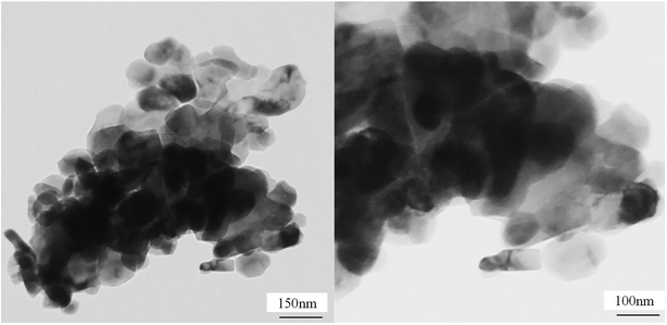
The solution combustion approach was chosen to prepare NiMo/Al2O3 catalysts with various amounts of fuel to oxidant molar ratio. The synthesis procedure is schematically shown in Fig. 1S in ESI.† First, a separate amount of (NH4)6Mo7O24·4H2O (22 wt% MoO3) and Ni(NO3)2(H2O)6 (5 wt% NiO), as Mo and Ni precursors, were dispersed in the minimum volume of distilled water, followed by magnetic stirring to achieve an aqueous solution. Next, γ-alumina powder was mixed with solution and stirred for 60 min at room temperature. In the next stage the fuel was supplied by adding the citric acid to the mixture with fuel/oxidant molar ratios of 0.5, 1, 2, 4. For this reason, 0.42, 0.85, 1.65 and 3.39 g of citric acid was added to the slurry, respectively, which was calculated using eqn (1) and (2).The solution was kept under stirring at ambient temperature for 1 h. Then the ammonia solution was used under stirring to adjust the pH of the mixture to 7. The slurry was maintained on a hot plate with continuous stirring at about 70 °C to evaporate all excess water to obtain a viscous gel. Afterward, the fuel-based gel was combusted in a crucible which placed in an electric furnace at 550 °C under air atmosphere. The reaction performed in a few minutes. Consequently, fluffy black powder was obtained. Ultimately, to burn off the remaining carbon species, the as-combusted samples were calcined at 550 °C for 4 h. The NiMo/Al2O3 catalysts are named as NMACA-x, where x is fuel/oxidant molar ratios of 0.5, 1, 2, 4.
The chemical equation during the combustion process for each of the species by considering H2O, CO2 and N2 as the reaction gases are as follows:
| Ni(NO3)2·6H2O + 2φC6H8O7·H2O + (9φ − 5/2)O2 → NiO + N2 + (10φ + 6)H2O + 12φCO2 | (1) |
| (NH4)6Mo7O24·4H2O + 2φC6H8·H2O + (9φ + 9/2)O2 → 7MoO3 + 3N2 + (10φ + 16)H2O + 12φCO2 | (2) |
2.3 Nanocatalyst characterizations
Phase identification and structure of catalysts were investigated by XRD analysis using an X'Pert MPD diffractometer (Philips, Netherland) with Co-Kα radiation (λ = 0.178897 nm) and input voltage of 40 kV. In order to investigate the morphology of prepared catalysts, FE-SEM analysis was carried out using S4160 (HITACHI, Japan). Surface element composition was detected by energy dispersive X-ray spectrometry (EDX) using a VEGA\\TESCAN-LMU apparatus. The transmission electron microscopy (TEM) analysis was performed by a Philips CM300 device, to evaluate the dispersion of active metals on alumina. To investigate the textural properties of the metal oxide samples, nitrogen adsorption–desorption isotherms data were recorded by the Micrometric (USA) instrument. The surface areas of the obtained samples were calculated by the Brunauer–Emmett–Teller (BET) analysis. Moreover, t-plot method was used to estimate the external surface area. To study the thermal decomposition of the dried gels, thermogravimetry analysis was performed using a TGA 209 F3Tarsus instrument. This examination is carried out in air atmosphere from room temperature to 600 °C with a heating rate of 10 °C min−1. The reducibility behaviour of supported metal oxide was evaluated by temperature-programmed reduction (H2-TPR) using a BELCAT (Japan) instrument.2.4 Experimental apparatus for HDS performance test
Before the hydrodesulfurization process, the prepared catalysts were sulfided by 7 wt% CS2-heptane mixture as follows: 2 g catalyst was loaded in the middle of the continuous fixed-bed reactor bounded by two pieces of quartz wool. The sulfidation process was conducted at atmospheric pressure for 3 h at 400 °C under hydrogen (120 ml min−1) and nitrogen (50 ml min−1) flows.Catalytic performance toward HDS reactions has been carried out in a slurry reactor using 3.5 wt% thiophene diluted in decane as a sulfur model compound. The HDS reactor configuration is schematically displayed in Fig. 2S in ESI.† The reactor was loaded with 20 mg of sulfided synthesized catalyst and 25 ml decane solution containing the sulfur compound. During the reactions, the hydrogen stream was sparged into the reactor (50 cm3 min−1). The HDS reaction was conducted at 55 and 105 °C at atmospheric pressure. In order to investigate the effect of residence time on catalytic activity, the experiments were done in two times of 15 and 30 minutes. The concentration of sulfur in the feed and products has been analyzed by a gas chromatography (Teif Gostar Faraz, Iran) equipped with a DB-1 column (Agilent) and flame ionization detector (Agilent). Conversion of thiophene was used to evaluate a catalytic activity in HDS reaction, which was measured by the following equation:
![[thin space (1/6-em)]](https://www.rsc.org/images/entities/char_2009.gif) 000 ppm) and C is the thiophene content in the treated product.
000 ppm) and C is the thiophene content in the treated product.
3 Results and discussions
3.1 Characterization of Ni–Mo/Al2O3 nanocatalyst
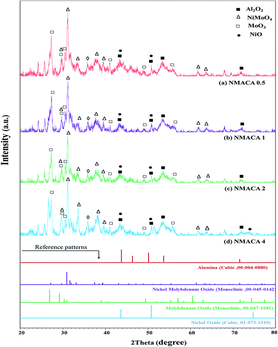 | ||
| Fig. 1 XRD patterns of NiMo/Al2O3 catalysts with various fuel content (a) NMACA0.5 (b) NMACA1 (c) NMACA2 (d) NMACA4. | ||
A series of diffraction peaks at about 26.79, 29.12, 30.24, 30.8, 49.37 and 56.92° could be ascribed to the formation of monoclinic molybdenum oxide (JCPDS 00-047-1081), which was present in the all samples. Furthermore, the reflection peaks at 2θ = 27.19, 30.96, 31.98, 33.18, 37.5, 39.38, 61.39 and 63.54° are assigned to the monoclinic crystalline phase NiMoO4 (JCPDS no. 00-045-0142). The analysis also reveals that in the case of NMACA4 the intensity of reflection at 31.9° increases, which is the active phase in the HDS reactions.
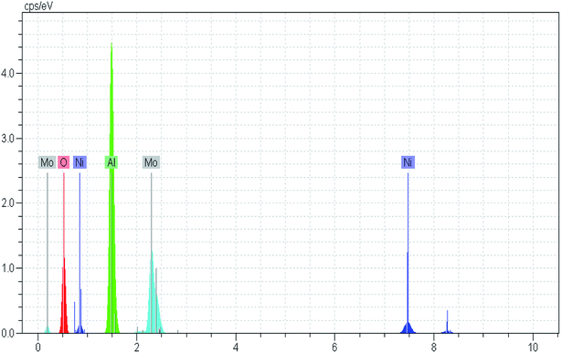
Costa et al.,30 reported that increasing fuel content leads to prolonged reaction flame time, and subsequently alter the specific characteristics of the obtained products. In this regard, in the case of NMACA4, time of combustion is sufficient to crystallize active phase. It is worth mentioning that, the crystallites bigger than 2–5 nm can be detected by XRD.4 The presence of peaks assigned to the NiMoO4 and MoO3 which are the precursors for the generation of Ni–Mo–S active site, propose the formation of well-crystallized of those phases. This result is in line with former investigation.4 In addition, the presence of metal species deposited on the alumina surface in the case of the NMACA4 catalyst was investigated using EDX analysis and the result is shown in Fig. 2. According to this figure, the existence of nickel, molybdenum, oxygen and aluminum species was confirmed.
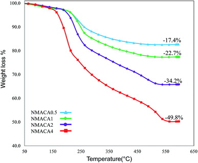
The weight loss below 200 °C can be assigned to the removal of physically adsorbed moisture.41 The sharp decrease in the sample weight above 200 °C is due to different chemical reactions, for example, dehydration–decomposition of deposited Ni and Mo precursors and further combustion of citric acid which are similar to previous reports.33,42
Through the combustion process, different successive stages including melting, dissolution and some chemical reactions occur to transform the fuel and the Ni and Mo precursors structure from an amorphous phase to a crystalline phase.43 This phenomenon is confirmed by XRD analysis. Furthermore, the combustion type varies from flaming to smoldering as the fuel content increased.41 Results from TGA patterns showed that the total weight loss over the NMACA0.5, NMACA1, NMACA2 and NMACA4 is 17.39, 22.69, 34.19 and 49.76 wt%, respectively. Based on the obtained results, amount of weight loss enhanced proportionally with increasing fuel to oxidant ratio. It can be concluded that when higher fuel content was used, more gaseous products was released. Similar results have been obtained by Mendoza-Nieto et al.,5 They reported that using of citric acid resulted in better dispersion of NiMoW over SBA-15 and led to remarkable improvement in HDS of dibenzothiophenes.
The absence of weight loss above 550 °C indicated that all the organic species the prepared gel would be decomposed with calcination in the air stream at 550 °C. So, that temperature was chosen for the calcination of the synthesized NiMo catalysts.
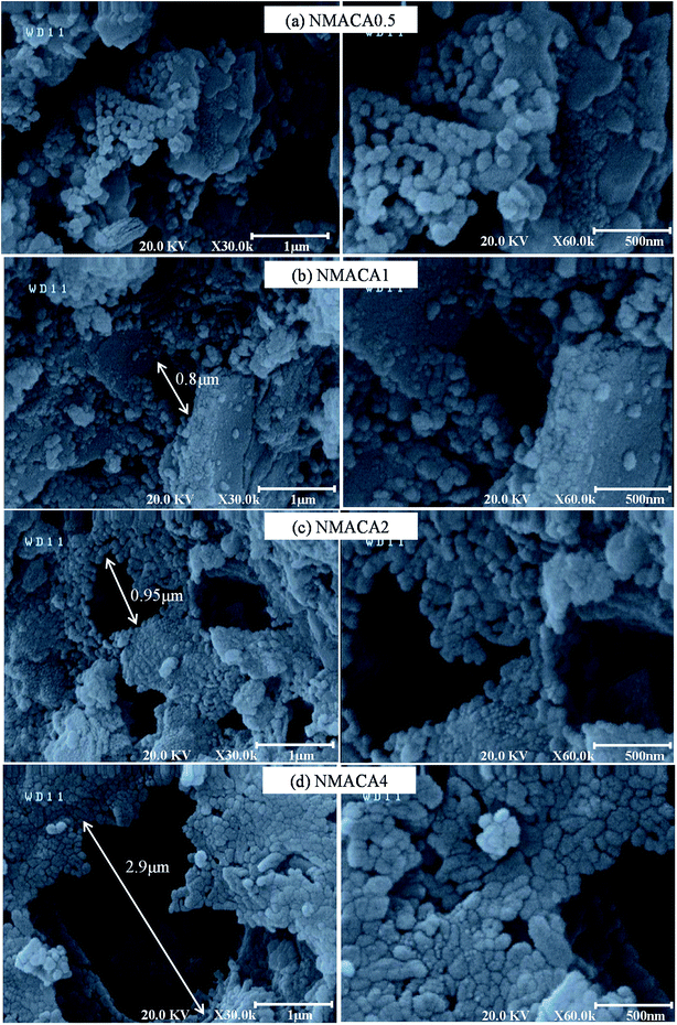 | ||
| Fig. 4 FESEM images of NiMo/Al2O3 catalysts synthesized with various fuel content (a) NMACA0.5, (b) NMACA1, (c) NMACA2, (d) NMACA4. | ||
The above observation revealed that the change in fuel to oxidant ratio has an outstanding effect on the porosity of synthesized catalysts. The highest porous morphology was achieved for the NMACA4 sample. The more gaseous product is released, the more open space between the particles will be created. This result is confirmed by TGA analysis, which demonstrated the linear relationship between weight loss and fuel content.
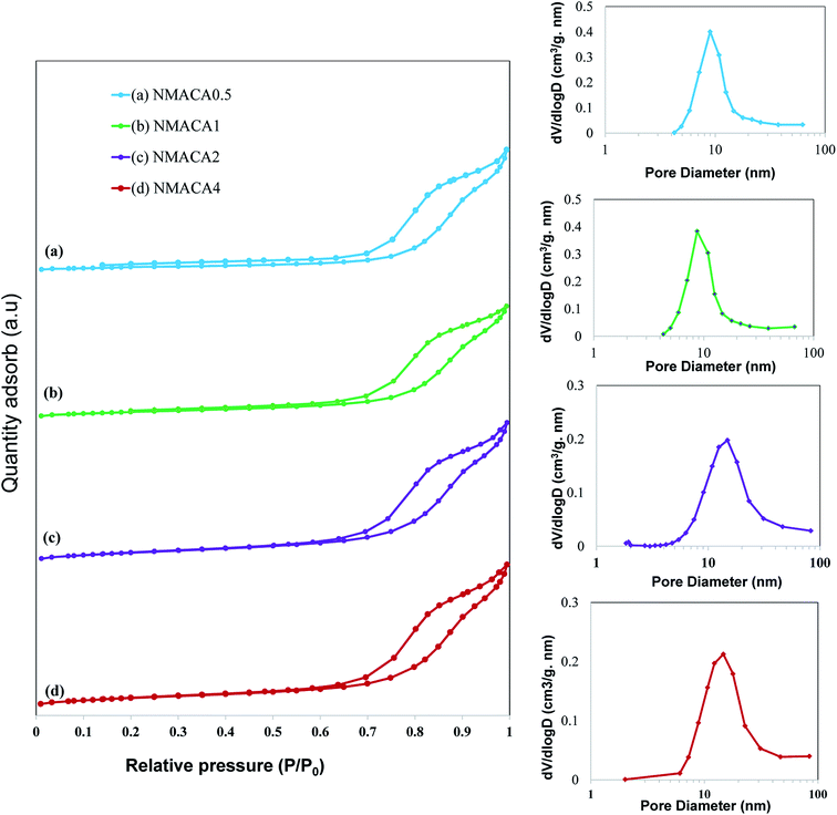
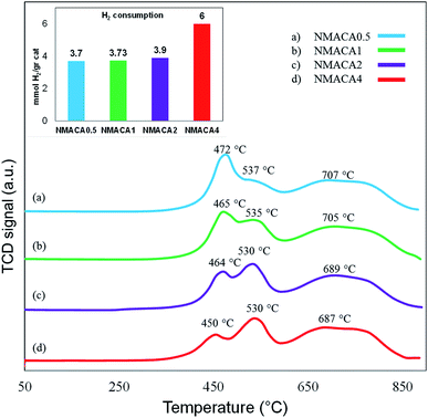
As can be seen in Fig. 6, all the samples show type IV isotherms with H3 hysteresis loop which confirms the slit-shaped mesoporous structure of the catalysts.47,48 Little adsorption at low relative pressure (below 0.2) can be attributed to the micropores, while adsorption at relative pressure above 0.7 originated from the presence of mesopores.35 A similar result was obtained by Obeso-Estrella et al.49 Furthermore, the pore diameter distribution of the samples resulted from Barrett–Joyner–Halenda (BJH) calculation indicated narrow distributions at low fuel content. By increasing the fuel content, a shift to larger pore diameters has obtained in the case of NMACA2 and NMACA4, yielding a broaden pore diameter distribution. This result evidences the existence of remarkable amount of mesopores which made the prepared samples suitable for the reactions containing large molecules. This phenomenon is well in agreement with Yousefi et al.48 report, who synthesized MgO/MgAl2O4 via microwave combustion method using various fuels.
In order to better understanding the textural characteristics of the support and NMACA-x catalysts, the porosity properties including the mesoporous volume (Vmeso), total pore volume (Vt), external surface area (Sext) and the BET surface area (SBET) are summarized in Table 1. According to this table, the BET surface area and the total pore volume of the alumina sample are 56 m2 g −1 and 0.182 cm3 g−1, respectively. The BET surface areas of the as-combusted NMACA-x series enhanced in the order shown: NMACA0.5 (25 m2 g−1) < NMACA1 (27 m2 g−1) < NMACA2 (37 m2 g−1) < NMACA4 (38 m2 g−1). It is widely known that the higher surface area facilitates catalytic reactions by affecting the adsorption of the reactant molecules on the metal active phases. By comparing the textural properties of the support and NMACA-x catalysts, it can be concluded that NMACA-x catalysts have remarkably smaller textural properties than the corresponding support. This observation pointed out some of the support pores were blocked during the deposition of metal species. This observation is well in consistent with our previous research,50 where a series of CuO–ZnO–Al2O3/ZSM-5 catalysts were fabricated via solution combustion approach and used in the dimethyl ether production reaction. As listed in Table 1, the external surface areas of the NMACA0.5, NMACA1, NMACA2 and NMACA4 are 14, 22, 33 and 31 m2 g−1, respectively. Results revealed that the fuel content has an outstanding impact on the porous properties of the catalysts. The mesopore volume of the NMACA0.5, NMACA1, NMACA2 and NMACA4 is equal to 0.096, 0.101, 0.117 and 0.120 cm3 g−1, respectively. The positive effect of employing higher fuel to oxidant ratio on the textural properties is explained by the higher amount of released gases during the combustion process as evidenced by FESEM analysis.
| SBET (m2 g−1) | Sexta (m2 g−1) | Vtb (cm3 g−1) | Vmesoc (cm3 g−1) | |
|---|---|---|---|---|
| a t-Plot external surface area.b Volume adsorbed at P/P0 = 0.99.c Mesopore volume (Vtotal − Vmicro). | ||||
| Al2O3 | 56.7 | 50.8 | 0.184 | 0.182 |
| NMACA0.5 | 25.9 | 14.9 | 0.098 | 0.096 |
| NMACA1 | 27.4 | 22.8 | 0.103 | 0.101 |
| NMACA2 | 37.7 | 33.1 | 0.119 | 0.117 |
| NMACA4 | 38.1 | 31.9 | 0.122 | 0.120 |
Consequently, the increase of fuel content was beneficial to adjusting the metal–support interactions, which can improve hydrogenation reaction as stated by the previous studies.16,54
3.2 Comparative performance of nanocatalysts toward HDS reaction
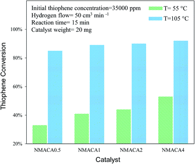 | ||
| Fig. 8 Catalytic activity of NiMo/Al2O3 with various fuel content toward hydrodesulfurization of thiophene at 15 min. | ||
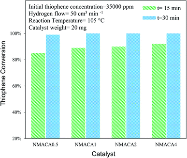 | ||
| Fig. 9 Catalytic activity of NiMo/Al2O3 with various fuel content toward hydrodesulfurization of thiophene at 105 °C. | ||
| Catalysts | Reactor type | Sulfur concentration (ppm) | Sulfur compound | Reaction conditions | Conversion | Ref. |
|---|---|---|---|---|---|---|
| CoMoW/Al2O3–TiO2 | Batch | 2260 | Thiophene | T = 320 °C | 85% | 49 |
| P = 55 atm | ||||||
| NiMo/Al2O3 | Fixed bed | 5000 | Dibezothiophene | T = 300 °C | 95% | 9 |
| P = 30 atm | ||||||
| Co–Mo–Ni/TiO2–Al2O3 | Fixed bed | 1500 | Thiophene | T = 74 °C | 80% | 60 |
| P = 35 atm | ||||||
| AlCNFMoCo | Batch | 550 | Dibezothiophene | T = 300 °C | 99% | 17 |
| P = 55 atm | ||||||
| NiMoW/Al2O3 | Batch | 1300 | 4,6-Dimethyldibenzothiophene | T = 300 °C | 69% | 5 |
| P = 73 atm | ||||||
| NiMo/Al2O3–ZrO2 | Batch | 10![[thin space (1/6-em)]](https://www.rsc.org/images/entities/char_2009.gif) 000 000 |
Thiophene | T = 160 °C | 99% | 18 |
| P = 1 atm | ||||||
| NiMoW/FMWCNT | Batch | 10![[thin space (1/6-em)]](https://www.rsc.org/images/entities/char_2009.gif) 000 000 |
Thiophene | T = 160 °C | 100% | 27 |
| P = 1 atm | ||||||
| AlMoCoB5% | Batch | 650 | Dibezothiophene | T = 300 °C | 98% | 61 |
| P = 50 atm | ||||||
| FeMoS/Al2O3 and carbon | Batch | 1000 | Thiophene | T = 280 °C | 30% | 62 |
| P = 1 atm | ||||||
| NiMo/Al2O3 | Batch | 35![[thin space (1/6-em)]](https://www.rsc.org/images/entities/char_2009.gif) 000 000 |
Thiophene | T = 105 °C | 100% | This work |
| P = 1 atm |
| T + Δ ↔ TΔ |
| H2 + 2θ ↔ 2Hθ |
| TΔ + 2Hθ → B + SΔ + 2θ |
| SΔ + H2 → H2S + Δ |
In the above equations, (B) referred to butadiene which can react further to butenes and butane in kinetically negligible steps. The rate-determining step is considered as the surface reaction between adsorbed hydrogen atom and thiophene with producing butadiene. The hydrogenation of butadiene to butenes and butane is regarded kinetically irrelevant.56 The main products for the thiophene HDS are butene and butane which are produced by carbon–sulfur scission of thiophene. Also, 2,3-dihydrothiophene, 2,5-dihydrothiophene and tetrahydrothiophene are important intermediates that can be produced in the reaction mechanism.59 It is interesting to note that the obtained products depend on the reaction conditions. For example, tetrahydrothiophene is a major intermediate at low temperature and high pressure, but may not be appeared at atmospheric pressure.27
4 Conclusions
NiMo/Al2O3 nanocatalysts were fabricated by the solution combustion method and the effect of various fuel to oxidant molar ratios of 0.5, 1, 2 and 4 were investigated. The formation of MoO3 and NiMoO4 as the crystalline phase over alumina were confirmed by XRD analysis. According to FESEM and TGA analyses with increasing fuel content, the amount of surface holes and weight loss were enhanced proportionally. The resulted data from nitrogen adsorption–desorption demonstrated that porous properties of the as-combusted catalysts were significantly dependent upon the amount of fuel used. Based on TPR results hydrogen consumption increases with enhancing the fuel/oxidant ratio. Furthermore, the peak position shifted to a relatively lower temperature, indicating more reducible species as well as weakened metal–support interaction. The catalytic activity of prepared samples was evaluated in hydrodesulfurization of thiophene. It was found that the catalysts synthesized with fuel/nitrate = 4 showed higher activity than other three catalysts under moderate operation condition (T = 55, 105 °C and t = 15 min). Further increase of reaction time from 15 to 30 min led to 100% conversion of thiophene for NMACA1, NMACA2 and NMACA4 samples. The considerable point in the current study was the utilization of a fast, simple and cost-effective approach for the fabrication of the NiMo/Al2O3 catalysts used in HDS process which represented good performance in harsh operating conditions.Conflicts of interest
There are no conflicts to declare.References
- M. S. Rana, J. Ancheyta, S. K. Maity and P. Rayo, Catal. Today, 2005, 109, 61–68 CrossRef CAS.
- P. T. Vasudevan and J. L. G. a. Fierro, Catal. Rev., 1996, 38, 161–188 CrossRef CAS.
- S. Brunet, D. Mey, G. Pérot, C. Bouchy and F. Diehl, Appl. Catal., A, 2005, 278, 143–172 CrossRef CAS.
- H. Wang, Z. Yang, F. Meng, W. Yin and Y. Wu, Fuel, 2018, 228, 332–341 CrossRef CAS.
- J. A. Mendoza-Nieto, F. Robles-Méndez and T. E. Klimova, Catal. Today, 2015, 250, 47–59 CrossRef CAS.
- A. Tanimu and K. Alhooshani, Energy Fuels, 2019, 33, 2810–2838 CrossRef CAS.
- O. G. Salnikov, D. B. Burueva, D. A. Barskiy, G. A. Bukhtiyarova, K. V. Kovtunov and I. V. Koptyug, ChemCatChem, 2015, 7, 3508–3512 CrossRef CAS.
- Y. Huang, Z. Zhou, Y. Qi, X. Li, Z. Cheng and W. Yuan, Chem. Eng. J., 2011, 172, 444–451 CrossRef CAS.
- L. Yang, C. Peng, X. Fang, Z. Cheng and Z. Zhou, Catal. Commun., 2019, 121, 68–72 CrossRef CAS.
- M. S. Rana, B. N. Srinivas, S. K. Maity, G. M. Dhar and T. S. R. P. Rao, J. Catal., 2000, 195, 31–37 CrossRef CAS.
- M. Ebrahiminejad and R. Karimzadeh, Adv. Powder Technol., 2019, 30, 1450–1461 CrossRef CAS.
- C. E. Santolalla-Vargas, V. A. S. Toriello, J. A. De los Reyes, D. K. Cromwell, B. Pawelec and J. L. G. Fierro, Mater. Chem. Phys., 2015, 166, 105–115 CrossRef CAS.
- K. V. R. Chary, K. R. Reddy, G. Kishan, J. W. Niemantsverdriet and G. Mestl, J. Catal., 2004, 226, 283–291 CrossRef CAS.
- J. Whelan, M. S. Katsiotis, S. Stephen, G. E. Luckachan, A. Tharalekshmy, N. D. Banu, J.-C. Idrobo, S. T. Pantelides, R. V. Vladea and I. Banu, Energy Fuels, 2018, 32, 7820–7826 CrossRef CAS.
- G. M. Dhar, B. N. Srinivas, M. S. Rana, M. Kumar and S. K. Maity, Catal. Today, 2003, 86, 45–60 CrossRef CAS.
- Y. Wang, B. Shen, J. Li, B. Feng, X. Li, S. Ren and Q. Guo, Fuel Process. Technol., 2014, 128, 166–175 CrossRef CAS.
- S. A. Al-Hammadi, A. M. Al-Amer and T. A. Saleh, Chem. Eng. J., 2018, 345, 242–251 CrossRef CAS.
- P. Jabbarnezhad, M. Haghighi and P. Taghavinezhad, Fuel Process. Technol., 2014, 126, 392–401 CrossRef CAS.
- M. A. Ali and S. Asaoka, J. Pet. Sci. Technol., 2009, 27, 984–997 CrossRef CAS.
- M. Ebrahimynejad and M. Haghighi, J. Pet. Sci. Technol., 2014, 32, 2867–2877 CrossRef CAS.
- H. Ajamein, M. Haghighi and S. Alaei, Energy Convers. Manag., 2017, 137, 61–73 CrossRef CAS.
- X. Li, K. Qiao, F. Subhan, W. Xing, X. Liu and Z. Yan, Appl. Petrochem. Res., 2015, 5, 405–411 CrossRef.
- S. Badoga, K. C. Mouli, K. K. Soni, A. K. Dalai and J. Adjaye, Appl. Catal., B, 2012, 125, 67–84 CrossRef CAS.
- M. Sun, D. Nicosia and R. Prins, Catal. Today, 2003, 86, 173–189 CrossRef CAS.
- C. Kordulis, A. A. Lappas, C. Fountzoula, K. Drakaki, A. Lycourghiotis and I. A. Vasalos, Appl. Catal., A, 2001, 209, 85–95 CrossRef CAS.
- Y. Okamoto, A. Kato, N. Rinaldi, T. Fujikawa, H. Koshika, I. Hiromitsu and T. Kubota, J. Catal., 2009, 265, 216–228 CrossRef CAS.
- S. Ashenaeian, M. Haghighi and N. Rahemi, Adv. Powder Technol., 2019, 30, 502–512 CrossRef CAS.
- Y. Okamoto, S.-y. Ishihara, M. Kawano, M. Satoh and T. Kubota, J. Catal., 2003, 217, 12–22 CAS.
- M. V. Landau, L. Vradman, M. Herskowitz, Y. Koltypin and A. Gedanken, J. Catal., 2001, 201, 22–36 CrossRef CAS.
- A. C. F. M. Costa, M. R. Morelli and R. H. G. A. Kiminami, J. Mater. Synth. Process., 2001, 9, 347–352 CrossRef CAS.
- K. Tahmasebi and M. H. Paydar, J. Alloys Compd., 2011, 509, 1192–1196 CrossRef CAS.
- S. L. González-Cortés, T.-C. Xiao, T.-W. Lin and M. L. H. Green, Appl. Catal., A, 2006, 302, 264–273 CrossRef.
- S. L. Gonzalez-Cortes, S. M. A. Rodulfo-Baechler, T. Xiao and M. L. H. Green, Catal. Lett., 2006, 111, 57–66 CrossRef CAS.
- S. L. González-Cortés, T.-C. Xiao, P. M. F. J. Costa, B. Fontal and M. L. H. Green, Appl. Catal., A, 2004, 270, 209–222 CrossRef.
- H. Fathi, S. M. Masoudpanah, S. Alamolhoda and H. Parnianfar, Ceram. Int., 2017, 43, 7448–7453 CrossRef CAS.
- V. D. Sudheesh, N. Thomas, N. Roona, H. Choudhary, B. Sahoo, N. Lakshmi and V. Sebastian, J. Alloys Compd., 2018, 742, 577–586 CrossRef CAS.
- S. Yousefi, M. Haghighi and B. R. Vahid, Chem. Eng. Res. Des., 2018, 138, 506–518 CrossRef CAS.
- A. Manikandan, J. J. Vijaya, J. A. Mary, L. J. Kennedy and A. Dinesh, J. Ind. Eng. Chem., 2014, 20, 2077–2085 CrossRef CAS.
- M. Radpour, S. Alamolhoda and S. M. Masoudpanah, Ceram. Int., 2017, 43, 13729–13734 CrossRef CAS.
- X. Zhang, D. Han, Z. Hua and S. Yang, J. Alloys Compd., 2016, 684, 120–124 CrossRef CAS.
- W. Lai, L. Pang, J. Zheng, J. Li, Z. Wu, X. Yi, W. Fang and L. Jia, Fuel Process. Technol., 2013, 110, 8–16 CrossRef CAS.
- H. Knözinger and P. Ratnasamy, Catal. Rev. - Sci. Eng., 1978, 17, 31–70 CrossRef.
- A. Varma, A. S. Mukasyan, A. S. Rogachev and K. V. Manukyan, Chem. Rev., 2016, 116, 14493–14586 CrossRef CAS PubMed.
- H. Palneedi, V. Mangam, S. Das and K. Das, J. Alloys Compd., 2011, 509, 9912–9918 CrossRef CAS.
- Y. Boukoberine and B. Hamada, Arabian J. Chem., 2016, 9, S522–S527 CrossRef CAS.
- F. Liu, S. Xu, L. Cao, Y. Chi, T. Zhang and D. Xue, J. Phys. Chem., 2007, 111, 7396–7402 CAS.
- S. Safari, R. Khoshbin and R. Karimzadeh, RSC Adv., 2019, 9, 16797–16811 RSC.
- H. Nayebzadeh, M. Haghighi, N. Saghatoleslami, M. Tabasizadeh and S. Yousefi, Energy Convers. Manag., 2018, 171, 566–575 CrossRef CAS.
- R. Obeso-Estrella, J. L. G. Fierro, J. N. D. De Leon, S. Fuentes, G. Alonso-Nuñez, E. Lugo-Medina, B. Pawelec and T. A. Zepeda, Fuel, 2018, 233, 644–657 CrossRef CAS.
- R. Khoshbin, M. Haghighi and P. Margan, Energy Convers. Manag., 2016, 120, 1–12 CrossRef CAS.
- L. Peña, D. Valencia and T. Klimova, Appl. Catal., B, 2014, 147, 879–887 CrossRef.
- Q. Cui, Y. Zhou, Q. Wei, G. Yu and L. Zhu, Fuel Process. Technol., 2013, 106, 439–446 CrossRef CAS.
- H. Topsøe, B. S. Clausen, R. Candia, C. Wivel and S. Mørup, J. Catal., 1981, 68, 433–452 CrossRef.
- S. Bendezú, R. Cid, J. L. G. Fierro and A. L. Agudo, Appl. Catal., A, 2000, 197, 47–60 CrossRef.
- H. Wang and E. Iglesia, ChemCatChem, 2011, 3, 1166–1175 CrossRef CAS.
- R. Doukeh, M. Bombos, A. Trifoi, O. Mihai, D. Popovici, I. Bolocan and D. Bombos, C. R. Chim., 2018, 21, 277–287 CrossRef CAS.
- R. Prins, V. H. J. De Beer and G. A. Somorjai, Catal. Rev., 1989, 31, 1–41 CrossRef CAS.
- A. Borgna, E. J. M. Hensen, J. A. R. van Veen and J. W. Niemantsverdriet, J. Catal., 2004, 221, 541–548 CrossRef CAS.
- E. J. M. Hensen, M. J. Vissenberg, V. H. J. de Beer, J. A. R. van Veen and R. A. van Santen, J. Catal., 1996, 163, 429–435 CrossRef CAS.
- C. Liu, Z. Zhou, Y. Huang, Z. Cheng and W. Yuan, Chin. J. Chem. Eng., 2014, 22, 383–391 CrossRef CAS.
- T. A. Saleh, S. A. Al-Hammadi and A. M. Al-Amer, Process Saf. Environ. Prot., 2019, 121, 165–174 CrossRef CAS.
- R. Hubaut, J. Altafulla, A. Rives and C. Scott, Fuel, 2007, 86, 743–749 CrossRef CAS.
Footnote |
| † Electronic supplementary information (ESI) available. See DOI: 10.1039/d0ra01590c |
| This journal is © The Royal Society of Chemistry 2020 |


