 Open Access Article
Modified graphene supported Ag–Cu NPs with enhanced bimetallic synergistic effect in oxidation and Chan–Lam coupling reactions†
Nitika Sharma,
Anu Choudhary,
Manpreet Kaur,
Chandan Sharma,
Satya Paul * and
Monika Gupta
Department of Chemistry, University of Jammu, Jammu Tawi-180006, India. E-mail: paul7@rediffmail.com
First published on 14th August 2020
Abstract
Herein, well dispersed Ag–Cu NPs supported on modified graphene have been synthesized via a facile and rapid approach using sodium borohydride as a reducing agent under ambient conditions. Dicyandiamide is selected as an effective nitrogen source with TiO2 as an inorganic material to form two kinds of supports, labelled as TiO2–NGO and NTiO2–GO. Initially, the surface area analysis of these two support materials was carried out which indicated that N-doping of GO followed by anchoring with TiO2 has produced support material of larger surface area. Using both types of supports, ten nano-metal catalysts based on Ag and Cu were synthesized. Benefiting from the bimetallic synergistic effect and larger specific surface area of TiO2–NGO, Cu@Ag–TiO2–NGO is found to be a highly active and reusable catalyst out of other synthesized catalysts. It exhibits excellent catalytic activity for oxidation of alcohols and hydrocarbons as well as Chan–Lam coupling reactions. The nanocatalyst is intensively characterized by BET, SEM, HR-TEM, ICP-AES, EDX, CHN, FT-IR, TGA, XRD and XPS.
Introduction
Graphene inherits remarkable electronic, thermal, optical and mechanical properties, which make it attractive for use in the field of heterogeneous catalysis. However, due to aggregation1 between the layers of graphene, it has limited use in the field of catalysis. Graphene oxide (GO), generally obtained by the exfoliation of graphite2 has emerged as a new class of carbonaceous water-compatible heterogeneous catalysts.3–6 Mostly, graphene oxide (GO) and its derivatives have been used to synthesize graphene-supported nano-metal catalysts because of the presence of plentiful oxygenated functional groups and topological defects7 which serve as more favourable anchoring sites for the precursors.8Nowadays, heteroatom doping is extensively used to modify the properties of GO and particularly N-doped graphene has attracted sufficient scientific interest due to its alluring performance in supercapacitors,9 lithium-ion batteries,10 catalyst support11 and catalysis.12–14 Greater electronegativity of N as compared to C along with the conjugation between nitrogen lone pair of electrons and graphene π-system has found to tailor the electronic properties of N-doped graphene. Also, N-modified graphene has additional benefits of introducing basic character to the support material, which in turn stabilizes the metal nanoparticles as well as avoid the use of additional base in stoichiometric amount. Recently, several approaches have been reported in literature which indicates that introduction of nitrogen into graphene modulate its electronic as well as chemical properties and hence make N-G more catalytically active than graphene. For instance, Lin et al. have successfully prepared nitrogen doped graphene (NG) from GO and urea at 800 °C in an inert atmosphere, which has shown superior catalytic activity towards ORR than Pt/C catalysts.3 Urea reacts with oxygen-containing functional groups present in the GO, where N content was increased upto 46%. Xiong et al. have prepared N-doped graphene by thermal annealing of GO in ammonia at different temperatures and used it as a conductive support for Pt nanoparticles. The Pt/N-G catalysts showed tremendous electrocatalytic activity towards methanol oxidation as compared to undoped catalysts.4 This synergistic electrochemical effect was probably due to the existence of electronic interactions between Pt NPs and NG.
Further, to increase the surface area as well as thermal stability, graphene has been immobilized onto various inorganic materials such as silica, titania, zirconia, ceria etc. Zhang et al. prepared a photocatalyst from polyelectrolyte/exfoliated titania nanosheet/graphene oxide by flocculation and calcination. The polyelectrolyte, PDDA (poly-diallyl-dimethyl-ammonium chloride) acts as an effective binder to precipitate GO and titania nanosheets, thereby enhancing the overall performance of the catalyst significantly.5 Liu et al. successfully developed graphene-coated silica (GCS) which act as a highly efficient sorbent. The prevention of dispersion in water by the hydrophobic nature of graphene and adsorption capacity by agglomeration was overcome by coating it with silica.6 Among various inorganic materials, nano-TiO2 (ref. 15–17) has received increased attention owing to its exceptional properties such as non-toxicity, low cost and chemical stability as well as application in photocatalysis. Combining TiO2 with GO can facilitate the electron transfer as GO binds with TiO2 by forming coordinate bonds between functional groups and Ti4+ centers and thus increases the thermal stability.
Although a variety of heterogeneous catalysts have been reported in the literature for the oxidation of alcohols and hydrocarbons, and Chan–Lam coupling reactions, but the development of a novel, versatile and recyclable catalytic system employing mild and inexpensive reaction conditions is still a challenging job. Hence, based on the principle of green chemistry, we tried to develop a general and sustainable protocol for the selective liquid-phase oxidation of alcohols and hydrocarbons, and Chan–Lam coupling reactions. Further, the significant enhancement in the activity and selectivity of the synthesized catalyst was observed due to the presence of an interesting and innovative support material which turned out to be highly useful for the stabilization of MNPs as well as hamper the agglomeration and stacking of the GO sheets.
Keeping in view the above facts in mind, we have prepared two types of supports; one in which GO was first modified with nitrogen precursor, dicyandiamide (NGO) and then TiO2 was incorporated onto its surface i.e. TiO2–NGO, whereas in the other type, GO was modified with TiO2 first to get GO–TiO2 composite followed by doping with N using dicyandiamide to get nitrogen modified composite (NTiO2–GO). BET surface area analysis indicated that TiO2–NGO composite has larger surface area as compared to NTiO2–GO (Fig. 1). The existence of synergistic effect between NGO and TiO2 would increase the surface area available for adsorption and improve the surface exposure of the catalytic active sites. Finally, Ag–Cu nanoparticles (NPs) with varied metal composition were immobilized onto the support (TiO2–NGO and NTiO2–GO) so as to obtain ten nanometal catalysts which were tested for the oxidation of alcohols and hydrocarbons, and Chan–Lam coupling reactions.
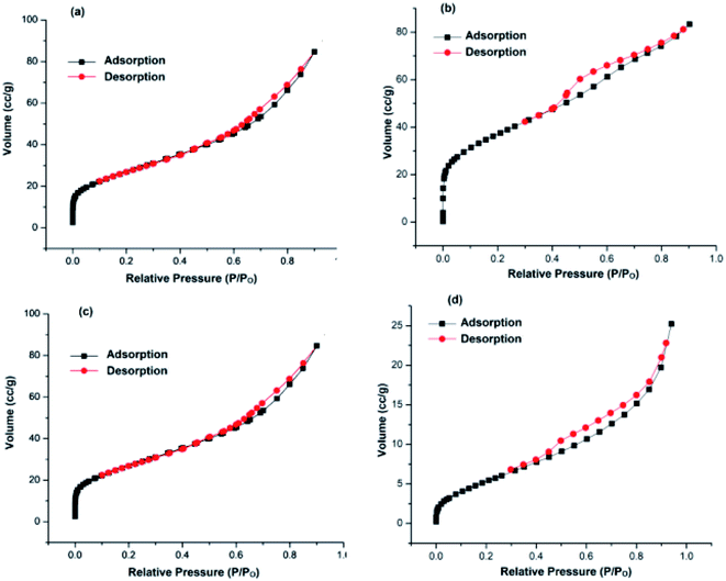 | ||
| Fig. 1 N2 adsorption–desorption isotherms of: (a) TiO2–NGO; (b) NTiO2–GO; (c) Cu@Ag–TiO2–NGO; (d) Cu@Ag–NTiO2–GO. | ||
Hence, the main aim of the present work was to get insight into the role of N-doping for the stabilization of metal nanoparticles and to explore the mechanism behind the synergism between Ag–Cu NPs using different spectral studies. Out of the various catalysts synthesized, Cu@Ag–TiO2–NGO showed superior activity for oxidations as well as for Chan–Lam coupling and was fully characterized by several comprehensive techniques such as BET, SEM, HR-TEM, ICP-AES, EDX, CHN, FT-IR, TGA, XRD and XPS.
Experimental
Materials and characterization
The chemicals used were obtained from Aldrich Chemical company and used further without purification. FTIR spectra of the catalysts were obtained on FTIR spectrometer (Agilent Technologies, L1600312 spectrum TWOLITA/ZnSe) while thermal stability of the prepared catalysts was measured by TGA analyzer (PerkinElmer, Diamond TG/DTA). XRD was obtained on a Bruker AXSD8 Advance X-ray diffractometer using Cu Kα radiations. SEM images were recorded using FEG SEM JSM-7600F Scanning Electron Microscope and HR-TEM images using FEG, Tecnai G2, F30 Transmission Electron Microscope. Actual loading of metal was determined by ICP-AES analysis using ARCOS, Simultaneous ICP spectrometer. EDX analysis was surveyed by using OXOFORD X-MAX Model JSM-7600F and XPS spectra of the catalysts were recorded on KRATOS ESCA model AXIS 165 (Resolution) while CHN analysis was carried out on Thermo Finnigan, FLASH EA 1112 series. BET (Brunauer–Emmett–Teller) specific surface area was determined from N2 adsorption–desorption isotherms using Belsorb Mini-X analyzer. The mass spectra were analysed by ESI-esquire 3000 Bruker Daltonics spectrometer while 1H NMR (400 MHz) and 13C NMR (100 MHz) spectra of the synthesized products were recorded using chloroform-d on Bruker Advance III spectrometer using TMS as an internal standard.Catalyst preparation
Synthesis of NTiO2–GO. NTiO2–GO composite was prepared by dispersing GO18 (1 g) into ethanol (40 mL) and ammonium hydroxide (5 mL) followed by ultrasonication for 1 h. This solution was then transferred into a round bottom flask (100 mL) and heated at 45 °C under continuous stirring for 12 h followed by the addition of solution of tetrabutyl orthotitanate (TBOT, 4 mL) in ethanol (30 mL) dropwise at a rate of 5 mL min−1. The resultant TiO2–GO composite was filtered, washed thoroughly with distilled water (5 mL), ethanol (5 mL), and dried in an oven at 60 °C. Dicyandiamide (1 g) was dispersed with TiO2–GO (2 g) in distilled water (100 mL) followed by stirring at room temperature overnight. Water from the well-dispersed suspension was removed, grey powdered hybrid material was obtained, which was first heated at a rate of 5 °C min−1 upto 200 °C, maintaining this temperature for 1 h and then, subsequently heating at 5 °C min−1 upto 350 °C for 8 h. The as-synthesized dark grey powder was the desired NTiO2–GO composite.
Synthesis of TiO2–NGO. Dicyandiamide (1 g) was mixed with GO (2 g) in distilled water (100 mL) and was stirred well. Water in the well-dispersed suspension was allowed to evaporate which resulted in grey powdered hybrid material. This hybrid material was first heated at a rate of 5 °C min−1 upto 200 °C, maintaining this temperature for 1 h and then, subsequently heating at 5 °C min−1 upto 350 °C for 8 h. The as-synthesized dark grey powder was the desired NGO support. Now, TiO2–NGO was prepared by ultrasonication of NGO (1 g) and ammonium hydroxide (5 mL) in ethanol (40 mL) for 1 h. The resultant solution was then transferred into a round bottom flask (100 mL) and heated at 45 °C for 12 h with stirring, followed by addition of tetrabutyl orthotitanate (TBOT, 4 mL) in ethanol (30 mL) at the rate of 5 mL min−1. TiO2–NGO composite formed was filtered, washed with distilled water, ethanol and finally dried in an oven at 60 °C overnight.
Synthesis of bimetallic Ag and Cu supported nano-metal catalysts. To a suspension of NTiO2–GO or TiO2–NGO (1 g) in ethanol
![[thin space (1/6-em)]](https://www.rsc.org/images/entities/char_2009.gif) :
:![[thin space (1/6-em)]](https://www.rsc.org/images/entities/char_2009.gif) water (1
water (1![[thin space (1/6-em)]](https://www.rsc.org/images/entities/char_2009.gif) :
:![[thin space (1/6-em)]](https://www.rsc.org/images/entities/char_2009.gif) 1, 10 mL), AgNO3 (0.169 g, 0.1 mmol) was added and the resulting mixture was stirred for 20 min. To this suspension, freshly prepared aqueous solution of NaBH4 (1.5 mmol, 5 mL) was added over a period of 1 h and the stirring was continued for 3 h at room temperature. Now, Cu(NO3)2 (0.241 g, 0.1 mmol) was added into the resultant mixture and further stirred for 20 min followed by addition of freshly prepared aqueous solution of NaBH4 (1.5 mmol, 5 mL) over a period of 1 h. After 12 h of continuous stirring, the catalyst (Cu@Ag–NTiO2–GO or Cu@Ag–TiO2–NGO) was recovered by filtration and effectively washed with distilled water (3 × 10 mL), ethanol (3 × 10 mL) and dried in vacuum at room temperature overnight. Similarly, Ag@Cu–NTiO2–GO or Ag@Cu–TiO2–NGO were prepared following the same procedure as mention above, but here Cu(NO3)2 (0.241 g, 0.1 mmol) was added first and then reduced, followed by the addition of AgNO3 (0.169 g, 0.1 mmol) which was later reduced by using NaBH4 solution. Cu–Ag alloy (Ag–Cu@TiO2–NGO or Ag–Cu@NTiO2–GO) was prepared by stirring NTiO2–GO or TiO2–NGO (1 g) in ethanol
1, 10 mL), AgNO3 (0.169 g, 0.1 mmol) was added and the resulting mixture was stirred for 20 min. To this suspension, freshly prepared aqueous solution of NaBH4 (1.5 mmol, 5 mL) was added over a period of 1 h and the stirring was continued for 3 h at room temperature. Now, Cu(NO3)2 (0.241 g, 0.1 mmol) was added into the resultant mixture and further stirred for 20 min followed by addition of freshly prepared aqueous solution of NaBH4 (1.5 mmol, 5 mL) over a period of 1 h. After 12 h of continuous stirring, the catalyst (Cu@Ag–NTiO2–GO or Cu@Ag–TiO2–NGO) was recovered by filtration and effectively washed with distilled water (3 × 10 mL), ethanol (3 × 10 mL) and dried in vacuum at room temperature overnight. Similarly, Ag@Cu–NTiO2–GO or Ag@Cu–TiO2–NGO were prepared following the same procedure as mention above, but here Cu(NO3)2 (0.241 g, 0.1 mmol) was added first and then reduced, followed by the addition of AgNO3 (0.169 g, 0.1 mmol) which was later reduced by using NaBH4 solution. Cu–Ag alloy (Ag–Cu@TiO2–NGO or Ag–Cu@NTiO2–GO) was prepared by stirring NTiO2–GO or TiO2–NGO (1 g) in ethanol![[thin space (1/6-em)]](https://www.rsc.org/images/entities/char_2009.gif) :
:![[thin space (1/6-em)]](https://www.rsc.org/images/entities/char_2009.gif) water (1
water (1![[thin space (1/6-em)]](https://www.rsc.org/images/entities/char_2009.gif) :
:![[thin space (1/6-em)]](https://www.rsc.org/images/entities/char_2009.gif) 1, 10 mL) for 20 min followed by addition of Cu(NO3)2 (0.241 g, 0.1 mmol) and AgNO3 (0.169 g, 0.1 mmol) simultaneously. Then, freshly prepared aqueous solution of NaBH4 (3.0 mmol, 10 mL) was added dropwise over a period of 1 h and the stirring was continued for 12 h at room temperature. After the metal NPs were synthesized, they were separated by filtration and washed with distilled water (3 × 10 mL) and ethanol (3 × 10 mL) respectively. The catalyst was dried in vacuum at room temperature overnight. Monometallic Cu@TiO2–NGO or Cu@NTiO2–GO and Ag@TiO2–NGO or Ag@NTiO2–GO were prepared by the similar methodology using Cu(NO3)2 (0.241 g, 0.1 mmol) and AgNO3 (0.169 g, 0.1 mmol) respectively.
1, 10 mL) for 20 min followed by addition of Cu(NO3)2 (0.241 g, 0.1 mmol) and AgNO3 (0.169 g, 0.1 mmol) simultaneously. Then, freshly prepared aqueous solution of NaBH4 (3.0 mmol, 10 mL) was added dropwise over a period of 1 h and the stirring was continued for 12 h at room temperature. After the metal NPs were synthesized, they were separated by filtration and washed with distilled water (3 × 10 mL) and ethanol (3 × 10 mL) respectively. The catalyst was dried in vacuum at room temperature overnight. Monometallic Cu@TiO2–NGO or Cu@NTiO2–GO and Ag@TiO2–NGO or Ag@NTiO2–GO were prepared by the similar methodology using Cu(NO3)2 (0.241 g, 0.1 mmol) and AgNO3 (0.169 g, 0.1 mmol) respectively.
General procedure for the oxidation of alcohols and hydrocarbons
For the oxidation, Cu@Ag–TiO2–NGO (0.1 g) was added to the mixture of alcohol or hydrocarbon (1 mmol) and TBHP (1 mmol) in ethanol (8 mL) and the reaction mixture was stirred at 70 °C for the desired time. Ethanol was then removed under reduced pressure followed by addition of ethyl acetate (20 mL). The catalyst was separated by filtration and washed with deionized water (2 × 10 mL), ethyl acetate (3 × 5 mL) respectively and dried under vacuum for further use. The organic layer was washed with deionized water (3 × 20 mL) followed by drying over anhydrous Na2SO4. Finally, the product was obtained by column chromatography on silica gel (60–120 mesh) using petroleum ether and ethyl acetate as eluting solvents.General procedure for Chan–Lam cross-coupling of aromatic amines with arylboronic acids
The mixture of aryl amine (1 mmol), arylboronic acid (1 mmol) and Cu@Ag–TiO2–NGO (0.1 g) in water (5 mL) was stirred at 80 °C for the appropriate time. Then, the catalyst was filtered off, washed with ethyl acetate (3 × 5 mL), deionized water (2 × 10 mL) and dried under vacuum. The filtrate was cooled to room temperature, diluted with ethyl acetate (20 mL) and washed with brine solution followed by drying over anhydrous Na2SO4. Column chromatography on silica gel (60–120 mesh) using ethyl acetate–petroleum ether as eluent was done to obtain the product.The structures of the products were confirmed by 1H and 13C NMR and mass spectral data.
Results and discussion
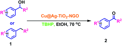
Herein, we report the synthesis of Ag–Cu bimetallic NPs decorated on modified GO and its activity was evaluated for the oxidation and C–N coupling reactions. Ten different catalysts based on immobilization of bimetallic Ag–Cu and monometallic Ag and Cu on modified GO were synthesized in order to study the synergism between two metals as well as effect of N-doping prior to and after modification of GO with TiO2. First of all, two different support materials, TiO2–NGO and NTiO2–GO were synthesized. In TiO2–NGO, GO was doped with nitrogen followed by anchoring of TiO2, whereas in NTiO2–GO, first anchoring of GO and TiO2 was carried out followed by nitrogen doping using dicyandiamide. Initially, the surface area analysis of these two support materials was carried out. The BET surface area of TiO2–NGO was found to be 132 m2 g−1 with pore volume of 0.1289 cm3 g−1, whereas NTiO2–GO has surface area 26.9 m2 g−1 with pore volume 0.0486 cm3 g−1.Thus, it is concluded that N-doping of GO followed by anchoring with TiO2 has produced support material of larger surface area. This was further supported by the BET surface area of synthesized Cu@Ag–TiO2–NGO as 98.0 m2 g−1 with total pore volume as 0.131 cm3 g−1, whereas Cu@Ag–NTiO2–GO as 21.3 m2 g−1 with total pore volume as 0.039 cm3 g−1 (Fig. 1). It has been rationalized that the surface area of the catalyst would be smaller as compared to that of the support as some surface of support was occupied by the well dispersed Ag–Cu nanoparticles. Initially, all catalysts were tested for oxidation (entry 2a, Table 3) and Chan–Lam coupling (entry 5c, Table 6) and found that Cu@Ag–TiO2–NGO was the best among all the synthesized catalysts and so was fully characterized by BET, SEM, HR-TEM, ICP-AES, EDX, CHN, FT-IR, TGA, XRD and XPS.
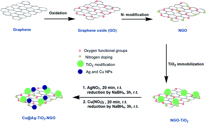
An illustration of the preparation protocol for Cu@Ag–TiO2–NGO is shown in Scheme 1. GO was firstly prepared by Hummer's method followed by its thermal annealing with dicyandiamide, which resulted in spontaneous conversion of graphene oxide into nitrogen doped graphene oxide. Further, in order to increase the thermal stability and surface area of modified graphene oxide, it was immobilized with TiO2. Finally, Ag(0) and Cu(0) nanoparticles were in situ synthesized and immobilized onto the support and then fully characterized by several comprehensive techniques in order to determine their physicochemical compositions.
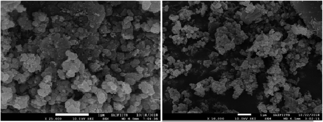
The surface morphology of the catalyst was determined by Field Emission Gun Scanning Electron Microscopy (FEG-SEM) which clearly indicates that TiO2 embedded on GO sheets was almost spherical in shape and distributed throughout its surface (Fig. 2). This spherical shape avoids agglomeration, which increases the surface area of the catalyst as well as its catalytic activity.
HR-TEM micrographs of Cu@Ag–TiO2–NGO (Fig. 3a and b) confirmed the layered structure of GO with several 2D stacked graphene sheets decorated by spherical TiO2 nanoparticles, signifying a successful negative–positive electrostatic attraction mechanism.19 The dark mesh on titania particles and GO sheets confirmed that the nanoparticles were evenly dispersed on the support surface. The histogram (Fig. 3c) shows an average size of metal nanoparticles as 15–20 nm, while the corresponding SAED pattern (Fig. 3d) shows concentric rings and dots which indicated that the nanoparticles are polycrystalline in nature.
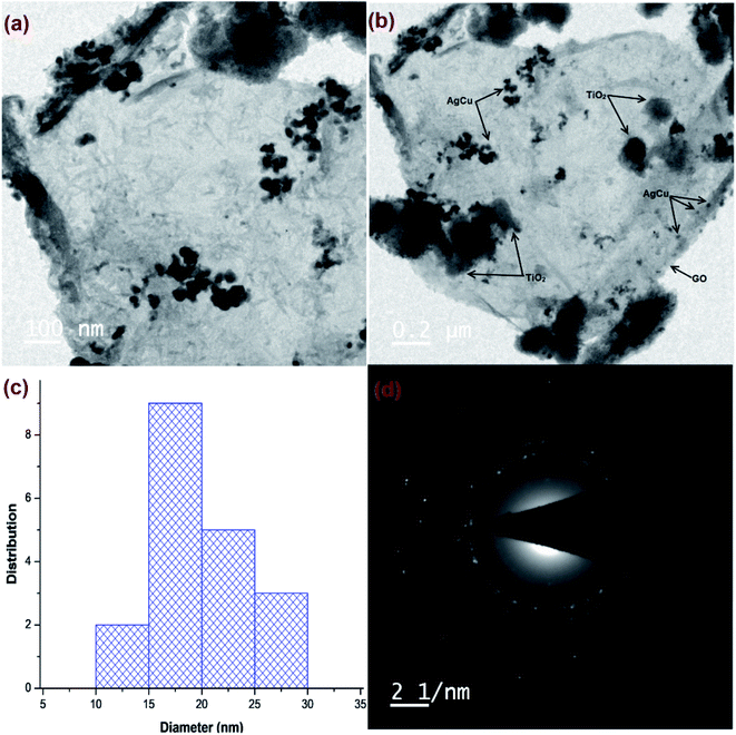 | ||
| Fig. 3 HR-TEM images of: (a and b) Cu@Ag–TiO2–NGO; (c) histogram of metal NPs; (d) SAED pattern of Cu@Ag-TiO2-NGO. | ||
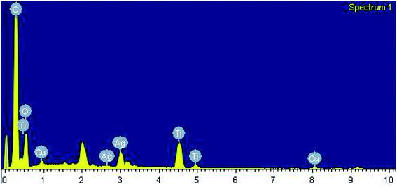
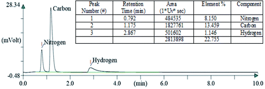
After carrying out the surface analysis, qualitative as well as quantitative analysis was done by means of Energy Dispersive X-ray (EDX), CHN and Inductively Coupled Plasma Atomic Emission Spectroscopy (ICP-AES) analysis. 2.35 wt% Ag and 1.71 wt% Cu were loaded onto TiO2–NGO as indicated by ICP-AES. EDX analysis confirms that the catalyst is composed of C, O, Ti, Ag and Cu, thus indicating the successful grafting of Ag–Cu nanoparticles onto the modified graphene oxide (Fig. 4). The existence of C, N and H in the Cu@Ag–TiO2–NGO was confirmed by CHN analysis, which clearly indicates that N doping was successfully done upto good extent (8.15%) by using dicyandiamide as N precursor (Fig. 5).
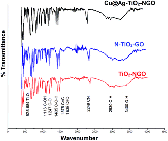
FTIR analysis is one of the most efficient and facile method to examine the chemical composition of the materials in the catalyst. Here, the surface functionality of Cu@Ag–TiO2–NGO, TiO2–NGO and NTiO2–GO was analyzed by FTIR study as shown in Fig. 6. The typical peaks corresponding to functional groups in GO included O–H stretching (3400 cm−1), C–H stretching (2930 cm−1), C![[double bond, length as m-dash]](https://www.rsc.org/images/entities/char_e001.gif) O stretching (1635 cm−1), C
O stretching (1635 cm−1), C![[double bond, length as m-dash]](https://www.rsc.org/images/entities/char_e001.gif) C stretching (1575 cm−1), C–O stretching (1247 cm−1), C–OH stretching (1116 cm−1) and C–O–H bending (1435 cm−1), which confirmed that the oxygen-containing functional groups were successfully incorporated onto NTiO2–GO and TiO2–NGO surface.20 The strong absorption at 536–684 cm−1 is attributed to the stretching vibrations of Ti–O in TiO2.21 The peak corresponding to C
C stretching (1575 cm−1), C–O stretching (1247 cm−1), C–OH stretching (1116 cm−1) and C–O–H bending (1435 cm−1), which confirmed that the oxygen-containing functional groups were successfully incorporated onto NTiO2–GO and TiO2–NGO surface.20 The strong absorption at 536–684 cm−1 is attributed to the stretching vibrations of Ti–O in TiO2.21 The peak corresponding to C![[triple bond, length as m-dash]](https://www.rsc.org/images/entities/char_e002.gif) N bond appeared at 2249 cm−1, while the peak at 1383 cm−1 corresponds to the stretching modes of C
N bond appeared at 2249 cm−1, while the peak at 1383 cm−1 corresponds to the stretching modes of C![[double bond, length as m-dash]](https://www.rsc.org/images/entities/char_e001.gif) N/C–N bonds.22,23 These results demonstrate the successful incorporation of N-containing moieties over the surface of graphene oxide.
N/C–N bonds.22,23 These results demonstrate the successful incorporation of N-containing moieties over the surface of graphene oxide.
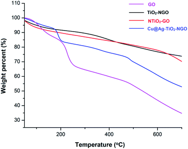
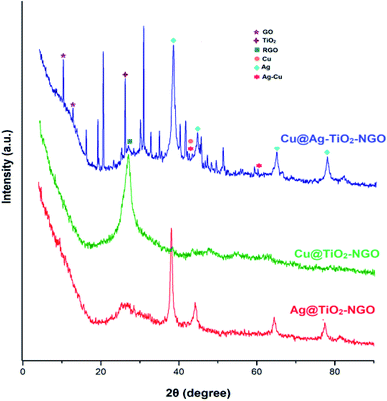
TGA analysis was employed to investigate the thermal stability and degradation process of the catalyst under thermal treatment (Fig. 7). It was remarkably noted that both types of supports (TiO2–NGO and NTiO2–GO) illustrate better thermal stability as compared to GO. However, addition of Ag–Cu nanoparticles lowered the overall thermal stability of the synthesized catalyst. This thermal degradation could be accounted from the catalytic behavior of the nanoparticles which increases the depolymerization as well as reduce the activation energy during thermal process.24–26 The thermo-gram suggests that the initial weight loss observed at the temperature lower than 175 °C which could be attributed to the removal of trapped water molecules between the GO layers. Further, weight loss from 175–205 °C could be assigned to the decomposition of oxygen-containing functional groups from the surface of GO.27 The major weight loss above 470 °C could be due to the combustion of the carbon skeleton of GO.28,29 Hence, from the TGA analysis, it can be inferred that the synthesized catalyst is stable up to 175 °C and further increase in temperature will decompose the catalyst making it ineffective. Fig. 8 represents the XRD of Cu@Ag–TiO2–NGO, Cu@TiO2–NGO and Ag@TiO2–NGO. The incorporation of metallic Ag NPs is confirmed by the diffraction peaks at 38.08, 44.24, 64.50 and 77.51° which were assigned to the face-centered cubic (fcc) planes viz. (111), (200), (220), and (311) of Ag nanoparticles.30 Due to amorphous nature and good dispersion of copper nanoparticles, the distinct peak with less intensity at 2θ = 43.4°corresponds to diffraction from (111) plane of the fcc structure of metallic Cu31 was also observed. In bimetallic Ag–Cu nanoparticles, all the above Ag and Cu diffraction peaks with less intensity were observed, thereby indicating that bimetallic nanoparticles consists of Ag as well as Cu phases. Also, the XRD pattern of Cu@Ag–TiO2–NGO has shown two characteristic peaks corresponding to (220) and (222) planes appearing at 2θ = 42.10 and 60.0°, which confirms the formation of Ag–Cu alloy.32 Also, no oxide peak at 61.7° due to CuO and 37.5° due to Cu2O phase was observed in the bimetallic spectra signifying the oxide free Ag–Cu bimetallic system.33 The characteristic diffraction peak at 2θ = 10.264° correspond to the (002) plane of graphene oxide while the presence of oxygen functionalities in graphene oxide34,35 was confirmed by the appearance of peak at 12.5°. A broad peak at 2θ = 26.75° with a lower intensity corresponds to RGO,36 which may be formed during the catalyst preparation while the intense peak at 2θ = 25.889° corresponds to the (011) plane of TiO2.37 Hence, XRD pattern provides evidence for the co-existence of NGO/TiO2 as well as copper and silver nanoparticles in the nanocomposite.
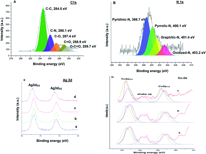
XPS measurements were performed to examine the chemical valence state of Ag–Cu nanoparticles. A survey scan (Fig. 9) revealed the presence of elements C, N, Ag and Cu in the catalysts respectively. The C 1s spectrum (Fig. 9A) could be deconvoluted into five peaks at 284.5 eV, 286.1 eV, 287.4 eV, 288.9 eV and 289.7 eV, which were attributed to C–C, C–N, C–O, C![[double bond, length as m-dash]](https://www.rsc.org/images/entities/char_e001.gif) O and O–C
O and O–C![[double bond, length as m-dash]](https://www.rsc.org/images/entities/char_e001.gif) O bonds respectively.38 The high resolution N 1s spectrum (Fig. 9B) is very useful to explore the different types of nitrogen functionalities in the catalyst. The binding energy centered at 398.7 eV, 400.1 eV, 401.4 eV and 403.2 eV can be assigned to the pyridinic N, pyrrolic N, graphitic N and oxidized N, respectively.39,40 Fig. 9C(a) shows Ag 3d XPS spectra of Ag@TiO2–NGO, where Ag 3d spectra was characterized by doublet peak at 368.2 and 374.1 eV corresponding to Ag 3d5/2 and Ag 3d3/2 respectively, associated with pure Ag nanoparticles.41 Fig. 9C(b) and D(a) shows Ag 3d and Cu 2p core-level spectrum of Cu@Ag–TiO2–NGO, in which Ag 3d binding energy values does not depict much shift as compared to its monometallic counterpart, while the Cu 2p reveals the presence of several peaks with binding energies at 932.4 eV, 952.6 eV, 934.1 eV and 954.8 eV.40
O bonds respectively.38 The high resolution N 1s spectrum (Fig. 9B) is very useful to explore the different types of nitrogen functionalities in the catalyst. The binding energy centered at 398.7 eV, 400.1 eV, 401.4 eV and 403.2 eV can be assigned to the pyridinic N, pyrrolic N, graphitic N and oxidized N, respectively.39,40 Fig. 9C(a) shows Ag 3d XPS spectra of Ag@TiO2–NGO, where Ag 3d spectra was characterized by doublet peak at 368.2 and 374.1 eV corresponding to Ag 3d5/2 and Ag 3d3/2 respectively, associated with pure Ag nanoparticles.41 Fig. 9C(b) and D(a) shows Ag 3d and Cu 2p core-level spectrum of Cu@Ag–TiO2–NGO, in which Ag 3d binding energy values does not depict much shift as compared to its monometallic counterpart, while the Cu 2p reveals the presence of several peaks with binding energies at 932.4 eV, 952.6 eV, 934.1 eV and 954.8 eV.40
The characteristic peak at 932.4 eV and 952.6 eV are attributed to Cu 2p3/2 and Cu 2p1/2 peaks of metallic copper respectively, while the peaks at 934.1 eV and 954.8 eV correspond to Cu 2p3/2 and Cu 2p1/2 peaks of Cu2+ respectively. The presence of Cu2+ was also confirmed by shake-up satellite peak at 941.8 eV, which can be ascribed to the aerial oxidation of Cu atoms present on the surface during sample preparation. Further, to explore the mechanism behind the synergism between Ag–Cu NPs, we have also recorded the XPS spectra of the reused catalysts (after five catalytic runs) in each case and comparative analysis has been carried out. Cu 2p and Ag 3d region of the reused catalyst in case of C–N coupling [Fig. 9C(d) and D(c)] between 4-methoxyaniline and phenyl boronic acid and oxidation [Fig. 9C(c) and D(b)] of 4-chlorobenzyl alcohol were compared with the respective regions of the fresh catalyst [Fig. 9C(b) and D(a)].
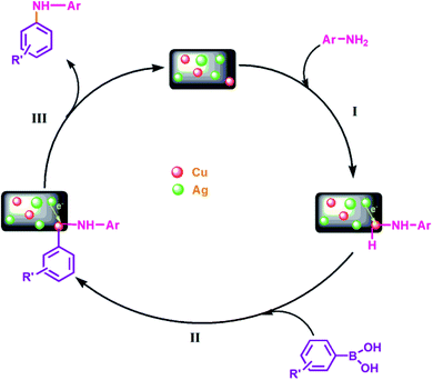
Considering the case of C–N coupling, Fig. 9C(b), C(d), D(a) and D(c) shows the comparative analysis of high resolution Ag 3d and Cu 2p spectra of fresh and reused Cu@Ag–TiO2–NGO. A significant negative shift of the binding energy for Ag 3d (0.4 eV) and Cu 2p (0.2 eV) of reused catalyst relative to that of the fresh catalyst is identified, leading to lower electron density on Ag and higher on Cu, which can be attributed to the electronic synergism between Ag and Cu nanoparticles. Further, a decrease in the intensity of Cu2+ along with an appreciable increase in the intensity of Cu(0) was observed in the reused catalyst which indicates that most of the Cu exist in the metallic form in the reused catalyst. This can be ascribed to the drift of electron density from silver to copper during the reaction, which is actually responsible for the enhanced catalytic activity of the catalyst. This point has been further explained in proposed mechanism part. However, in case of reused catalyst obtained after oxidation, no noticeable change in magnitude as well as intensity of peaks of Ag and Cu was observed. This could possibly be due to the presence of TBHP used as an oxidant and so the synergism existing between Ag and Cu nanoparticles is not clearly visible in terms of binding energy values [Fig. 9C(c) and D(b)]. All these points proved useful in formulating the mechanisms and also help in explaining the existence of interactions existing between Ag and Cu NPs.
Catalytic testing
![[thin space (1/6-em)]](https://www.rsc.org/images/entities/char_2009.gif) :
:![[thin space (1/6-em)]](https://www.rsc.org/images/entities/char_2009.gif) H2O (entries 4 and 5, Table 2), but the promising results were obtained in EtOH using TBHP at 70 °C (entry 7, Table 2). Also, among different oxidants i.e., air, O2, H2O2 and TBHP, the best results were obtained with TBHP in terms of time, yield and selectivity. Hence, to carry out the oxidation reaction, EtOH, TBHP and 70 °C were selected as the optimized solvent, oxidant and temperature respectively. Next, we investigated the scope of the optimized protocol for primary alcohols, secondary alcohols and hydrocarbons.
H2O (entries 4 and 5, Table 2), but the promising results were obtained in EtOH using TBHP at 70 °C (entry 7, Table 2). Also, among different oxidants i.e., air, O2, H2O2 and TBHP, the best results were obtained with TBHP in terms of time, yield and selectivity. Hence, to carry out the oxidation reaction, EtOH, TBHP and 70 °C were selected as the optimized solvent, oxidant and temperature respectively. Next, we investigated the scope of the optimized protocol for primary alcohols, secondary alcohols and hydrocarbons.
| Entry | Catalyst | Time (h) | Yieldb (%) |
|---|---|---|---|
| a Reaction conditions: fluorene (1 mmol), TBHP (1 mmol), catalyst (0.1 g), ethanol (5 mL) at 70 °C.b Column chromatography yield. | |||
| 1 | Ag–Cu@TiO2–NGO | 2 | 72 |
| 2 | Ag@Cu–TiO2–NGO | 2 | 80 |
| 3 | Cu@Ag–TiO2–NGO | 2 | 82 |
| 4 | Cu@TiO2–NGO | 2 | 68 |
| 5 | Ag@TiO2–NGO | 2 | 74 |
| 6 | Ag–Cu@NTiO2–GO | 2 | 65 |
| 7 | Ag@Cu–NTiO2–GO | 2 | 73 |
| 8 | Cu@Ag–NTiO2–GO | 2 | 80 |
| 9 | Cu@NTiO2–GO | 2 | 60 |
| 10 | Ag@NTiO2–GO | 2 | 65 |
| S. no | Solvent | Oxidant | Temperature (°C) | Time (h) | Yieldb (%) |
|---|---|---|---|---|---|
| a Reaction conditions: fluorene (1 mmol), TBHP (1 mmol), Cu@Ag–TiO2–NGO (0.1 g, Cu = 2.69 mol%, Ag = 2.17 mol%), ethanol (5 mL) at 70 °C.b Column chromatography yield. | |||||
| 1 | H2O | Air | 60 | 2 | No reaction |
| 2 | H2O | O2 | 60 | 2 | 40 |
| 3 | H2O | TBHP | 60 | 2 | 60 |
| 4 | EtOH![[thin space (1/6-em)]](https://www.rsc.org/images/entities/char_2009.gif) : :![[thin space (1/6-em)]](https://www.rsc.org/images/entities/char_2009.gif) H2O (3 H2O (3![[thin space (1/6-em)]](https://www.rsc.org/images/entities/char_2009.gif) : :![[thin space (1/6-em)]](https://www.rsc.org/images/entities/char_2009.gif) 1) 1) |
O2 | 60 | 2 | 50 |
| 5 | EtOH![[thin space (1/6-em)]](https://www.rsc.org/images/entities/char_2009.gif) : :![[thin space (1/6-em)]](https://www.rsc.org/images/entities/char_2009.gif) H2O (3 H2O (3![[thin space (1/6-em)]](https://www.rsc.org/images/entities/char_2009.gif) : :![[thin space (1/6-em)]](https://www.rsc.org/images/entities/char_2009.gif) 1) 1) |
TBHP | 60 | 2 | 70 |
| 6 | EtOH | O2 | 80 | 2 | 55 |
| 7 | EtOH | TBHP | 70 | 2 | 82 |
| 8 | EtOH | TBHP | 80 | 2 | 83 |
| 9 | EtOH | TBHP | 60 | 2 | 80 |
| 10 | EtOH | TBHP | 50 | 2 | 75 |
| 11 | CH3CN | TBHP | 60 | 2 | 38 |
| 12 | CH3CN | TBHP | 80 | 2 | 46 |
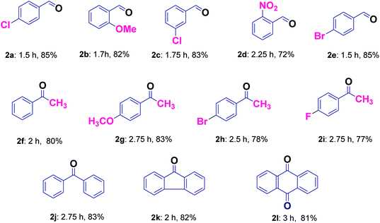
It was found that the reaction with alcohol bearing electron-donating group proceeds smoothly in less time as compared to those containing electron withdrawing group (2b and 2d, Table 3). Good yields without over-oxidized products i.e. carboxylic acids were obtained for the selective oxidation of a variety of primary alcohols (2a–2e, Table 3). The application of this protocol was investigated further for secondary alcohols, which provided good results (2f–2j, Table 3). Hydrocarbons were also found to be oxidized smoothly with good yields (2j–2l, Table 3). Entries 2f and 2j were common products in case of secondary alcohols as well as hydrocarbons (Table 3). Further, in order to evaluate the efficiency of our protocol for the selective liquid-phase oxidation of alcohols and hydrocarbons, the activity of Cu@Ag–TiO2–NGO was compared with some of the reported heterogeneous catalytic systems and the results clearly indicate the supremacy of the synthesized catalyst as compared to other catalysts (Table 4). Also, it was inferred that Ag/TiO2 and Cu/TiO2 (without graphene) exhibit low catalytic activity as compared to Cu@Ag–TiO2–NGO indicating that TiO2–NGO plays a prominent role as a composite material in stabilizing the metal NPs owing to its high surface area and thermal stability.
| Catalyst | Reaction conditions | Time | Yield (%) | Reference |
|---|---|---|---|---|
| STA-12(Co) | 4-Chlorobenzyl alcohol, TBHP, ethylacetate, 60 °C | 3h | 58 | 42 |
| Ag–ZnO nanocomposite | 4-Chlorobenzyl alcohol, TBHP, acetonitrile, 80 °C | 5 min | 90 | 43 |
| [Cu2(μ-O2CC6H5)4(4-Etpy)2] | 4-Chlorobenzyl alcohol, TBHP, methanol, 65 °C | 5 h | 78 | 44 |
| [Cu2(μ-O2CC6H5)4(4-DMAP)2] | 4-Chlorobenzyl alcohol, TBHP, methanol, 65 °C | 5 h | 75 | 44 |
| Cu/TiO2 | 4-Chlorobenzyl alcohol, TBHP, EtOH, 70 °C | 1.5 h | 57 | This work |
| Ag/TiO2 | 4-Chlorobenzyl alcohol, TBHP, EtOH, 70 °C | 1.5 h | 62 | This work |
| Au/TiO2 | Benzyl alcohol, TBHP, solvent free, 94 °C | 2 h | 50 | 45 |
| LaCrO3 | 4-Chlorobenzyl alcohol, TBHP, solvent-free, 90 °C | 2.5 h | 81 | 46 |
| Pd-G/SBA-16 G | Benzyl alcohol, air, toluene, 100 °C, K2CO3 | 7 h | 99 | 47 |
| Pt@CHs | Benzyl alcohol, O2, toluene, 80 °C, KOH | 3 h | 99 | 48 |
| Modified graphene based AgCu(0) bimetallic catalyst (Cu@Ag–TiO2–NGO) | 4–Chlorobenzyl alcohol, TBHP, EtOH, 70 °C | 1.5 h | 85 | This work |
C–N bond formation
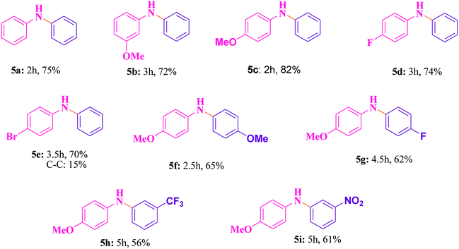
The best catalyst i.e. Cu@Ag–TiO2–NGO which we obtained during the optimization in case of oxidations was chosen to perform C–N cross-coupling reaction. In this work, we initially selected the coupling reaction of phenyl boronic acid with aniline in the absence of base as the model reaction to optimize the reaction parameters and good results were obtained as the N in the catalyst imparts basic character, thereby avoiding the use of additional base in the reaction. The test reaction was optimized by using different solvents (H2O, EtOH, CH3CN and DMF) and H2O was found to be the best, whereas others were proved to be significantly less effective (Table 5). The test reaction was performed using 0.1 g of the Cu@Ag–TiO2–NGO in the absence of base using H2O as a solvent at 80 °C. To explore the scope and generality of aryl C–N bond formation, both electron-donating and electron-withdrawing substituted aromatic amines were tested under the optimized reaction conditions and it has been found that substrates containing electron-withdrawing groups (F and Br) at the para-position of the amines undergo coupling smoothly with phenylboronic acid to give the corresponding N-arylated products with improved yields (5d and 5e, Table 6). Further, promising results were obtained with 4-fluoroaniline, but no product was obtained with 2-fluoroaniline. In case of C–N coupling between 4-bromoaniline and phenyl boronic acid (5e, Table 6), small amount of C–C coupled product as the side reaction was also observed. The desired N-arylation product was obtained in good yield with 4-methoxyaniline as compared to 3-methoxyaniline (5b and 5c, Table 6). However, no product formation was observed with 2-methoxyaniline even after a long time. Hence, it was inferred that reaction of para- or meta-substituted anilines gave good yield as compared to ortho-substituted anilines, which were found to be less reactive due to steric hindrance. Indoles and aliphatic amines undergo coupling very slowly and the corresponding products could not be isolated. C–N coupling was also explored using a variety of p- or m-substituted arylboronic acids under the optimal reaction conditions and moderate results were obtained (5f–5i, Table 6).| S. no. | Solvent | Temperature (°C) | Time (h) | Yieldb (%) |
|---|---|---|---|---|
| a Reaction conditions: aniline (1 mmol), phenylboronic acid (1 mmol), Cu@Ag–TiO2–NGO (0.1 g) in H2O (5 mL).b Column chromatography yield. | ||||
| 1 | Water | RT | 8 | 25 |
| 2 | Water | 80 | 3 | 75 |
| 3 | Water | 100 | 3.75 | 76 |
| 4 | Acetonitrile | RT | 6.5 | 35 |
| 5 | Toluene | RT | 6 | 35 |
| 6 | Ethanol | 70 | 5.5 | 55 |
| 7 | Methanol | RT | 6 | 35 |
| 8 | H2O/EtOH (1![[thin space (1/6-em)]](https://www.rsc.org/images/entities/char_2009.gif) : :![[thin space (1/6-em)]](https://www.rsc.org/images/entities/char_2009.gif) 1) 1) |
RT | 5 | 35 |
| 9 | H2O/EtOH (1![[thin space (1/6-em)]](https://www.rsc.org/images/entities/char_2009.gif) : :![[thin space (1/6-em)]](https://www.rsc.org/images/entities/char_2009.gif) 1) 1) |
60 | 5 | 53 |
| 10 | H2O/EtOH (1![[thin space (1/6-em)]](https://www.rsc.org/images/entities/char_2009.gif) : :![[thin space (1/6-em)]](https://www.rsc.org/images/entities/char_2009.gif) 1) 1) |
70 | 5 | 64 |
Proposed mechanisms
Oxidations
To gain an insight into the reaction mechanism of the oxidation of alcohols and hydrocarbons, and to discover if the radical process is involved in the catalytic reaction, a radical-trapping experiment using TEMPO, a radical scavenger was performed. The reaction in case of 2a, Table 3 was performed first for 40 min and the product was obtained with 50% yield. To this reaction mixture, TEMPO (1 mmol) was added and the reaction was further carried out for 90 min (completion time without TEMPO). No significant conversion was observed, which clearly indicates that the oxidation reaction occurred via radical intermediates. Moreover, the comparative XPS spectra of the fresh and reused Cu@Ag–TiO2–NGO does not provided direct evidence of the intense electronic interactions between Ag and Cu nanoparticles but the enhanced catalytic activity of the catalyst convinced us that some sort of electronic interactions between Ag and Cu nanoparticles as observed in C–N coupling also occurs during oxidation but due to the presence of TBHP not much change was observed in binding energy values. Hence, benefiting from the enhanced bimetallic synergistic effect, a plausible radical mechanism involving the synergistic effect of Ag and Cu nanoparticles and modified graphene support was proposed (Fig. 11).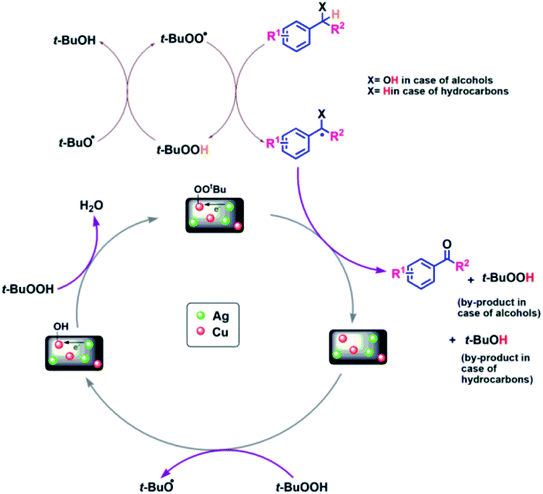 | ||
| Fig. 11 Probable mechanistic path for Cu@Ag–TiO2–NGO catalyzed oxidation of alcohols and hydrocarbons. | ||
Recyclability
For a heterogeneous catalyst, the recyclability is an imperative aspect to be studied. To address this issue, the reusability of Cu@Ag–TiO2–NGO was investigated for oxidation reaction (2a, Table 3) under the optimal conditions. The catalyst was recovered by filtration from the reaction mixture after the completion of the reaction, washed consecutively with ethyl acetate (3 × 10 mL), deionized water, dried and used for the next run. It was found that there was no evident decline in its catalytic activity even after five runs, which clearly shows that catalyst is highly stable under the reaction conditions and can be used for more than five runs. Similarly, the recyclability of the catalyst was tested for Chan–Lam coupling reaction (5c, Table 6) and it was found that, Cu@Ag–TiO2–NGO can be recycled five times with minimal loss of activity (Fig. 12).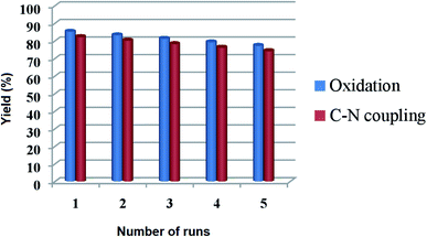 | ||
| Fig. 12 Recyclability of Cu@Ag–TiO2–NGO for oxidation (2a, Table 3) and Chan–Lam coupling reaction (5c, Table 6) under optimized reaction conditions. | ||
Conclusions
In summary, two different support materials i.e. TiO2–NGO and NTiO2–GO were prepared using simple methodology and then characterized by surface area analysis, which indicates that TiO2–NGO has larger specific surface area. Using both types of supports, ten different catalyst based on Ag and Cu were synthesized and their catalytic activity was further compared, out of which Cu@Ag–TiO2–NGO exhibited significantly higher catalytic activity for the oxidation of alcohols and hydrocarbons as well as Chan–Lam coupling reactions compared to other prepared catalysts. This enhanced performance of the synthesized catalyst could be due to the presence of nitrogen functionalities in the GO and the electronic synergism between Ag and Cu metal nanoparticles as depicted by XPS. This high efficiency of Cu@Ag–TiO2–NGO which was ascribed to the synergistic effect of the two metals was explained well by proposed mechanism. More importantly, our strategy provides the rational design of Ag–Cu bimetallic NPs with good dispersion for a broader range of applications in the future.Conflicts of interest
There are no conflicts to declare.Acknowledgements
We thank the Head, ACMS, IIT Kanpur for XPS study; Head, SAIF, IIT Bombay for ICP-AES, HR-TEM and CHN studies; AMRC, IIT Mandi for SEM, EDX, FT-IR and PXRD studies; and Department of Chemistry, University of Jammu for BET, FTIR and TGA. Financial assistance from the Department of Science & Technology under PURSE programme; UGC New Delhi under SAP; and to authors N. S., A. C. (RUSA-2.0), M. K. (SRF, CSIR) and C. S. (SRF, UGC) is gratefully acknowledged.References
- V. B. Mohan, K. Lau, D. Hui and D. Bhattacharyya, Composites, Part B, 2018, 142, 200–220 CrossRef CAS.
- X. Huang, X. Qi, F. Boey and H. Zhang, Chem. Soc. Rev., 2012, 41, 666–686 RSC.
- Z. Lin, G. Waller, Y. Liu, M. Liu and C. P. Wong, Adv. Energy Mater., 2012, 2, 884–888 CrossRef CAS.
- B. Xiong, Y. Zhou, Y. Zhao, J. Wang, X. Chen, R. O. Hayre and Z. Shao, Carbon, 2013, 52, 181–192 CrossRef CAS.
- Q. Zhang, Q. An, X. Luan, H. Huang, X. Li, Z. Meng, W. Tong, X. Chen, P. K. Chu and Y. Zhang, Nanoscale, 2015, 7, 14002–14009 RSC.
- X. Liu, H. Zhang, Y. Ma, X. Wu, L. Meng, Y. Guo, G. Yu and Y. Liu, J. Mater. Chem. A, 2013, 1, 1875–1884 RSC.
- D. Chen, H. Feng and J. Li, Chem. Rev., 2012, 112, 6027–6053 CrossRef CAS PubMed.
- P. Kundu, C. Nethravathi, P. A. Deshpande, M. Rajamathi, G. Madras and N. Ravishankar, Chem. Mater., 2011, 23, 2772–2780 CrossRef CAS.
- H. M. Jeong, J. W. Lee, W. H. Shin, Y. J. Choi, H. J. Shin, J. K. Kang and J. W. Choi, Nano Lett., 2011, 11, 2472–2477 CrossRef CAS PubMed.
- A. L. M. Reddy, A. Srivastava, S. R. Gowda, H. Gullapalli, M. Dubey and P. M. Ajayan, ACS Nano, 2010, 4, 6337–6342 CrossRef CAS PubMed.
- L. S. Zhang, X. Q. Liang, W. G. Song and Z. Y. Wu, Phys. Chem. Chem. Phys., 2010, 12, 12055–12059 RSC.
- L. Qu, Y. Liu, J. B. Baek and L. Dai, ACS Nano, 2010, 4, 1321–1326 CrossRef CAS PubMed.
- S. Yang, L. Zhi, K. Tang, X. Feng, J. Maier and K. Mullen, Adv. Funct. Mater., 2012, 22, 3634–3640 CrossRef CAS.
- X. Duan, Z. Ao, H. Sun, S. Indrawirawan, Y. Wang, J. Kang, F. Liang, Z. H. Zhu and S. Wang, ACS Appl. Mater. Interfaces, 2015, 7, 4169–4178 CrossRef CAS PubMed.
- J. H. Park, S. Kim and A. J. Bard, Nano Lett., 2006, 6, 24–28 CrossRef CAS PubMed.
- M. Ksibi, S. Rossignol, J. M. Tatibouet and C. Trapalis, Mater. Lett., 2008, 62, 4204–4206 CrossRef CAS.
- Y. W. Cheng, R. C. Y. Chan and P. K. Wong, Water Res., 2007, 41, 842–852 CrossRef CAS PubMed.
- G. Darabdhara, M. A. Amin, G. A. M Mersal, E. M. Ahmed, M. R. Das, M. B. Zakaria, V. Malgras, S. M. Alshehri, Y. Yamauchi, S. Szunerits and R. Boukherroub, J. Mater. Chem. A, 2015, 3, 20254–20266 RSC.
- W. L. Zhang and H. J. Choi, Chem. Commun., 2011, 47, 12286–12288 RSC.
- M. Hu, Z. Yao and X. Wang, AIMS Mater. Sci., 2017, 4, 755–788 Search PubMed.
- M. Nasrollahzadeh, M. Atarod, B. Jaleh and M. Gandomirouzbahani, Ceram. Int., 2016, 42, 8587–8596 CrossRef CAS.
- L. Wang, C. Wan, Y. Fu, H. Chen, X. Liu and M. Li, J. Electron. Mater., 2014, 43, 132–136 CrossRef CAS.
- H. Miao, S. Li, Z. Wang, S. Sun, M. Kuang, Z. Liu and J. Yuan, Int. J. Hydrogen Energy, 2017, 42, 28298–28308 CrossRef CAS.
- S. B. Khan, F. Ali, T. Kamal, Y. Anwar, A. M. Asiri and J. Seo, Int. J. Biol. Macromol., 2016, 88, 113–119 CrossRef CAS PubMed.
- S. B. Khan, K. A. Alamry, E. N. Bifari, A. M. Asiri, M. Yasir, L. Gzara and R. Z. Ahmad, J. Ind. Eng. Chem., 2015, 24, 266–275 CrossRef CAS.
- D. Kim, M. Jang, J. Seo, K. H. Nam, H. Han and S. B. Khan, Compos. Sci. Technol., 2013, 75, 84–92 CrossRef CAS.
- G. Wang, Z. Yang, X. Li and C. Li, Carbon, 2005, 43, 2564–2570 CrossRef CAS.
- P. Liu, K. Gong, P. Xiao and M. Xiao, J. Mater. Chem., 2000, 10, 933–935 RSC.
- W. L. Zhang, B. J. Park and H. J. Choi, Chem. Commun., 2010, 46, 5596–5598 RSC.
- L. Liu, J. Liu, Y. Wang, X. Yan and D. D. Sun, New J. Chem., 2011, 35, 1418–1423 RSC.
- Z. Chang, S. Huo, W. Zhang, J. Fang and H. Wang, J. Phys. Chem. C, 2017, 121, 11368–11379 CrossRef CAS.
- X. Liu, A. Wang, X. Wang, C.-Y. Mou and T. Zhang, Chem. Commun., 2008, 44, 3187–3189 RSC.
- M. Valodkar, P. S. Rathore, R. N. Jadeja, M. Thounaojam, R. V. Devkar and S. Thakore, J. Hazard. Mater., 2012, 201–202, 244–249 CrossRef CAS PubMed.
- W. Wang, C. Bai and L. Zhang, Catal. Commun., 2019, 125, 1–5 CrossRef.
- S. Rana, S. Maddila and S. B. Jonnalagadda, Catal. Sci. Technol., 2015, 5, 3235–3241 RSC.
- N. Pramanik, J. De, R. K. Basu, T. Rath and P. P. Kundu, RSC Adv., 2016, 6, 46116–46133 RSC.
- Y. Zhang, X. Zhang, H. Huang, J. Cai, B. Huang and S. Lin, New J. Chem., 2018, 42, 19755–19763 RSC.
- Y. Tian, F. Wang, Y. Liu, F. Pang and X. Zhang, Electrochim. Acta, 2014, 146, 646–653 CrossRef CAS.
- C. Sharma, M. Kaur, A. Choudhary, S. Sharma and S. Paul, Catal. Lett., 2019, 150, 82–94 CrossRef.
- L. G. Bulusheva, A. V. Okotrub, Y. V. Fedoseeva, A. G. Kurenya, I. P. Asanov, O. Y. Vilkov, A. A. Koos and N. Grobert, Phys. Chem. Chem. Phys., 2015, 17, 23741–23747 RSC.
- G. Darabdhara, B. Sharma, M. R. Das, R. Boukherroub and S. Szunerits, Sens. Actuators, B, 2017, 238, 842–851 CrossRef CAS.
- A. Farrokhi, M. Jafarpour and R. Najafzade, Catal. Lett., 2017, 147, 1714–1721 CrossRef CAS.
- A. F. Shojaei, K. Tabatabaeian, M. A. Zanjanchi, H. F. Moafi and N. Modirpanah, J. Chem. Sci., 2015, 127, 481–491 CrossRef CAS.
- P. Sarmah, B. K. Das and P. Phukan, Catal. Commun., 2010, 11, 932–935 CrossRef CAS.
- V. R. Choudhary, D. K. Dumbre and S. K. Bhargava, Ind. Eng. Chem. Res., 2009, 48, 9471–9478 CrossRef CAS.
- S. J. Singh and R. V. Jayaram, Synth. Commun., 2012, 42, 299–308 CrossRef CAS.
- H. Yang, X. Han, Z. Ma, R. Wang, J. Liu and X. Ji, Green Chem., 2010, 12, 441–451 RSC.
- H. Goksu, H. Burhan, S. D. Mustafov and F. Sen, Sci. Rep., 2020, 10, 5439 CrossRef CAS PubMed.
Footnote |
| † Electronic supplementary information (ESI) available. See DOI: 10.1039/d0ra01540g |
| This journal is © The Royal Society of Chemistry 2020 |

