 Open Access Article
Fabrication of a ceramic/metal (Al2O3/Al) composite by 3D printing as an advanced refractory with enhanced electrical conductivity
Rat Prathumwan and
Kittitat Subannajui *
*
Faculty of Science, Mahidol University, 272 Rama VI Road, Ratchathewi District, Bangkok 10400, Thailand. E-mail: kittitat.sub@mahidol.ac.th
First published on 1st September 2020
Abstract
Fused deposition modelling (3D) printing is used extensively in modern fabrication processes. Although the technique was designed for polymer printing, it can now be applied in advanced ceramic research. An alumina/aluminum (Al2O3/Al) composite refractory can be fabricated by mixing metallic aluminum in a polymer to form an Al/polymer composite filament. The filament can be printed via a regular thermoplastic material extrusion printer with no machine modification. In this study, Al/polymer composite samples were printed in a crucible shape and sintered at different temperatures to form Al2O3/Al composite refractory specimens. The sintered samples were examined via several analytical techniques such as scanning electron microscopy, energy dispersive X-ray spectroscopy, X-ray diffraction, compressive testing, hardness testing, XPS, and Hall measurement. Unlike other ceramic printing techniques that require expensive 3D printing machines and a very high temperature furnace (above 1500 °C) for post processing, this study demonstrates the viability of fabricating refractory items using a cost-effective fused deposition modelling 3D printer and a low temperature furnace (900 °C). The samples did not disintegrate at 1400 °C and were still sufficiently electrically conductive for advanced refractory applications.
Introduction
Over the last decade, additive manufacturing has seen extraordinary developments that have led to its commercial adoption worldwide. Three-dimensional (3D) printing, a subset of additive manufacturing, has seemingly limitless applications such as biomedical applications that involve making models for medical education, such as artificial cranial elements, artificial fingers, heart valves, and cell-printing.1–6 The applications have also been expanded to sensors, food, injection molds, metal casting, batteries, actuators, nanomaterials, building materials, and robotic parts.7–12 Continuous research on 3D printing is necessary to accommodate future application ideas. There are numerous types of 3D printing techniques such as stereolithography, selective laser sintering (SLS) or selective laser melting (SLM), ram extrusion printing, and gel jet printing.13–16 Compared to other techniques, Fused Deposition Modelling 3D printing (FDM) is the most widely used 3D printing technique due to its low investment cost and easy access.17 The material for FDM printing is typically a polymer, though metallic samples can be obtained via a lost wax post processing method if required. However, ceramics are not a common material for FDM. Printing ceramics is not a simple task in additive manufacturing. Most ceramic printing technologies are expensive and complicated in terms of the equipment.18–20 For example, in order to print ceramics with SLS, a high power laser is required, and the price of the machine is relatively high.21 For the paste extrusion technique, the ceramic paste is extruded by a ram that provides a lower resolution than that of typical FDM systems with a more complicated setup.22,23 Even an inkjet technique that uses a jet valve to print liquid polymer on ceramic particles is both expensive and complicated.24However, this study demonstrates that ceramics can be printed using a typical FDM machine. The technique is much simpler than competing ceramic additive manufacturing techniques since it does not rely on expensive 3D printer systems or require a complicated setup.25 In this study, a refractory alumina/aluminum (Al2O3/Al) composite item was fabricated using a regular FDM printer. Although Al2O3 is well known and thoroughly researched, the refractory properties of the Al2O3/Al composite have not been extensively studied. For Al2O3 fabrication, the usual sintering temperature of alumina must be above 1400 °C, which requires high energy consumption and is a wasteful process.26,27 This is not unexpected because Al2O3 has a very high melting point (2072 °C), and the atomic movement to fill the particle gaps is very limited at low temperature.28,29 Being a high temperature process, the energy consumption is very high and the instrumentation, such as a high-temperature furnace, is expensive. An Al2O3/Al composite can avoid such issues as it requires a much lower sintering temperature to produce a material that is capable of surviving as a refractory at high temperatures. The technique developed in this study allows anyone to fabricate a refractory with an inexpensive and simple FDM machine at a low temperature.
Material and methods
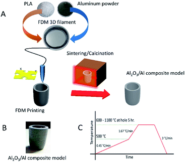
The fabrication of the Al2O3/Al composite in this work started by blending polylactic acid (polylactic acid (PLA), Ingeo™ biopolymer 3251D, NatureWorks Asia Pacific) with Al powder (aluminum powder with 10 μm average size and 99+% purity, SkySpring Nanomaterials, Inc.) with a composition of 70% Al by weight. As shown in Fig. 1A, the blended composite was formed into a filament with a diameter of 1.75 mm by an extruder machine. This filament had a very high Al loading content but was still printable by the FDM printer. The samples were formed having a crucible shape. The crucibles were placed in a furnace to eliminate the binder and to sinter the particles. The debinding process allows the PLA to completely decompose, thus permitting Al atoms to diffuse so as to bond the particles to each other in the succeeding sintering process. Because the melting temperature of Al is only 660 °C, the diffusion of Al within the Al particles was much faster than that within Al2O3. Therefore, the sintering of Al particles could also be accomplished at much lower temperature as well. At a higher temperature, the surface of the Al particles was oxidized and a refractory Al/Al2O3 core/shell structure was formed. The formation mechanism initiated on the particle surface is possible due to the high surface per volume ratio of the particles. Fig. 1B shows the Al2O3/Al crucible sample. The initial color of the Al particles and the as-printed Al/PLA blended samples was black but the sample turned a white-grey color after the sintering process that formed the final Al2O3/Al composite material. As shown in Fig. 1C, the temperature profile of the sintering process implied that a low heating rate (0.4 °C min−1) was critical to obtain any desired 3D shape because a high heating rate might destroy the original printed structure. After the sintering process, the Al2O3/Al composite can function as a refractory. The composite Al2O3/Al could withstand temperatures above the melting temperature of Al (660 °C) without molten Al metal loss because the Al2O3/Al shell encapsulated Al within each particle and endured the elevated temperatures.Results and discussion
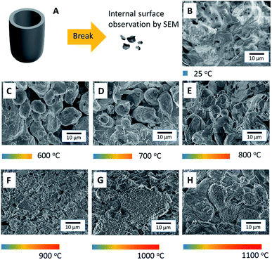
Differential scanning calorimetry (DSC) and thermal gravimetric analysis (TGA) of PLA were performed at a heating rate of 2 °C min−1, and indicated that the glass transition temperature of PLA was 65 °C, as shown in Fig. 2A. The melting point and decomposition temperature of PLA was found to be 175 °C and 365 °C, respectively. Thus, the PLA filament could be printed via FDM 3D printing at temperatures in the range of 175–365 °C. Above this temperature range, the polymer was entirely burned away. In Fig. 2B, DSC and TGA show that the melting point of Al particles is at 660 °C. The particles were oxidized during heating and were oxidized even more at temperatures above 800 °C. The mass of Al particles had increased due to the incorporation of oxygen atoms during the oxidation process. The DSC and TGA curves of the as-printed PLA/Al composite are shown in Fig. 2C. The results are similar to the combination between the results from the PLA and Al particles. The glass transition temperature of PLA appeared at 65 °C, the melting point of PLA occurred at 175 °C, and the decomposition temperature was determined to be 375 °C. Above this point, the polymer was decomposed. The results also suggest that sintering above 800 °C could enhance the oxidation on the surface of the Al particles.Although DSC and TGA sufficiently analyzed the phase transformation in the composite, the sintering mechanism of the Al particles could not be satisfactorily elucidated by their application. Hence, scanning electron microscopy (SEM) was conducted to observe the sintering of the particles in the printed samples. The schematic in Fig. 3A shows the process for breaking the samples into small pieces in order to observe their internal structure. The SEM image of the as-printed internal structure of the Al/polymer composite in Fig. 3B shows the continuous bulk structure of the PLA polymer that completely surrounds the Al particles. Fig. 3C shows the printed sample after being sintered at 600 °C; only the Al particles were left with no remnant traces of the polymer material. The Al particles in the sample were only slightly fused to each other and the structure still contained a significant volume of cavities. When the sample was sintered at 700 °C, as shown in Fig. 3D, the interparticle fusion improved. In Fig. 3E, at the sintering temperature of 800 °C, most particles were sintered together and the porosity was much lesser than that at lower sintering temperatures. As shown in Fig. 3F, the particles sintered at 900 °C demonstrated even greater fusion with each other. At this point, even the shape of the particles had started to reform. Above 1000 °C, as shown in Fig. 3G and H, the structures were totally reformed. Almost none of the cavities were observed in the sample with a sintering temperature of 1100 °C. Unlike the typical sintering of the Al2O3 refractory, the result showed that an extremely high sintering temperature is not required in this work and that a temperature of 900 °C or above is sufficient to sinter the particles to each other.
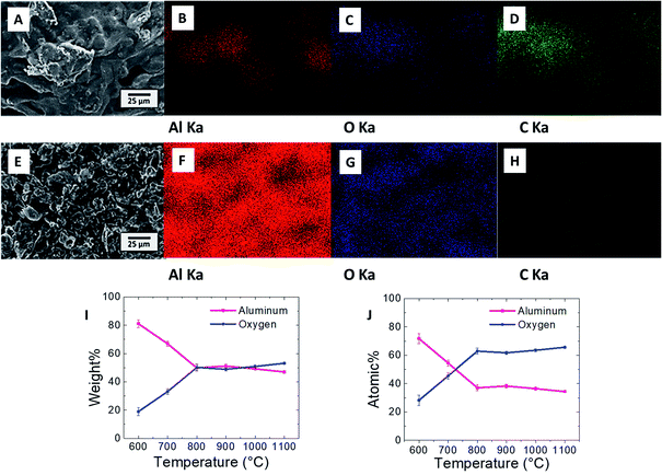
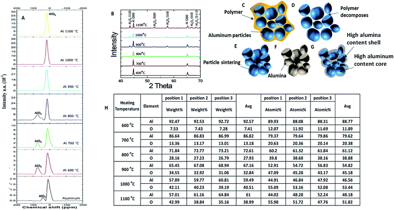
Fig. 4A shows the SEM image of the Al/polymer composite structure of an FDM printed sample before the sintering process. Energy dispersive X-ray (EDS) mappings of aluminum, oxygen, and carbon (Al, O, and C) from the same area as Fig. 4A are shown in Fig. 4B, C, and D, respectively. The EDS signals appear in the same geometric area because PLA and the Al particles were mixed homogeneously. The carbon and oxygen signals can be attributed to the PLA functional groups and the Al signal can be attributed to the Al particles, which were mixed inside the composite. The SEM image of the 900 °C sintered structure is shown in Fig. 4E and the EDS mappings of Al, O, and C are shown in Fig. 4F, G, and H, respectively. The Al and O signal appeared across the structure according to the geometry, with only Al and Al2O3 being left in the sample. After sintering, the polymer completely was decomposed, as evidenced by the absence of the EDS signal for C. The average mass that was measured by EDS is shown in Fig. 4I. The weight ratio of Al decreased and the weight ratio of O increased drastically until 800 °C. When the outer shell of the particles had been significantly oxidized, most of the X-ray signal came from the Al2O3 shell, which could be hardly oxidized further. This meant that the oxygen content could only increase slightly at temperatures above 800 °C because X-rays penetrated poorly deep into the Al core. The results from the EDS analysis of atomic ratios in Fig. 4J suggests that this is the same mechanism wherein oxidation was slower when the sintering temperature was increased above 800 °C. Although the O signal increased when the temperature was raised, it was difficult to totally oxidize the Al particles to the core at 900 °C. This oxidation condition can be observed in detail in Fig. 5A where the 3D printed samples under different sintering conditions were measured by Solid State Nuclear Magnetic Resonance (SS-NMR). For the SS-NMR result of pure aluminum, the oxidation peaks appeared to be AlO5 and AlO6, and the signal is weak. This oxidation state changed to AlO4 and AlO6 with a stronger oxidation signal at higher sintering temperatures in the range of 600–800 °C. At 900 °C, the oxidation peak appeared to be only for AlO6, and the intensity of AlO6 at 1100 °C is more than 10 times higher than the intensity of AlO6 of pure aluminum without the sintering process, which means that the oxidation of the 3D printed green aluminum sample was severely oxidized after the sintering process and the atomic structure of pure aluminum changed to the alumina structure.
The XRD spectrum at different sintering temperatures is shown in Fig. 5B. The peaks of Al appeared in the samples at every sintering temperature. At a sintering temperature of 900 °C, the peaks of Al2O3 emerged, and became more prominent at higher sintering temperatures. This valuable information confirmed that the sintering temperature must be at least 900 °C to form the Al2O3 shell.
From the results above, the formation mechanism of Al2O3/Al could be summarized in Fig. 5C–G. The composite filament was printed out in a crucible shape and the Al particles were mixed inside the polymer, as shown in Fig. 5C. The Al particles were dispersed close to each other due to a high Al loading content. PLA acted as a polymeric binder between the Al particles, which allowed the Al particles to adhere together and flow through the 3D printing nozzle. In Fig. 5D, the polymeric binder disappeared due to decomposition at 365 °C, which was confirmed by DSC and TGA analyses. The particles remained close together with a very low strength in the absence of a proper binder. This temperature was critical since the structure could be deformed or cracked if the heating rate was too high. Because external force could break the sample once the binder is decomposed, all sintering FDMs must be executed inside the same furnace to minimize the sample movement. As shown in Fig. 5E, the Al atoms diffused between the particles at high sintering temperatures, forming junctions at 900 °C. The strength of the sample increased and the sample could be handled outside the furnace; however, during the sintering process, the particles were also calcined and the surfaces were oxidized. The outer surfaces of the Al particles were oxidized into the Al2O3 shells, as shown in Fig. 5F, but the Al cores were still not fully oxidized (Fig. 5G). Both Al2O3 and Al were partially connected between the particles. The fact that the printed samples in this work could endure temperatures above 1100 °C while normal Al samples should be molten at 660 °C was a strong proof that the printed samples could be used as refractory materials. The concept of partial oxidation was proved by Fig. 5H, which shows the table of EDS results of different positions at different sintering temperatures. It was obvious that the oxygen to aluminum ratio was higher at the surface compared with the inner core. This was because oxygen can oxidize the aluminum surface easier than penetrating it to oxidize the core. The lower sintering temperatures provided lower oxidation with lower oxygen to aluminum ratios in all the areas. At a higher temperature, oxygen can penetrate deeper, which can be implied from the oxygen to aluminum ratios at deeper position. The aluminum ratio at the core was still higher than the expected ratio of Al2O3, in which the aluminum to oxygen ratio should be 2/3. This result can be used to deduce that the assumption of partial oxidation at the core was reasonable; however the core and shell did not have a sharp transition but rather a gradient transition between the highly oxidized area and the less oxidized area. Partial oxidation leads to many other effects such as the semi-conduction of Al2O3/Al composites.
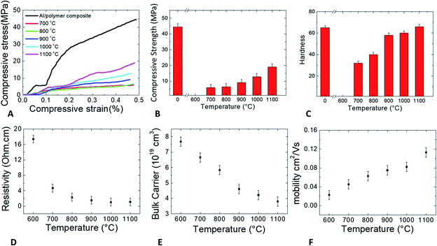
Fig. 6A shows the compressive stress tests of the FDM printed samples. The as-printed Al/polymer composite had the highest strength than that of the other samples, which had ceramic scaffolds. The stress increased linearly at the beginning of the as-printed Al/polymer stress–strain curve and became constant with the increase in strain for a certain period thereafter. After the strain reached 0.1%, the stress rose again and increased until the sample broke at 44 MPa stress and 0.48% strain. The stress–strain characteristics of the Al2O3/Al composites, however, were not linear, and the maximum strains of the composites were in the range of 0.44–0.48%, indicating that the Al2O3/Al composites were brittle. As seen in Fig. 6B, the strength of the Al/polymer composite was much higher than that of Al2O3/Al composites, implying that the polymer binder was stronger than the ceramic interconnection between the particles. The strength of the sample at the sintering temperature of 600 °C was not reported because the sample immediately broke after the compressive test started. The sudden breakdown occurred because the sintering temperature of 600 °C was not sufficient to form proper interconnections between the particles, making the sample too weak for compressive testing. The strengths of other Al2O3/Al composites increased exponentially with higher sintering temperatures. A higher sintering temperature promotes better Al diffusion, which can strengthen the interconnection between the particles. As shown in Fig. 6C, the hardness of the sample at the sintering temperature of 600 °C was also not reported since the sample was destroyed before the hardness was properly tested. These effects confirm that a sintering temperature of 600 °C is not suitable for Al2O3/Al composite fabrication. The hardness of the surface was greatly improved in the samples with sintering temperatures above 800 °C due to the faster Al diffusion rates between the particles. When the sintering temperature approached 1100 °C, the hardness of the Al/polymer and the Al2O3/Al composite was almost equal. From the compressive stress and hardness tests, the optimum sintering temperature of the Al2O3/Al composite was determined to be 900 °C or above in order to ensure that the composite could behave like a refractory with proper strength and hardness.
As shown in Fig. 6D, the resistivity of the Al2O3/Al composite was analyzed by 4-point probe measurement. The resistivity of the sample with a sintering temperature of 600 °C was high, which implied that the particles were not well connected and electrical current could not be easily conducted through the particles in the sample. For the samples with higher sintering temperatures, the resistivity exponentially decreased and the electrical conductivity increased. At higher temperatures, the Al atoms diffused and bonded between the interconnecting particles, thus increasing the electrical conductivities. The resistivity was lowered to the saturation value of 1 ohm cm in the samples with sintering temperatures in the range of 1000–1100 °C. The measured value was higher than the Al resistivity but lower than the Al2O3 resistivity,30,31 which is strong proof that the Al2O3/Al composite was still a conductor. The high temperature did not completely oxidize the Al particles to the core because if the Al particles had been totally calcined, the resistivity of the samples would be very high due to the dominance of non-electrically conductive Al2O3. In this work, the samples were still partially conductive after the high temperature sintering process.
The bulk carrier concentration and electron mobility were determined by Hall measurement and are shown in Fig. 6E and F, respectively. Both the terms are closely related to the oxidation and interconnection of the particles in the sintered samples. The carrier concentration depended mainly on the remnant amount of Al phase in the composite because Al has a high carrier concentration while Al2O3 has a significantly lower carrier concentration. Carrier mobility governs the ability of the electrons to move inside the composite sample, which relies on the quality of interconnection after sintering. Without Al diffusion to form the interconnection during the sintering process, the carrier mobility cannot increase. In this work, the carrier concentration gradually decreased, which indicated that Al continued to be oxidized with increasing temperature. The electron mobility in the samples, however, increased with higher sintering temperatures, which suggests that increasing the temperature increased the diffusion of Al atoms to interconnect the particles.
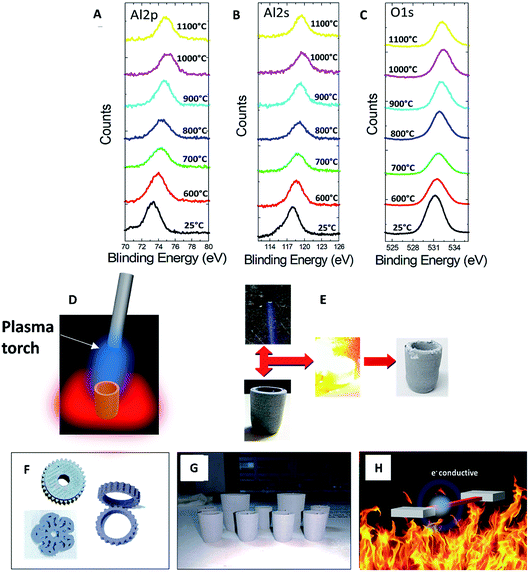
Fig. 7A, B, and C are the X-ray photoelectron spectroscopy (XPS) spectra of Al 2p, Al 2s, and O 1s, respectively. The center of the Al 2p peak was at 73.6 eV in the sample with a sintering temperature of 600 °C. When the sintering temperatures increased, the binding energy shifted to higher energies, causing the center of the Al 2p peak to shift to 75.1 eV in the sample with a sintering temperature of 1100 °C. This blue shift was a result of the surface oxidation since a higher oxidation state yielded a higher binding energy.32,33 A blue shift also occurred in the peaks of Al 2s and O 1s. When the sintering temperature increased, the XPS peaks shifted to higher energy. These characteristic shifts occurred in temperatures ranging from 600 °C to 1100 °C. XPS analysis confirmed that the oxidation was initiated at temperatures above 600 °C, while TGA analysis indicated that more extensive oxidation occurred at temperatures above 800 °C.
The FDM-printed Al2O3/Al composite was also tested with a propane flame torch. Propane gas was mixed with oxygen gas to obtain a completely oxidized flame having a blue flame color and a temperature above 2000 °C. The gas was strongly blown out from the torch to the sample, as shown in the schematic in Fig. 7D. Fig. 7E shows the result of the blue flame adjustment and the sample during the experiment. The sample in this experiment was the sample sintered at 900 °C, which was the previously determined optimum condition for refractory fabrication. A reference thermocouple was used to measure the sample temperature and was removed after the temperature reached 1400 °C (within 1 min) to avoid thermal cracking of the sample and damage to the thermocouple itself. The sample was burned for 1 min in order to test the durability of the composite material at high temperatures and high thermal shock. The last picture in Fig. 7E shows the sample post-flame test. The sample retained its shape and dimension but minor damage was apparent due to excessive Al diffusion to the surface.34,35 The damages also occurred during the removal of tiny Al metallic spheres from the surface after the test. Nevertheless, this sample was able to endure high temperature conditions including a strong force from hot gas. The tests performed in this study demonstrate that FDM could be used to fabricate refractory components with a low investment cost. This technique can potentially fabricate any complicated Al2O3/Al composite structure, such as those shown in Fig. 7F. The mass production of the Al2O3/Al composite refractory is possible, as shown by the large number of printed samples in Fig. 7G. The printed composites could either have the same or different shapes and sizes. The schematic picture in Fig. 7H demonstrates the conclusive properties of the 3D printed Al2O3/A composite, which was similar to electrically insulating alumina and was able to withstand high temperatures while maintaining electrical conductivity. We have thus demonstrated that this refractory composite can be shaped into any 3D form and can be used in advanced refractory applications.
Conclusions
The FDM 3D printing technique was used to fabricate an Al2O3/Al composite with a desired shape. The sample was printed as an Al/polymer composite and then sintered and calcined to form the Al2O3/Al composite, which works as a refractory. A higher sintering temperature provided better mechanical properties and better interconnection between the particles. The samples demonstrated electrical conductivity despite being partially oxidized. This technique offers an option for scientists and common users to fabricate advanced ceramics and refractory materials via FDM 3D printer systems without the typical large resource investment required in competing techniques.Conflicts of interest
There are no conflicts to declare.Acknowledgements
We would like to acknowledge the Integrated Research Program funding from NRCT Thailand including Center of Nanoscience and Nanotechnology, Faculty of Science, Mahidol University for their great support.Notes and references
- J. Garcia, Z. Yang, R. Mongrain, R. L. Leask and K. Lachapelle, 3D printing materials and their use in medical education: a review of current technology and trends for the future, BMJ STEL, 2018, 4, 27 CrossRef PubMed.
- S. Chen, Z. Pan, Y. Wu, Z. Gu, M. Li, Z. Liang and H. Zhu, The role of three-dimensional printed models of skull in anatomy education: a randomized controlled trail, Sci. Rep., 2017, 7, 575 CrossRef PubMed.
- A. D. La Peña, J. D. La Peña-brambila, J. P. La Torre, M. Ochoa and G. J. Gallardo, Low-cost customized cranioplasty using a 3D digital printing model: a case report, 3D Print. Med., 2018, 4, 4 CrossRef PubMed.
- G. Beltrami, Custom 3D-printed finger proximal phalanx as salvage of limb function after aggressive recurrence of giant cell tumour, BMJ Case Rep., 2018, bcr-2018-226007 CrossRef PubMed.
- A. Hosny, J. D. Dilley, T. Kelil, M. Mathur, M. N. Dean, J. C. Weaver and B. Ripley, Pre-procedural fit-testing of TAVR valves using parametric modeling and 3D printing, J. Cardiovasc. Comput. Tomogr., 2019, 13, 21 CrossRef PubMed.
- J. Jang, J. Young, G. Gao and D. Cho, Biomaterials-based 3D cell printing for next-generation therapeutics and diagnostics, Biomaterials, 2018, 156, 88 CrossRef CAS PubMed.
- S. Guo, K. Qiu, F. Meng, S. H. Park and M. C. Mcalpine, 3D Printed Stretchable Tactile Sensors, Adv. Mater., 2017, 29, 1701218 CrossRef PubMed.
- F. C. Godoi, B. R. Bhandari, S. Prakash, M. Zhang, An Introduction to the Principles of 3D Food Printing, Elsevier Inc., 2019 Search PubMed.
- D. Cao, Y. Xing, K. Tantratian, X. Wang, Y. Ma, A. Mukhopadhyay, Z. Cheng, Q. Zhang, Y. Jiao, L. Chen and H. Zhu, 3D Printed High-Performance Lithium Metal Microbatteries Enabled by Nanocellulose, Adv. Mater., 2019, 31, 1807313 CrossRef PubMed.
- A. Kotikian, R. L. Truby, J. W. Boley, T. J. White and J. A. Lewis, 3D Printing of Liquid Crystal Elastomeric Actuators with Spatially Programed Nematic Order, Adv. Mater., 2018, 30, 1706164 CrossRef PubMed.
- J. H. Kim, W. S. Chang, D. Kim, J. R. Yang and J. T. Han, 3D Printing of Reduced Graphene Oxide Nanowires, Adv. Mater., 2014, 27, 157 CrossRef PubMed.
- J. G. Sanjayan, A. Nazari and B. Nematollahi, 3D concrete printing technology: construction and building applications, Butterworth-Heinemann, United Kingdom, 2019 Search PubMed.
- C. W. Hull, Apparatus for production of three-dimensional objects by stereolithography, US Pat. 4575330A, 1986.
- W. Meiners, K. Wissenbach, A. Gasser, Shaped body especially prototype or replacement part production, German Pat. DE19649865C1, 1996.
- A. J. Capel, R. P. Rimington, M. P. Lewis and S. D. R. Christie, 3D printing for chemical, pharmaceutical and biological applications, Nat. Rev. Chem., 2018, 2, 422 CrossRef.
- T. D. Ngo, A. Kashani, G. Imbalzano, K. T. Q. Nguyen and D. Hui, Additive manufacturing (3D printing): A review of materials, methods, applications and challenges, Composites, Part B, 2018, 143, 172 CrossRef CAS.
- M. Kamran and A. Saxena, A Comprehensive Study on 3D Printing Technology, Int. J. Mech. Eng. Technol., 2016, 6, 63 Search PubMed.
- C. Bae, A. Ramachandran and J. W. Halloran, Quantifying particle segregation in sequential layers fabricated by additive manufacturing, J. Eur. Ceram. Soc., 2018, 38, 4082 CrossRef CAS.
- M. Peymannia, A. Soleimani-gorgani, M. Ghahari and M. Jalili, The effect of different dispersants on the physical properties of nano CoAl2O4 ceramic ink-jet ink, Ceram. Int., 2015, 41, 9115 CrossRef CAS.
- B. N. Travitzky, A. Bonet, B. Dermeik, T. Fey, I. Filbert-demut, L. Schlier, T. Schlordt and P. Greil, Additive Manufacturing of Ceramic-Based Materials, Adv. Eng. Mater., 2014, 16, 729–754 CrossRef.
- J. Zhang and Y.-G. Jung, Additive Manufacturing Materials, Processes, Quantifications and Applications, Butterworth-Heinemann, United kingdom, 2018 Search PubMed.
- H. Alghamdi, S. A. O. Nair and N. Neithalath, Insights into material design, extrusion rheology, and properties of 3D-printable alkali-activated fly ash-based binders, Mater. Des., 2019, 167, 107634 CrossRef CAS.
- W. Li, A. Ghazanfari, M. C. Leu and R. G. Landers, Extrusion-on-demand methods for high solids loading ceramic paste in freeform extrusion fabrication, Virtual Phys. Prototyp., 2017, 12, 193 CrossRef.
- Z. Chen, Z. Li, J. Li, C. Liu, C. Lao, Y. Fu, C. Liu, Y. Li, P. Wang and Y. He, 3D printing of ceramics: A review, J. Eur. Ceram. Soc., 2019, 39, 661–687 CrossRef CAS.
- A. Salea, R. Prathumwan, J. Junpha and K. Subannajui, Metal oxide semiconductor 3D printing: Preparation of copper(II) oxide by fused deposition modelling for multi-functional semiconducting applications, J. Mater. Chem. C, 2017, 5, 4614 RSC.
- N. J. Lóh, L. Simão, J. Jiusti, A. D. Noni Jr and O. R. K. Montedo, Effect of temperature and holding time on the densification of alumina obtained by two-sFDM sintering, Ceram. Int., 2017, 43, 8269 CrossRef.
- M. Abdullah, J. Ahmad and M. Mehmood, Effect of sintering temperature on properties of Al2O3 whisker reinforced 3 mol% Y2O3 stabilized tetragonal ZrO2 (TZ-3Y) nanocomposites, Composites, Part B, 2012, 43, 1785 CrossRef CAS.
- R. M. German, Sintering of Advanced Materials, Thermodynamics of sintering, Elsevier, United States, 2010 Search PubMed.
- D. A. Jerebtsov and G. G. Mikhailov, Phase diagram of CaO–Al2O3 system, Ceram. Int., 2001, 27, 25 CrossRef CAS.
- D. R. Lide, CRC Handbook of Chemistry and Physics, CRC Press, Boca Ranton, Fl, 1994 Search PubMed.
- J. F. Shackelford, Y.-H. Han, S. Kim and S.-H. Kwon, CRC materials science and engineering handbook, CRC Press, United States, 4 edition, 2015 Search PubMed.
- B. R. Strohmeier, An ESCA method for determining the oxide thickness on aluminum alloys, Surf. Interface Anal., 1990, 15, 51 CrossRef CAS.
- T. A. Carlson and G. E. McGuire, Study of the X-ray photoelectron spectrum of tungsten—tungsten oxide as a function of thickness of the surface oxide layer, J. Electron Spectrosc. Relat. Phenom., 1972, 1, 161 CrossRef CAS.
- Y. Liu, H. Ren and Q. J. Jiao, Oxidation mechanism of micron-sized aluminum particles in Al-CO2 gradually heating system, IOP Conf. Ser.: Mater. Sci. Eng., 2017, 248, 012002 Search PubMed.
- S. Hasani, M. Panjepour and M. Shamanian, The Oxidation Mechanism of Pure Aluminum Powder, Oxid. Met., 2012, 78, 179 CrossRef CAS.
| This journal is © The Royal Society of Chemistry 2020 |

