
 Open Access Article
 This Open Access Article is licensed under a Creative Commons Attribution-Non Commercial 3.0 Unported Licence
Intra-droplet particle enrichment in a focused acoustic field
Xianming Qin,
Hairong Wang and
Xueyong Wei *
*
State Key Laboratory for Manufacturing Systems Engineering, Xi'an Jiaotong University, Xi'an, 710049, China. E-mail: seanwei@mail.xjtu.edu.cn
First published on 20th March 2020
Abstract
Particle enrichment is an important preparation or collection process in biomedical and biochemical experiments, but the enrichment process in droplets is harder to realize than in continuous fluid. Here we demonstrate an on-chip, label-free and controllable intra-droplet particle enrichment realized in a focused acoustic field. In this process, droplets containing microparticles are trapped, merged together and split off in the focused acoustic region, resulting in droplets with particles of high concentration. By changing the experimental conditions, the degree of enrichment of this method can be tuned up to 26 times, which enables it to meet requirements for sample preparation in various applications.
1. Introduction
Lab-on-a-chip (LoC) devices provide a simple and inexpensive method for micro-nano biochemical experiments.1 As one of the most useful LoC techniques, droplet microfluidics has been extensively studied in chemical and biological fields,2–5 by providing a clean and stable experimental environment6 in which the droplet works as a separate reservoir,7 reactor,8 or even a vehicle.9Enrichment of particles and cells are crucial sample preparation procedures in biomedical and biochemical assays. It is very simple to dilute the sample content by adding solvents, but it is difficult to enrich the sample, especially in a droplet. Many enrichment methods such as electromagnetics,10 hydrodynamics,11,12 biochemistry13 and acoustics14 to handle particles encapsulated inside droplets or manipulate whole droplets have been reported, and the advantages and disadvantages of these different techniques are discussed to guide new users.15 Among them, the acoustic method does not need the specific electromagnetic characteristics of the sample, nor does it need special markers, and the damage to the sample is also negligible. The popular and traditional method of acoustic manipulation of samples, especially particles, is to use standing or traveling surface acoustic waves (SAW) to pattern,16 sort17 or capture.18
Using the acoustic waves to separate and collect different particles through the interaction between the acoustic field and particles in a microchannel is a technology that appeared at the end of last century.19–21 Based on the pioneering work, further studies of SAW provided more possibilities for sample enrichment. In the early stage, the way of blocking and enriching particles directly in a continuous flow was developed. David J. Collins et al. captured and enriched submicron particles using traveling waves of 636 MHz.22 Armaghan Fakhfouri used the focused SAW as virtual membranes that can filter and concentrate particles of specific size.23 The way of capturing and enriching particles in the continuous flow is straightforward, whereas the particle enrichment in droplet is more difficult and complex. Jinsoo Park et al. used the parallel interdigital transducer (IDT) to generate acoustic radiation force to split large droplets into two small droplets. At the same time, the particles will stay in one small droplet that is still captured, while the other small droplet leave with the flow, thus achieving particle enrichment in the droplets.24 This method is based on the splitting of droplets by surface acoustic waves, which showed the feasibility and potential of SAW for droplet manipulation. Two years before Park's report, Jin Ho Jung and others have reported the use of slanted-finger IDT for droplet splitting.25 They point out that when droplets are large enough and run close to both sides of the channel walls, the drag force of continuous flow, the gradient force of acoustic field and the surface tension of droplets become the most important factors affecting droplet splitting. When the gradient force is greater than the surface tension of the droplet, the acoustic field will twist the droplet to form a dumbbell shape. Under the combined action of gradient force and drag force, “dumbbell” will eventually be pulled apart into two separated small droplets. Some people chose a similar approach as what Jinsoo Park has used, dividing the droplets into two parts: the one without particles and the one full of particles, so as to increase the number of particles in a unit volume of liquid. Anna Fornell et al. applied the traditional standing wave particle patterning method to confine the particles to the specific location of droplets and separate the droplets with help of the channel walls. Although this method is kind of tricky, it is more direct and easier to operate than using acoustic field to separate droplets directly.26
The acoustic method of particle enrichment has the advantages of continuous, label free. Compared with the direct concentration of particles in a certain area in the channel, the intra-droplet particle enrichment can offer an independent working environment for particles, but it is more difficult to control. In the present study, we developed a method of intra-droplet particle enrichment by using focused acoustic field to merge and spilt micro droplets, in which the particles can be gathered and enriched. The droplets and suspended particles are simultaneously manipulated by using the same acoustic wave in the microchannel. The enrichment degree of this method is up to 26 times. The enrichment effect can be changed by changing the size of the largest droplets captured in the acoustic field, which can be controlled by adjusting voltage, continuous phase pressure and relative position and angle between the microfluidic channel and IDTs.
2. Enrichment method and device development
The enrichment of particles are realized in droplets by using the focused acoustic field. The electrodes under the channel generate focused acoustic waves. When the frequency is adjusted to make the acoustic waves resonant in the direction of the channel height, a strong acoustic pressure field will be formed, perpendicular to the direction of the liquid flow. Under the action of this acoustic pressure field, droplets will be captured and merged one by one, and split when the merged droplet's volume exceeds the capturing limit of the acoustic pressure field.As shown in the Fig. 1(a), the newly generated small droplets (which we called “α droplet”) were captured and merged into a large droplet (which we called “β droplet”) by the virtual valve. When the volume of the β droplet reaches the limit of the acoustic field's capture capability, or a new α droplet arrives and merges in, the β droplet will spilt, due to the drag force Fd of the flow. The small droplet that separated from the β droplet will pass through the virtual valve. We call this droplet “γ droplet”.
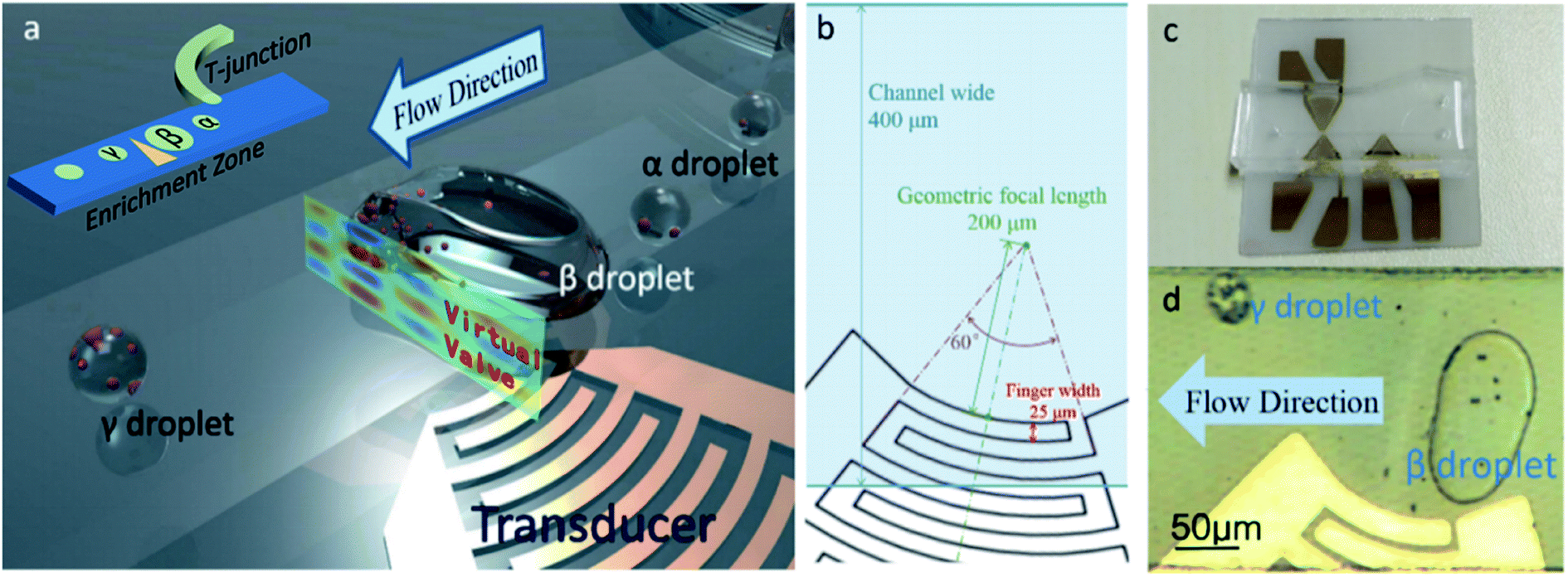 | ||
| Fig. 1 Device diagram and schematic diagram of enrichment method. (a) 3D diagram of intra-droplet particle enrichment method. The upper left corner is the schematic diagram of the whole channel, including T-junction and enrichment zone. (b) Detailed dimensions of the device around the enrichment zone. (c) Device photograph. (d) The photograph of the captured β droplet and released γ droplet. | ||
In experiments we found that most of the particles in the β droplet converged on the front edge of the droplet, hence, most of the particles would be enclosed in the newly produced γ droplets. The whole process can be thought of as putting particles in multiple α droplets into one γ droplet, thus achieving particle enrichment. After enrichment, there will be almost no particles left in the β droplets, then the acoustic field will be shut off, the β droplet will be released, and a new cycle will begin when next α droplet comes.
The device consists of a polydimethylsiloxane (PDMS) channel and a piezoelectric substrate with IDT. As shown in Fig. 1(b and c), the degree of arc of the IDT is 60° and the geometric focal length is 200 μm. The channel is 400 μm wide and about 45 μm high, and there is no additional coating on its surface. The piezoelectric substrate is 128° Y-cut, X-propagating lithium niobate (LiNbO3) substrate. Fluorocarbon oil (FC-40, biocompatible,27,28 containing 5‰ of surfactant) was used as a continuous phase fluid, and deionized water with polystyrene microspheres (7 μm, Rainbow®, Tianjin BaseLine Chromtech Research Center, China) were used as the dispersed phases.
Droplets are generated at the T-junction in the channel, and the size can be controlled according to the continuous phase velocity. The width of the dispersed phase channel in the T-junction is 40 μm. The acoustic field formed the enrichment zone in the channel, where droplets can be captured and merged, and particles in droplets can be enriched (Fig. 1(a and d)). The chip was fabricated by traditional MEMS method. The 30 nm Cr and 200 nm Au films of IDT were deposited by electron beam evaporation and the pattern was fabricated by the lift-off process. The PDMS micro channel of the microfluidic chip was manufactured with lithography method, and integrated together with the IDT using oxygen plasma bombardment.
The finger width and interspace of the IDT are 25 μm, and the resonance frequency of the IDT transducer on LiNbO3 substrate is about 39.96 MHz. However, because of the mismatch of acoustic impedance between the LiNbO3 substrate and the FC-40 in the channel, acoustic waves have different wavelengths in horizontal and vertical directions. In order to form resonance in the direction of channel height, the frequency of applied voltage is adjusted, because the unavoidable manufacturing errors can alter the resonance frequency of IDT after microfabrication. Hence, the frequency was set at around 36.3 MHz in the experiments, to make sure that in the vertical direction, the wavelength is about one quarter of the height of the channel, and at the same time, in the horizontal direction, the acoustic wave can be well focused. In some cases, the frequency needs to be adjusted to adapt to the height difference due to the microfabrication tolerance of the devices in different batches. Different frequencies are repeatedly attempted on different chips, and the frequencies that showed good capture performance range from 35 MHz to 40 MHz, but mostly around 36.3 MHz.
To generate the SAWs acting in the PDMS channel, an AC signal generated by an arbitrary signal generator (AFG3022, Tektronix, USA) was amplified with a power amplifier (BA4850, NF, JP) and applied to the IDT. The experiment was recorded by a microscope (LV100, Nikon, JP) and a CCD camera (DS-Fi1, Nikon, JP). The flow rate was regulated by a pressure pump (LSP01-2A, Longer Pump, CN).
3. Analysis of particle enrichment process
The enrichment was realized by capturing, merging and splitting droplets. The electrodes of the IDT was put under the channel, so acoustic waves can be transmitted directly to the medium (FC40). In our experiments, as shown in Fig. 2(a), especially when the acoustic field successfully form resonance, the droplets would stay close to the area where the acoustic field covers, showing a straight oil–water interface. In addition, there is an obvious “line” in the area where the acoustic field acts. This line is dim on both sides and bright in the middle, which is caused by the change of local refractive index. On the one hand, under the action of acoustic wave, the LiNbO3 substrate and PDMS produce acousto-optic effect, which makes the refractive index change obviously at the place with high sound pressure. On the other hand, the acoustic waves arising from the IDT generate pressure waves into the medium, whose density was modulated by these pressure waves. The medium in the high pressure region is compressed and the density increases, whereas in the negative pressure region, the opposite is true.29,30 The change of the density will lead to the change of refractive index. The final result is that the acoustic pressure field causes the change of the local refractive index of the medium.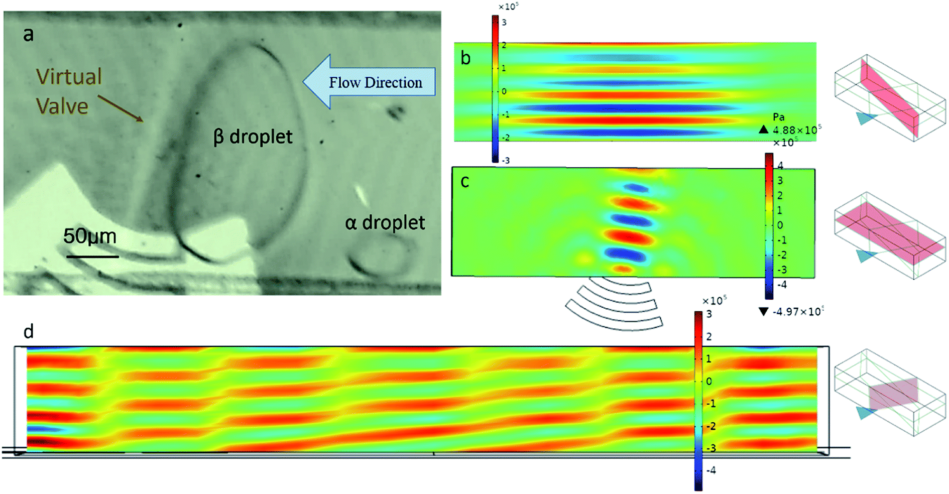 | ||
| Fig. 2 The photography of the virtual valve and its analysis. (a) Photograph of the captured β droplets and the virtual valve. And the side view (b), top view (c) and right view (d) of the simulation of the acoustic pressure field of the medium in the micro channel. | ||
The higher the voltage applied on the IDTs, the brighter the line, the better the trapping effect of droplets. Considering the capture-and-release process of droplets in the bright region of the acoustic field, we accordingly define this acoustic field and its acoustofluidic interactions as the virtual valve.
In the simulation (Fig. 2(b–d)), the diameters of the IDT and the channel is the same as those in the experiments, while the relative position between the IDT and the channel is changed in different simulation. In addition, the applied AC voltage was 35 V, the frequency is 36.3 MHz, and the flow was set to static. It can be seen that the acoustic pressure field has a good resonance in both the vertical and the horizontal plane of the channel. This makes a compact and stable acoustic field distribution in the channel. Under the effects of acoustic field and drag force, the β droplets grow up gradually and the γ droplets was separated. After that, most of the particles originally in the β droplet will be concentrated in the small γ droplets, as shown in Fig. 3(a and b).
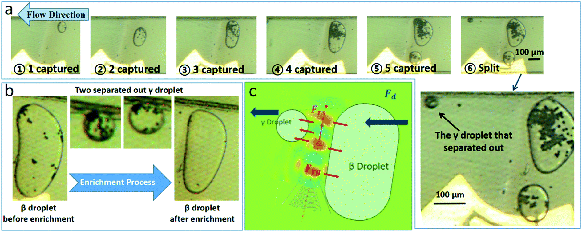 | ||
| Fig. 3 Intra droplet particle enrichment method. (a) β droplet was formed by several captured α droplets, and then γ droplet that is rich in particles was formed and separated. (b) After the whole enrichment process, there will be few particles left in β droplet. (c) Schematic diagram of β droplet forming γ droplet. | ||
The width of the acoustic pressure field perpendicular to the propagation direction of the surface acoustic wave is determined by the focused acoustic wave window size, which is the chord length of the front end of focused IDT. In the acoustic window region, the acoustic wave is focused in the horizontal plane and resonates in the height direction of the channel, so an acoustic pressure filed is formed. Outside the acoustic window region, however, the acoustic wave dissipates rapidly, resulting a pressure gradient in the flow direction. When the droplet is close to the acoustic window region, the high pressure acts on the interface between the droplets and the continuous phase, preventing the droplets from passing through the high acoustic pressure region or virtual valve.
The experimental results indicate it takes about 27 to 39 ms from a new α droplet get captured. In order to gain the best results of the enrichment, the generation rate of α droplet at the T-junction is controlled about 1 to 3 Hz under a continuous phase pressure of 7.5 kPa. Under this circumstance, particles have enough time to gather at the front edge of the β droplet before the next α droplet captured. It can be expected that if the generation of α droplets is fast enough that the particles do not have enough time to complete the aggregation, it may have an impact on the enrichment effect. Besides, faster droplet formation rate also means faster flow rate of the continuous phase and dispersed phase, which will increase the drag force of the continuous phase flow and make the acoustic field unable to capture the droplets, so the inlet pressures of continuous phase and dispersed phase were maintained below 10 kPa in the experiment for a better capture of the droplets.
Since there are great differences in acoustic impedance between the dispersed phase deionized water and the continuous phase fluorinated oil, the acoustic reflection effect is dominant over the acoustic transmission effect.24 Two components of the acoustic radiation force Fr, the acoustic scattering force Frs in the propagation direction and the acoustic gradient force Frg, have different effects on droplet capturing and splitting. Frg confronts the Fd acting on β droplets. The acoustic pressure field has a clear and orderly gradient distribution in the medium, causing the captured β droplet has a straight and clear oil–water interface, upon which, the Frg in the opposite direction of the flow direction causes the droplets captured along the edge of the acoustic pressure field (Fig. 3(c)). Drag force increases with the flow velocity, and get even higher when trapped β droplets block most of the channel. When the volume of the captured β droplet is large enough that the radius r of droplet cannot be neglected compared with the characteristic length of the channel, the drag force on the droplet will increase rapidly. In this experiment, the characteristic length is the hydraulic diameter dh of the channel, which is four times the vertical cross-sectional area of the channel divided by its perimeter. Compared to the normal Stokes drag force Fd, the drag force in the case where radius r cannot be neglected is defined as Fd2. Haberman and Sayre31 proposed the functional relationship between drag force Fd2 and normal Stokes drag force Fd:
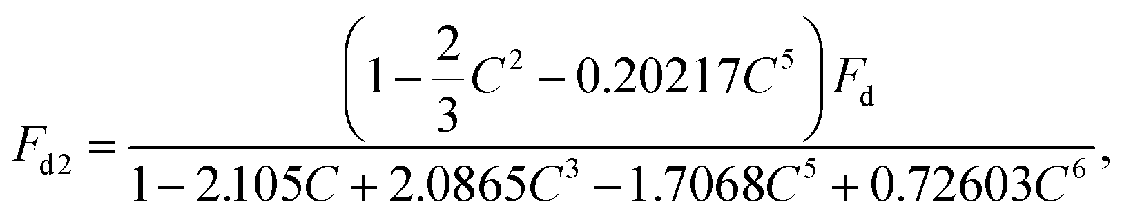 | (1) |
| Fd = 6πηυr, | (2) |
Based on the opposite forces of Frg on both sides, the virtual valve is actually the potential barrier constructed by Frg. When Fd2 is higher than the maximum Frg, a part of the β droplet will go cross the barrier. On the one hand, the deformation of the β droplet causes the drop of the r/dh and the Fd2; on the other hand, the opposite force Frg will eventually tear the β droplet apart along the center line of the acoustic pressure field, thus the γ droplet is generated.
When the flow velocity and applied voltage are constant, the equilibrium point of drag force Fd2 and acoustic gradient force Frg determines the upper limit of the volume of β droplet. The larger the β droplet is, the more particles can be wrapped in it and enriched in the γ droplet. When both Fd2 and Frg reach a high level, like when both the velocity and voltage are high at the beginning, and the volume of β droplet is close to the upper limit, very small γ droplets will be separated out, because the force balance in this system is unstable in this case. In other cases, the merge-in of a new α droplet can also cause the β droplet to spilt, and a new γ droplet will be separated out successively, but not as small as that in the former case.
4. Results and discussion
There are many factors like the average size of γ droplets, the maximum size of the captured β droplets, the particle density of original α droplets and so on that can affect the performance of particle enrichment.Compared with controlling the size of α droplets or γ droplets, the maximum size of captured β droplets is more controllable. As shown in Fig. 4, when the inlet pressure of the flow is 7.5 kPa, the average droplet velocity is 8.428 mm s−1, and the normal angle between the center line of the transducer and the channel wall is 15°, and when the voltage are 20 V, 40 V and 50 V, the maximum volume of the β droplets are 1.023 nL, 4.727 nL and 9.730 nL, respectively. It means that the maximum volume of the captured β droplet increases with the increase of the driving voltage. The volume of the droplet is estimated from its dimensional size based on imaging method. For the smaller droplets such as α and γ droplets, whose shape is regarded as a sphere, their volume are estimated using the formula of spherical volume. For the larger droplets like the captured β droplet, its volume is a sum of smaller droplets. The error of calculation is mainly from the image resolution and the determination of size.
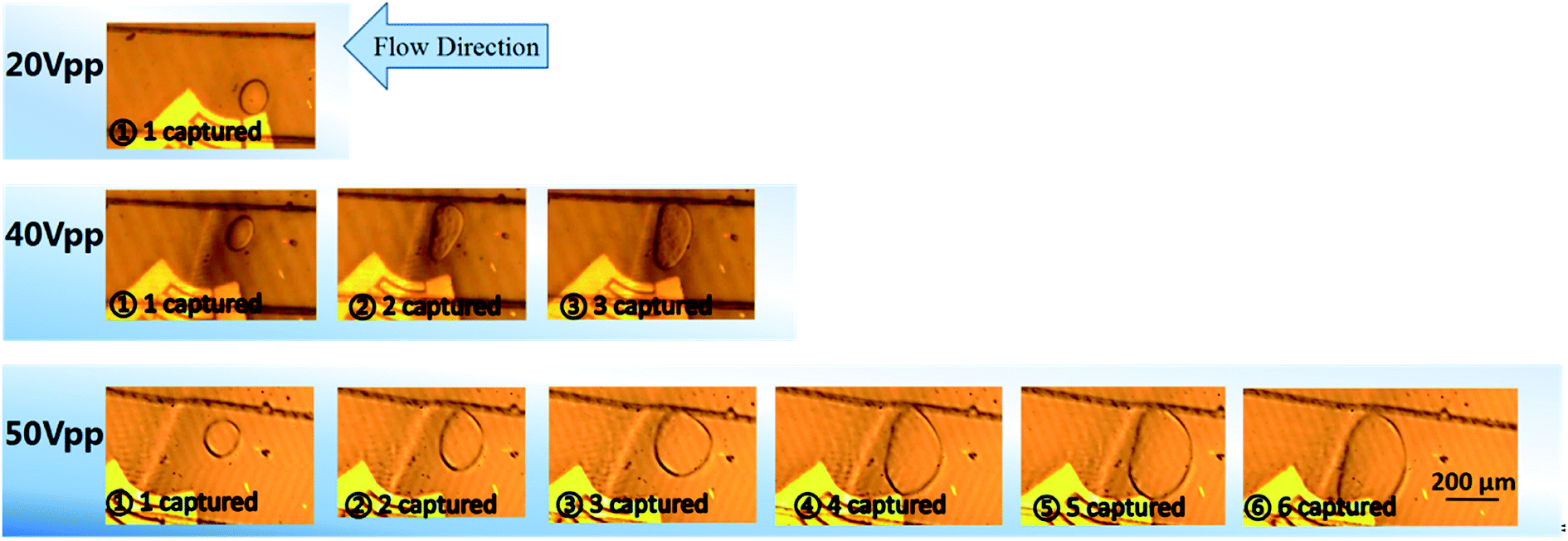 | ||
| Fig. 4 Photographs of captured droplets under different voltages. | ||
In addition to voltage, other factors also affect the maximum volume of β droplets. Suppose the normal angle between the center line of the transducer and the channel wall is θna, and distance between the midpoint of the front end of the electrode and the channel wall on the extended line of angular bisector is dmw (Fig. 5(a)). The pressure in the channel affects size and speed of α droplets, the dragging force and so on. The low pressure 2.8 kPa and the high pressure 6.0 kPa, as shown in Fig. 5(b), refer to the fluid pressure at the inlet of the channel. When the pressure is low, at the same voltage, the β droplets can reach a higher volume without new γ droplets split out.
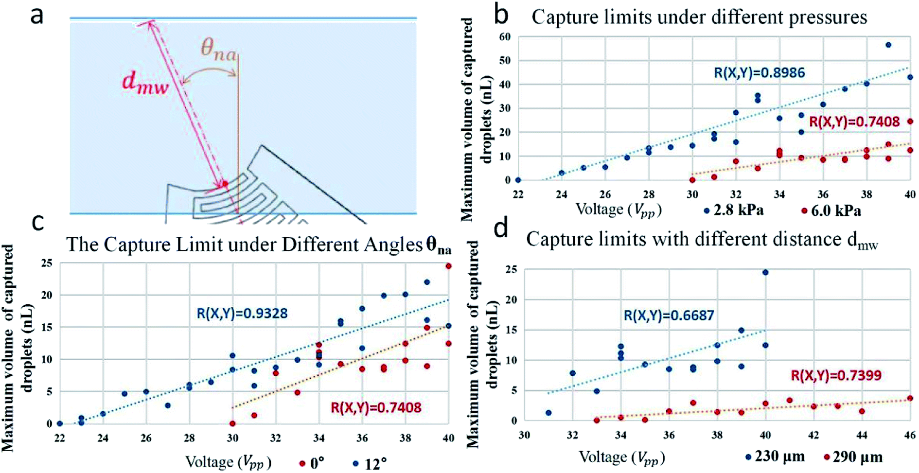 | ||
| Fig. 5 Capture capability limits of acoustic fields at different conditions. (a) The normal angle θna and distance dmw. And capture capacity under different voltages when given different conditions like: pressure at the inlet of the channel (b), normal angle θna (c) and distance dmw (d). (The blue and red dotted lines are the regression lines, and the R(X, Y) are the correlation coefficients.) The normal angle θna for the experimental results plotted in (d) is 11°, and the pressure in continuous phase is 6.0 kPa. | ||
When IDT shifts to a certain angle, the effect of acoustic field will be improved (Fig. 5(c)). The distance dmw is also an important factor affecting the capture effect. For example, the acoustic field with a distance of 230 μm has a better droplet capture effect than the case with a distance of 290 μm. However, if distance dmw is too short, the acoustic field will be difficult to focus. The factors such as voltage, pressure in channel, normal angle θna, distance dmw and so on determine the maximum size of captured β droplets. The larger the size limit of β droplets, the more potential the γ droplets have to encapsulate particles from more α droplets, so as to achieve better enrichment effect. The times of the increase of the number of particles per nanoliter in droplets before and after the enrichment process is regarded as the degree of enrichment. As shown in Fig. 6(a), when the voltage increases, the degree of enrichment also increase due to the increasing size of β droplets.
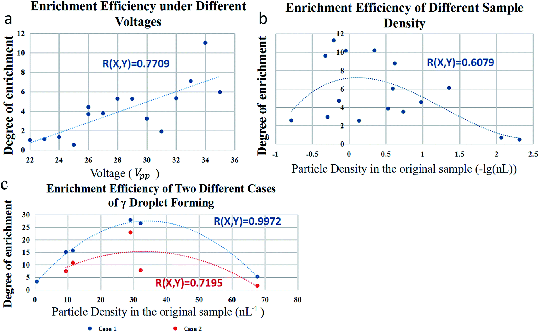 | ||
| Fig. 6 Enrichment performance of device under different conditions. (a) Particle enrichment capacity under different voltages. (b) Particle enrichment capacity under different particle density in original sample. X-axis is the logarithm of particle density. (c) Particle enrichment capacity of two different cases of γ droplet forming. Case 1 is γ droplet forming due to the instability of the balanced forces, and case 2 is γ droplet forming due to a new α droplet merging in (the blue and red dotted lines are the regression lines, and the R(X, Y) are the correlation coefficients). | ||
In addition to those physical and geometrical factors, particle density in the original sample can also affect the enrichment efficiency, which is increased first and then decreased with the increase of particle density. As shown in Fig. 6(b), this experiment is done under a voltage of 20 V, a pressure of 4.0 kPa, a normal angle of 18° and a distance dmw of 380 μm. Samples with low particle density are hard to enrich because there are fewer particles in β droplets, while the size of γ droplet still stay the same. Samples with high particle density are just the opposite, because too many particles makes it hard to encapsulate all of them in one γ droplet. In the experiment in Fig. 6, the particle diameter is 7 μm. The diameter of γ droplet is bigger in case 2, ranged from 45 μm to 120 μm. There is a limit to the number of particles that can be wrapped by the γ droplet. Even if there are enough particles gathered at the front edge of the β droplet, the γ droplet will not be able to wrap them all. Before being separated, the γ droplet is only a part of β droplet, that is to say, the front edge of β droplet is separated and becomes γ droplet. The experiment of particle enrichment can be understood as putting the particles in several α droplets into the same droplet. The more particles gather, the more space they take up. Of course, the γ droplet can be made into a large one. In the experiment, it can be realized by adjusting the voltage and other parameters. Larger γ droplets pack more particles, but they also reduce the number of particles per unit volume. The proportion of the particles wrapped in the first γ droplet to the particles in the original β droplet is about 71.34%. The particles in the droplet are counted by the imaging method. In the process of droplet movement, several different images are taken to calculate the average number of particles and hence the particle concentration in a single droplet.
Besides, the degree of particle enrichment achieved by the device is also related to the formation ways of γ droplets. As mentioned above, there are two cases that β droplet will generate γ droplets. Case 1 is that when the volume of β droplets reaches but not exceeds the limit of the acoustic field, the β droplets will emit very small γ droplets, due to the instability of the balanced forces; case 2 is that when the size of β droplet already exceeded the limit, like when the new α droplets merge into the big β droplets, it will generate a larger γ droplet. In case 2, the size of γ droplet is about 5.5% of that of β droplets (variance is 0.0014 in fifteen sets of data). In case 1, the size of γ droplets is about 0.3% of that of β droplets. Since the γ droplets produced by case 1 are smaller, its enrichment efficiency can be up to 26 times and that is better than case 2, as shown in Fig. 6(c), in which the voltage is 35 V, the pressure is 7.5 kPa, normal angle is 15° and distance dmw of 350 μm.
The degree of enrichment can be achieved by adjusting the conditions mentioned above. For different sample preparation experiments, different particle density will affect the enrichment effect. Thus, in the stage of device design, the parameters of normal angle θna and distance dmw can be determined according to particle density, so the range of enrichment ratio can be selected. Then, in the stage of experiment, we can adjust voltage and pressure to achieve a specific enrichment ratio, so as to achieve the controllable of the degree of enrichment.
It is noted that SAW exposure can cause temperature rise if the experiment last too long, which may damage biological samples like red blood cells. In the present experiments, the temperature was kept as stable as possible. The voltage applied in all tests is below 50 V to slow down the temperature rise, and the duration of the test is minimized. In the future work, we will try to reduce the impact of temperature factors.
5. Conclusion
We developed a method of particle enrichment in droplets based on focused acoustic field. The proposed focused acoustic field particle enrichment method achieves on-chip, label-free, selective, controllable and high enrichment ratio intra-droplet particle operation. In a simple microchannel, we have realized the controllable capture of different amounts of droplets with different sizes by changing several related factors like voltage, pressure, normal angle θna, distance dmw and particle density. Based on this, we have realized the different degree of particle enrichment in droplets. Under different conditions, the enrichment degree of this method ranged from 1 to 26 times. The device proposed in this study can be used as a sample processing and sample collection device before and after biochemical experiments, and has good adaptability and application prospects.Conflicts of interest
There are no conflicts of interest to declare.Acknowledgements
This project is financially supported by the National Natural Science Foundation of China (51575439 and 51711530237). We also appreciate the support from the International Joint Laboratory for Micro/Nano Manufacturing and Measurement Technologies and the State Key Laboratory for Manufacturing Systems Engineering (sklms2017006).References
- G. M. Whitesides, Lab Chip, 2012, 13, 11–13 RSC.
- J. Qiao, H. Ding, Q. Liu and R. Zhang, Anal. Chem., 2017, 89, 2080–2085 CrossRef CAS PubMed.
- D. Kang, X. Gong, S. Cho, J. Kim, J. B. Edel and S. Chang, et al., Anal. Chem., 2015, 87(21), 10770–10778 CrossRef CAS PubMed.
- P. S. Dittrich, K. Tachikawa and A. Manz, Anal. Chem., 2006, 78(12), 3887–3908 CrossRef CAS PubMed.
- N. N. Deng, Z. J. Meng, R. Xie, X. J. Ju, C. L. Mou and W. Wang, et al., Lab Chip, 2011, 11(23), 3963–3969 RSC.
- D. Spetzler, J. York, C. Dobbin, J. Martin, R. Ishmukhametov and L. Day, et al., Lab Chip, 2007, 7, 1633 RSC.
- J.-M. Lin, Integrated Analytical Systems, 2018, vol. 7, pp. 225–262 Search PubMed.
- W. Wu, S. Zhou, J. Hu, G. Wang, X. Ding, T. Gou and Y. Mu, Adv. Funct. Mater., 2018, 28, 1803559 CrossRef.
- S. Holler, C. Porcelli, I. A. Ieropoulos and M. M. Hanczyc, Sci. Rep., 2018, 8, 8408 CrossRef PubMed.
- A. Salari and M. Thompson, Sens. Actuators, B, 2018, 255, 3601–3615 CrossRef CAS.
- M. R. Ahmad, M. A. Mansor and I. L. Ahmad, IEEE-(IECBES) 2018, pp. 672–676 Search PubMed.
- J. V. Green, M. Radisic and S. K. Murthy, Anal. Chem., 2009, 81, 9178–9182 CrossRef CAS PubMed.
- K. Salimi, Ç. Kip, Ö. Çelikbıçak, D. D. Usta, A. Pınar, B. Salih and A. Tuncel, Biomed. Chromatogr., 2019, e4488 CrossRef PubMed.
- Y. Chen, S. Li, Y. Gu, P. Li, X. Ding, L. Wang and T. J. Huang, Lab Chip, 2014, 14, 924–930 RSC.
- M. Tenje, et al., Anal. Chem., 2018, 90(3), 1434–1443 CrossRef CAS PubMed.
- J. Shi, D. Ahmed, X. Mao, S. C. S. Lin, A. Lawit and T. J. Huang, Lab Chip, 2009, 9, 2890–2895 RSC.
- D. J. Collins, A. Neild and Y. Ai, Lab Chip, 2016, 16, 471–479 RSC.
- D. J. Collins, T. Alan and A. Neild, Appl. Phys. Lett., 2014, 105, 033509 CrossRef.
- K. Yasuda, S. -i. Umemura and K. Takeda, J. Acoust. Soc. Am., 1996, 1965–1970 CrossRef.
- T. L. Hoffmann and G. H. Koopmann, J. Acoust. Soc. Am., 1996, 2130–2141 CrossRef.
- A. Nilsson, et al., Lab Chip, 2004, 131–135 RSC.
- D. J. Collins, Z. Ma and Y. Ai, Anal. Chem., 2016, 88, 5513–5522 CrossRef CAS PubMed.
- A. Fakhfouri, C. Devendran, D. J. Collins, Y. Ai and A. Neild, Lab Chip, 2016, 16, 3515–3523 RSC.
- J. Park, G. Destgeer, H. Kim, Y. Cho and H. J. Sung, Lab Chip, 2018, 18, 2936–2945 RSC.
- J. H. Jung, G. Destgeer, B. Ha, J. Park and H. J. Sung, Lab Chip, 2016, 16, 3235–3243 RSC.
- A. Fornell, M. Ohlin, F. Garofalo, J. Nilsson and M. Tenje, Biomicrofluidics, 2017, 11, 031101 CrossRef PubMed.
- A. Prastowo, et al., Biomed. Microdevices, 2016, 18(6), 114 CrossRef PubMed.
- A. T. King, et al., Biotechnol. Tech., 1990, 4(3), 195–200 CrossRef CAS.
- L. Weiss, et al., J. Chem. Phys., 2012, 12, 124201 CrossRef PubMed.
- M. G. Scopelliti and C. Maysamreza, Light: Sci. Appl., 2019, 8(1), 65 CrossRef PubMed.
- W. Haberman, R. Sayre and D. Taylor, Model Basin Reports, 1958 Search PubMed.
| This journal is © The Royal Society of Chemistry 2020 |