
 Open Access Article
 This Open Access Article is licensed under a Creative Commons Attribution-Non Commercial 3.0 Unported Licence
Intrinsic dynamic and static nature of each HB in the multi-HBs between nucleobase pairs and its behavior, elucidated with QTAIM dual functional analysis and QC calculations†
Waro Nakanishi *,
Satoko Hayashi* and
Taro Nishide
*,
Satoko Hayashi* and
Taro Nishide
Faculty of Systems Engineering, Wakayama University, 930 Sakaedani, Wakayama 640-8510, Japan. E-mail: nakanisi@sys.wakayama-u.ac.jp; hayashi3@sys.wakayama-u.ac.jp; Tel: +81 73 457 8252
First published on 1st July 2020
Abstract
The intrinsic dynamic and static nature of each HB in the multi-HBs between nucleobase pairs (Nu–Nu′) is elucidated with QTAIM dual functional analysis (QTAIM-DFA). Perturbed structures generated using coordinates derived from the compliance constants (Cii) are employed for QTAIM-DFA. The method is called CIV. Two, three, or four HBs are detected for Nu–Nu′. Each HB in Nu–Nu′ is predicted to have the nature of CT-TBP (trigonal bipyramidal adduct formation through charge transfer (CT)), CT-MC (molecular complex formation through CT), or t-HBwc (typical HB with covalency), while the vdW nature is predicted for the C–H⋯X interactions, for example. Energies for the formation of the pairs (ΔE) are linearly correlated with the total values of Cii−1 in Nu–Nu′. The total Cii−1 values are obtained by summing each Cii−1 value, similarly to the case of Ohm's law for the parallel connection in the electric resistance. The total ΔE value for a nucleobase pair could be fractionalized to each HB, based on each Cii−1 value. The perturbed structures generated with CIV are very close to those generated with the partial optimization method, when the changes in the interaction distances are very small. The results provide useful insights for better understanding DNA processes, although they are highly enzymatic.
Introduction
Hydrogen bonds (HBs) are fundamentally important in all fields of chemical and biological sciences.1–9 The energy-lowering effect on the formation of HBs contributes to molecular association, and the formation of HBs controls the direction of the atoms taking part in HBs. One of the most important roles of HBs in biological sciences is the operation of the genetic code.10 The two helical chains of nucleotides in DNA associate through the multi-HBs between adenine–thymine (A–T) and guanine–cytosine (G–C) pairs, as proposed by Watson and Crick.3,10–13 The duplex DNA structure first opens and then closes in active proliferation at approximately room temperature, which is a typical event in DNA induced by the action of HBs. The processes must be highly enzymatically catalyzed.14 The multi-HBs between A–T and G–C pairs are formed in close proximity in space and will mutually and strongly interact with each other. Therefore, clarifying the nature of each HB in the multi-HBs between nucleobase pairs (Nu–Nu′), containing A–T and G–C, is very important. The results will provide useful insights for better understanding DNA processes, although they are highly enzymatic. The ability to image the initial stage of the opening and closing of duplex DNA through a simple mechanism based on the nature of each HB in the multi-HBs between Nu–Nu′ would be helpful. The basic behavior and stability of the duplex DNA structure should be closely related to the nature of each HB in Nu–Nu′. The ability to fractionalize the energy for the formation of Nu–Nu′ from the components (Nu and Nu′) to each HB in the multi-HBs between Nu–Nu′ is also very interested. Such considerations led us to elucidate the dynamic and static nature of each HB in the multi-HBs between Nu–Nu′, where the static nature of the interaction is calculated based on the fully optimized structure, while the dynamic nature is derived from the data of the perturbed structures around to the fully optimized one, which is explained later, again. Fig. 1 shows the structures of the nucleobases adenine (A), guanine (G), cytosine (C), thymine (T) and uracil (U) as molecular graphs, which are calculated with MP2/BSS-B′a (see Table 1 for BSS-B′a). Indeed, there are some possibilities in the structures of Nu–Nu′, and these possibilities, which control the functionalities of the pairs in the DNA chains, seem promising;15 however, the typical cases are discussed in this paper.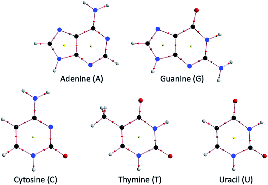 | ||
| Fig. 1 Molecular graphs for the nucleobases adenine (A), guanine (G), cytosine (C), thymine (T) and uracil (U), optimized with MP2/BSS-B′a (see Table 1 for BSS-B′a). | ||
| BSS | H, C, N, O | BSS | H, C, N, O |
|---|---|---|---|
| a The 6-311+G(3d) basis set being employed for C.b The 6-311+G(d) basis set being employed for C. | |||
| BSS-A | 6-311++G(3df,3pd) | BSS-A′ | 6-311+G(3df,3pd) |
| BSS-B′a | 6-311+G(3df,3pd)a | BSS-B′b | 6-311+G(3df,3pd)b |
| BSS-C | 6-311++G(3df,3p) | BSS-C′ | 6-311+G(3df,3p) |
| BSS-D | 6-311++G(3d,3p) | BSS-D′ | 6-311+G(3d,3p) |
The QTAIM approach, introduced by Bader,16,17 enables us to analyze the nature of chemical bonds and interactions.18–29 The bond critical point (BCP, *16,17,30) is an important concept in QTAIM corresponding to the point where ρ(r) (charge density) reaches a minimum along the interatomic (bond) path, while it is a maximum on the interatomic surface separating the atomic basins. ρ(r) at the BCP is denoted by ρb(rc) in this paper, as are other QTAIM functions, such as the total electron energy density Hb(rc), potential energy density Vb(rc) and kinetic energy density Gb(rc) at the BCP. A chemical bond or an interaction between A and B is denoted by A–B, which corresponds to the bond path (BP) in QTAIM. We use A–*–B for the BP, where the asterisk emphasizes the existence of a BCP in A–B.16,17,30 Eqn (1), (2) and (2′) represent the relations among Gb(rc), Vb(rc), Hb(rc), and ∇2ρb(rc).
| Hb(rc) = Gb(rc) + Vb(rc) | (1) |
| (ℏ2/8m)∇2ρb(rc) = Hb(rc) − Vb(rc)/2 | (2) |
| (ℏ2/8m)∇2ρb(rc) = Gb(rc) + Vb(rc)/2 | (2′) |
Interactions are classified by the signs of ∇2ρb(rc) and Hb(rc). Hb(rc) must be negative when ∇2ρb(rc) < 0, as confirmed by eqn (2), since Vb(rc) < 0 at all BCPs. Interactions are called shared shell (SS) interactions when ∇2ρb(rc) < 0 and closed-shell (CS) interactions when ∇2ρb(rc) > 0.16 In particular, CS interactions are called pure CS (p-CS) interactions when Hb(rc) > 0 and ∇2ρb(rc) > 0. We call interactions where Hb(rc) < 0 and ∇2ρb(rc) > 0 regular CS (r-CS) interactions, which clearly distinguishes these interactions from the p-CS interactions. The signs of ∇2ρb(rc) can be replaced by those of Hb(rc) − Vb(rc)/2 because (ℏ2/8m)∇2ρb(rc) = Hb(rc) − Vb(rc)/2 (see eqn (2)). Again, the details are explained later.
Experimental chemists have recently used QTAIM to explain their results by considering chemical bonds and interactions. Indeed, Hb(rc) − Vb(rc)/2 = 0 corresponds to the borderline between the classic covalent bonds of SS and the noncovalent interactions of CS, but Hb(rc) = 0 appears to be buried in the noncovalent interactions of CS. As a result, it is difficult to characterize the CS interactions of van der Waals (vdW) interactions, typical hydrogen bonds (t-HBs), interactions in molecular complexes formed through charge transfer (CT-MCs), trihalide ions (X3−), and interactions in trigonal bipyramidal adducts formed through CT (CT-TBPs), based on the signs of Hb(rc) − Vb(rc)/2 and/or Hb(rc). How can such CS interactions be classified and characterized effectively? It is essential for experimental chemists.
We proposed QTAIM dual functional analysis (QTAIM-DFA), based on the QTAIM approach, to classify and characterize the various CS interactions more effectively.31–36 QTAIM-DFA is very useful for experimental chemists to analyse their own chemical bond and interaction results based on their own expectations. In QTAIM-DFA, Hb(rc) are plotted versus Hb(rc) − Vb(rc)/2 at BCPs, which incorporates the classification of interactions by the signs of ∇2ρb(rc) [=(8m/ℏ2)(Hb(rc) − Vb(rc)/2)] and Hb(rc) (see, eqn (2)). In this treatment, both axes of the plot are given by the common unit of energy. As a result, four-function calculations can be applied to analyze the plot, which leads to the analysis of the interactions in a unified form.
The signs of the first derivatives of Hb(rc) − Vb(rc)/2 and Hb(rc) (d(Hb(rc) − Vb(rc)/2)/dr and dHb(rc)/dr, respectively, where r is the HB distance) are used to characterize CS interactions in QTAIM-DFA, in addition to those of Hb(rc) − Vb(rc)/2 and Hb(rc). In our treatment, data from the perturbed structures around the fully optimized structures are employed, in addition to those from the fully optimized structures. Data from the fully optimized structure are analyzed using polar coordinate (R, θ) representation, which corresponds to the static nature of interactions.32–37 Each interaction plot, containing data from both the perturbed and fully optimized structures, includes a specific curve that provides important information about the interaction. This plot is expressed by (θp, κp), where θp corresponds to the tangent line of the plot and κp is the curvature. θ and θp are measured from the y-axis and the y-direction, respectively. The concept of the dynamic nature of interactions has been proposed based on (θp, κp).32–37 We call (R, θ) and (θp, κp) QTAIM-DFA parameters (see Fig. 4 for the definition, as illustratively exemplified by NH–*–N of A–A).
How can the perturbed structures for effective analysis with QTAIM-DFA be generated? Accordingly, we very recently proposed a highly reliable method to the generate perturbed structures for QTAIM-DFA.38 The method, which is called CIV, employs the coordinates derived from the compliance constants Cii for internal vibrations.39,40 Eqn (3) defines Cij as the partial second derivative of the potential energy due to an external force, where i and j refer to internal coordinates and the external force components acting on the system fi and fj correspond to i and j, respectively.39 While the off-diagonal elements Cij (i ≠ j) in eqn (3) correspond to the compliance coupling constants, the diagonal elements Cii represent the compliance constants for an internal coordinate i.
| Cij = ∂2E/∂fi∂fj | (3) |
The Cij value given in eqn (3) corresponds to a lower numerical value (i) of a compliance constant representing a stronger bond (j); that is, Cij measures the flexibility (or compliance) of a particular bond. The applications of CIV to CS interactions are substantially more effective than those to SS interactions in QTAIM-DFA.38 The Cii values and the coordinates corresponding to Cii (Ci) were calculated using the Compliance 3.0.2 program, released by Grunenberg and Brandhorst.41–43 The dynamic nature of interactions based on the perturbed structures with CIV is described as the “intrinsic dynamic nature of interactions” since the coordinates are invariant to the choice of coordinate system. The mechanism for the formation the Nu–Nu′ pairs will also be clarified in more detail based on the Cii parameters.
QTAIM-DFA is applied to standard interactions, and rough criteria that distinguish the interaction in question from others are obtained. QTAIM-DFA has excellent potential for evaluating, classifying, characterizing, and understanding weak to strong interactions according to a unified form.32–37 QTAIM-DFA and the criteria are explained in the Appendix of the ESI using Schemes SA1–SA3, Fig. SA1, SA2, Table SA1 and eqn (SA1)–(SA7).† The basic concept of the QTAIM approach is also explained.
Indeed, the understanding of HBs has been considerably growing recently,1–9,44,45 but evaluating, characterizing, and understanding the nature of each HB in multi-HBs, especially in nucleobase pairs, is inevitably needed to obtain a better understanding of DNA processes. How can the dynamic and static nature of each HB in the multi-HBs between Nu–Nu′, where the multi-HBs are formed in close proximity in space and interact mutually and strongly with each other, be clarified? Grunenberg and Brandhorst calculated the strength of each HB of the multi-HBs in the A–T and C–G pairs by applying the compliance constants.42,46 The elucidation of the intrinsic dynamic and static nature of each HB in multi-HBs, exemplified by the acetic acid dimer and derivatives, was attempted by employing the perturbed structures generated with CIV to examine the effective applicability of QTAIM-DFA to the system.47
We consider QTAIM-DFA to be well suited to elucidate the nature of each HB in the multi-HBs between Nu–Nu′ by employing the perturbed structures generated with CIV, with above discussion in mind. The method enables us to classify and characterize the nature of the interaction and the results will be very useful when experimental chemists analyze their own chemical bond and interaction results based on their own expectations. This is another purpose of this work. Weak interactions in Nu–Nu′ may sometimes be called HBs in this paper, even if they should be assigned to other categories of interactions. Herein, we present the results of investigations on the intrinsic dynamic and static nature of each HB in the multi-HBs between nucleobase pairs. Each HB interaction in Nu–Nu′ can be classified and characterized effectively with QTAIM-DFA, employing the perturbed structures generated with CIV. The criteria are employed in this process as reference. The behavior of the pairs is also discussed based on the nature.
Methodological details in calculations
Calculations were performed employing the Gaussian 09 program package.48 Table 1 summarizes the basis set systems (BSSs) used in this paper. The Møller–Plesset second-order energy correlation (MP2) level49 was applied for the calculations, together with the DFT level of M06-2X.50,51 It was reported that MP2/BSS-A, MP2/BSS-A′, MP2/BSS-B′a, and MP2/BSS-B′b gave excellent results of very similar quality in the evaluation of the nature of each HB in the acetic acid dimer and related species.47 Optimized structures were confirmed by all real frequencies in the possible cases. The reliability of the structures optimized with MP2/BSS-B′a was also examined by comparison with structures optimized with MP2/BSS-A′. The results of the frequency analysis were used to obtain the Cii values and the coordinates corresponding to Cii (Ci). The M06-2X level was also employed, if necessary. The results obtained with MP2/BSS-B′a are mainly discussed in the text, while the results obtained with the other BSSs are mainly in the ESI.† BSS-D or lower basis sets were employed for pre-optimizations.Eqn (4) explains the method used to generate the perturbed structures with CIV. The i-th perturbed structure in question (Siw) is generated by the addition of the coordinates Ci, derived from Cii, to the standard orientation of a fully optimized structure (So) in the matrix representation. The coefficient giw in eqn (4) controls the structural difference between Siw and So: giw is determined to satisfy eqn (5) for r, where r and ro stand for the HB distances in the perturbed and fully optimized structures, respectively, and ao is the Bohr radius (0.52918 Å). The Ci values of five digits are used to predict Siw.
The perturbed structures were also generated by the partial optimization method (POM)31,33 of the Z-matrix and/or ModRedundant types,34 where the HB distances in question (r) in the perturbed structures were fixed to satisfy eqn (5).
| Siw = So + giw·Ci | (4) |
| r = ro + wao (w = (0), ±0.025 and ±0.05; ao = 0.52918 Å) | (5) |
| y = co + c1x + c2x2 + c3x3 | (6) |
QTAIM functions were calculated using the same method as in the optimizations, unless otherwise noted, and were analyzed with the AIM2000![[thin space (1/6-em)]](https://www.rsc.org/images/entities/char_2009.gif) 52 and AIMAll53 programs. Hb(rc) is plotted versus Hb(rc) − Vb(rc)/2 for five data points of w = 0, ±0.025 and ±0.05 in eqn (5). Each plot is analyzed using a regression curve of the cubic function, as shown in eqn (6), where (x, y) = (Hb(rc) − Vb(rc)/2, Hb(rc)) (Rc2 (square of the correlation coefficient) > 0.99999 is typical).37
52 and AIMAll53 programs. Hb(rc) is plotted versus Hb(rc) − Vb(rc)/2 for five data points of w = 0, ±0.025 and ±0.05 in eqn (5). Each plot is analyzed using a regression curve of the cubic function, as shown in eqn (6), where (x, y) = (Hb(rc) − Vb(rc)/2, Hb(rc)) (Rc2 (square of the correlation coefficient) > 0.99999 is typical).37
Results and discussion
Optimization of nucleobase pairs, Nu–Nu′
The nucleobase pairs are optimized with various BSSs at the MP2 and M06-2X levels, where many results have been reported.54 The HB distances (r(H, B); r) in Nu–Nu′ optimized with MP2/BSS-A′, MP2/BSS-B′a, MP2/BSS-B′b, M06-2X/BSS-A, M06-2X/BSS-C and M06-2X/BSS-D are collected in Table S1 of the ESI.† Energies for the formation of Nu–Nu′ from the components (Nu and Nu′) ΔE [=E(Nu–Nu′) − (E(Nu) + E(Nu′))] are evaluated with various methods. The ΔEES and ΔEZP values correspond to those on the energy surface and those containing the zero-point corrections, respectively. The values evaluated with MP2/BSS-B′a, MP2/BSS-B′b, M06-2X/BSS-A, M06-2X/BSS-C, and M06-2X/BSS-D are collected in Table S2 of the ESI,† which also contains the ΔEES values evaluated with MP2/BSS-A′. The results for the C1 structures of Nu–Nu′ (Nu–Nu′ (C1)) are mainly employed for the discussion, and the results for A–T (Cs), T–T (Ci) and U–U (Cs) are essentially the same as those for the corresponding C1 pairs. In the case of G–G, it is optimized as the Ci structure (see Table 2). The optimized structures are not shown in the figures, but they can be found in the molecular graphs drawn on the structures optimized with MP2/BSS-B′a (see Fig. 2).| AH–*–B in Nu–Nu′b (symmetry: no.c) | ρb(rc) (eao−3) | c∇2ρb(rc)d (au) | Hb(rc) (au) | Re (au) | θf (°) | Ciig (Å mdyn−1) | θph (°) | κpi (au−1) | Predicted nature |
|---|---|---|---|---|---|---|---|---|---|
| a See Table 1 for BSS-B′a.b Data are given at the BCPs.c Numbers given for the interactions are the same as those in Fig. 2 and 4.d c∇2ρb(rc) = Hb(rc) − Vb(rc)/2, where c = ℏ2/8m.e R = (x2 + y2)1/2, where (x, y) = (Hb(rc) − Vb(rc)/2, Hb(rc)).f θ = 90° − tan−1(y/x).g Defined in eqn (3) in the text.h θp = 90° − tan−1(dy/dx).i κp = |d2y/dx2|/[1 + (dy/dx)2]3/2. | |||||||||
| N–*–HN in A–T (C1: 1) | 0.0498 | 0.0094 | −0.0143 | 0.0171 | 146.7 | 3.12 | 182.4 | 8.5 | r-CS/CT-TBP |
| NH–*–O in A–T (C1: 2) | 0.0291 | 0.0114 | −0.0012 | 0.0115 | 95.9 | 5.78 | 145.4 | 115.3 | r-CS/t-HBwc |
| CH–*–O in A–T (C1: 3) | 0.0059 | 0.0025 | 0.0007 | 0.0026 | 74.5 | 16.31 | 80.6 | 64.9 | p-CS/vdW |
| N–*–HN in A–T (Cs: 4) | 0.0498 | 0.0094 | −0.0143 | 0.0171 | 146.7 | 3.12 | 182.4 | 8.5 | r-CS/CT-TBP |
| NH–*–O in A–T (Cs: 5) | 0.0291 | 0.0114 | −0.0012 | 0.0115 | 95.9 | 5.78 | 145.4 | 115.2 | r-CS/t-HBwc |
| CH–*–O in A–T (Cs: 6) | 0.0059 | 0.0025 | 0.0007 | 0.0026 | 74.5 | 16.30 | 80.6 | 64.9 | p-CS/vdW |
| NH–*–O in C–G (C1: 7) | 0.0449 | 0.0134 | −0.0096 | 0.0165 | 125.5 | 3.20 | 169.9 | 11.4 | r-CS/CT-MC |
| N–*–HN in C–G (C1: 8) | 0.0377 | 0.0099 | −0.0062 | 0.0117 | 122.2 | 2.15 | 175.0 | 30.8 | r-CS/CT-MC |
| O–*–HN in C–G (C1: 9) | 0.0305 | 0.0118 | −0.0017 | 0.0119 | 98.2 | 4.08 | 148.3 | 101.3 | r-CS/t-HBwc |
| NH–*–N in A–A (C1: 10) | 0.0289 | 0.0093 | −0.0018 | 0.0095 | 100.9 | 5.74 | 158.6 | 99.6 | r-CS/CT-MC |
| N–*–HC in A–A (C1: 11) | 0.0119 | 0.0045 | 0.0013 | 0.0047 | 74.1 | 17.10 | 75.6 | 55.8 | p-CS/vdW |
| N–*–HN in A–C (C1: 12) | 0.0391 | 0.0101 | −0.0071 | 0.0123 | 125.1 | 3.70 | 174.1 | 23.3 | r-CS/CT-MC |
| NH–*–O in A–C (C1: 13) | 0.0364 | 0.0135 | −0.0042 | 0.0141 | 107.5 | 3.72 | 158.2 | 40.2 | r-CS/CT-MC |
| N–*–HN in A–G (C1: 14) | 0.0424 | 0.0098 | −0.0091 | 0.0133 | 132.8 | 3.52 | 178.6 | 22.5 | r-CS/CT-MC |
| NH–*–O in A–G (C1: 15) | 0.0361 | 0.0125 | −0.0044 | 0.0133 | 109.5 | 4.45 | 161.0 | 45.0 | r-CS/CT-MC |
| CH–*–HN in A–G (C1: 16) | 0.0056 | 0.0026 | 0.0009 | 0.0027 | 71.1 | 29.31 | 78.8 | 111.5 | p-CS/vdW |
| N–*–HN in A–U (C1: 17) | 0.0500 | 0.0093 | −0.0145 | 0.0172 | 147.2 | 3.10 | 182.6 | 8.2 | r-CS/CT-TBP |
| NH–*–O in A–U (C1: 18) | 0.0289 | 0.0114 | −0.0011 | 0.0115 | 95.5 | 5.79 | 141.5 | 117.4 | r-CS/t-HBwc |
| CH–*–O in A–U (C1: 19) | 0.0060 | 0.0025 | 0.0007 | 0.0026 | 74.5 | 16.06 | 80.3 | 77.2 | p-CS/vdW |
| N–*–HN in C–C (C1: 20) | 0.0488 | 0.0099 | −0.0134 | 0.0167 | 143.5 | 2.63 | 180.6 | 2.3 | r-CS/CT-TBP |
| NH–*–O in C–C (C1: 21) | 0.0421 | 0.0131 | −0.0079 | 0.0153 | 121.0 | 3.86 | 168.1 | 17.8 | r-CS/CT-MC |
| O–*–HC in C–C (C1: 22) | 0.0050 | 0.0021 | 0.0006 | 0.0022 | 73.0 | 14.60 | 82.4 | 61.9 | p-CS/vdW |
| N–*–HN in C–T (C1: 23) | 0.0406 | 0.0096 | −0.0083 | 0.0127 | 130.7 | 4.77 | 178.1 | 24.7 | r-CS/CT-MC |
| NH–*–O in C–T (C1: 24) | 0.0348 | 0.0125 | −0.0037 | 0.0130 | 106.5 | 4.81 | 158.6 | 55.6 | r-CS/CT-MC |
| O–*–O in C–T (C1: 25) | 0.0026 | 0.0013 | 0.0006 | 0.0014 | 67.2 | 32.13 | 86.3 | 344.8 | p-CS/vdW |
| N–*–HN in C–U (C1: 26) | 0.0410 | 0.0096 | −0.0085 | 0.0129 | 131.6 | 4.73 | 178.5 | 23.5 | r-CS/CT-MC |
| NH–*–O in C–U (C1: 27) | 0.0347 | 0.0125 | −0.0036 | 0.0130 | 106.2 | 4.79 | 158.4 | 55.9 | r-CS/CT-MC |
| O–*–O in C–U (C1: 28) | 0.0028 | 0.0014 | 0.0006 | 0.0015 | 67.9 | 30.90 | 87.4 | 325.6 | p-CS/vdW |
| NH–*–O G–G (Ci: 29) | 0.0500 | 0.0136 | −0.0124 | 0.0184 | 132.4 | 2.86 | 172.4 | 7.6 | r-CS/CT-MC |
| O–*–HN G–G (Ci: 30) | 0.0083 | 0.0044 | 0.0015 | 0.0046 | 71.6 | 12.98 | 73.0 | 10.5 | p-CS/vdW |
| N–*–HN in G–T (C1: 31) | 0.0416 | 0.0100 | −0.0087 | 0.0133 | 130.8 | 3.90 | 177.1 | 19.7 | r-CS/CT-MC |
| NH–*–O in G–T (C1: 32) | 0.0335 | 0.0123 | −0.0030 | 0.0127 | 103.7 | 4.92 | 155.6 | 68.9 | r-CS/CT-MC |
| NH–*–O in G–U (C1: 33) | 0.0419 | 0.0138 | −0.0072 | 0.0155 | 117.5 | 3.09 | 165.7 | 21.7 | r-CS/CT-MC |
| O–*–HN in G–U (C1: 34) | 0.0404 | 0.0127 | −0.0070 | 0.0145 | 118.8 | 4.32 | 167.5 | 22.2 | r-CS/CT-MC |
| NH–*–O in T–T (C1: 35) | 0.0375 | 0.0129 | −0.0051 | 0.0139 | 111.4 | 4.29 | 163.5 | 34.1 | r-CS/CT-MC |
| O–*–HN in T–T (C1: 36) | 0.0375 | 0.0129 | −0.0051 | 0.0139 | 111.4 | 4.29 | 163.5 | 34.1 | r-CS/CT-MC |
| NH–*–O in T–T (Ci: 37) | 0.0375 | 0.0129 | −0.0051 | 0.0139 | 111.4 | 4.29 | 163.5 | 34.1 | r-CS/CT-MC |
| NH–*–O in T–U (C1: 38) | 0.0381 | 0.0130 | −0.0054 | 0.0141 | 112.6 | 4.17 | 164.2 | 30.9 | r-CS/CT-MC |
| O–*–HN in T–U (C1: 39) | 0.0366 | 0.0128 | −0.0046 | 0.0136 | 109.8 | 4.42 | 162.5 | 38.2 | r-CS/CT-MC |
| NH–*–O in U–U (C1: 40) | 0.0373 | 0.0129 | −0.0050 | 0.0138 | 111.1 | 4.29 | 163.3 | 34.5 | r-CS/CT-MC |
| O–*–HN in U–U (C1: 41) | 0.0373 | 0.0129 | −0.0050 | 0.0138 | 111.1 | 4.29 | 163.3 | 34.5 | r-CS/CT-MC |
| NH–*–O in U–U (Cs: 42) | 0.0373 | 0.0129 | −0.0050 | 0.0138 | 111.1 | 4.29 | 163.3 | 34.5 | r-CS/CT-MC |
| O–*–HN in U–U (Cs: 43) | 0.0373 | 0.0129 | −0.0050 | 0.0138 | 111.1 | 4.29 | 163.3 | 33.6 | r-CS/CT-MC |
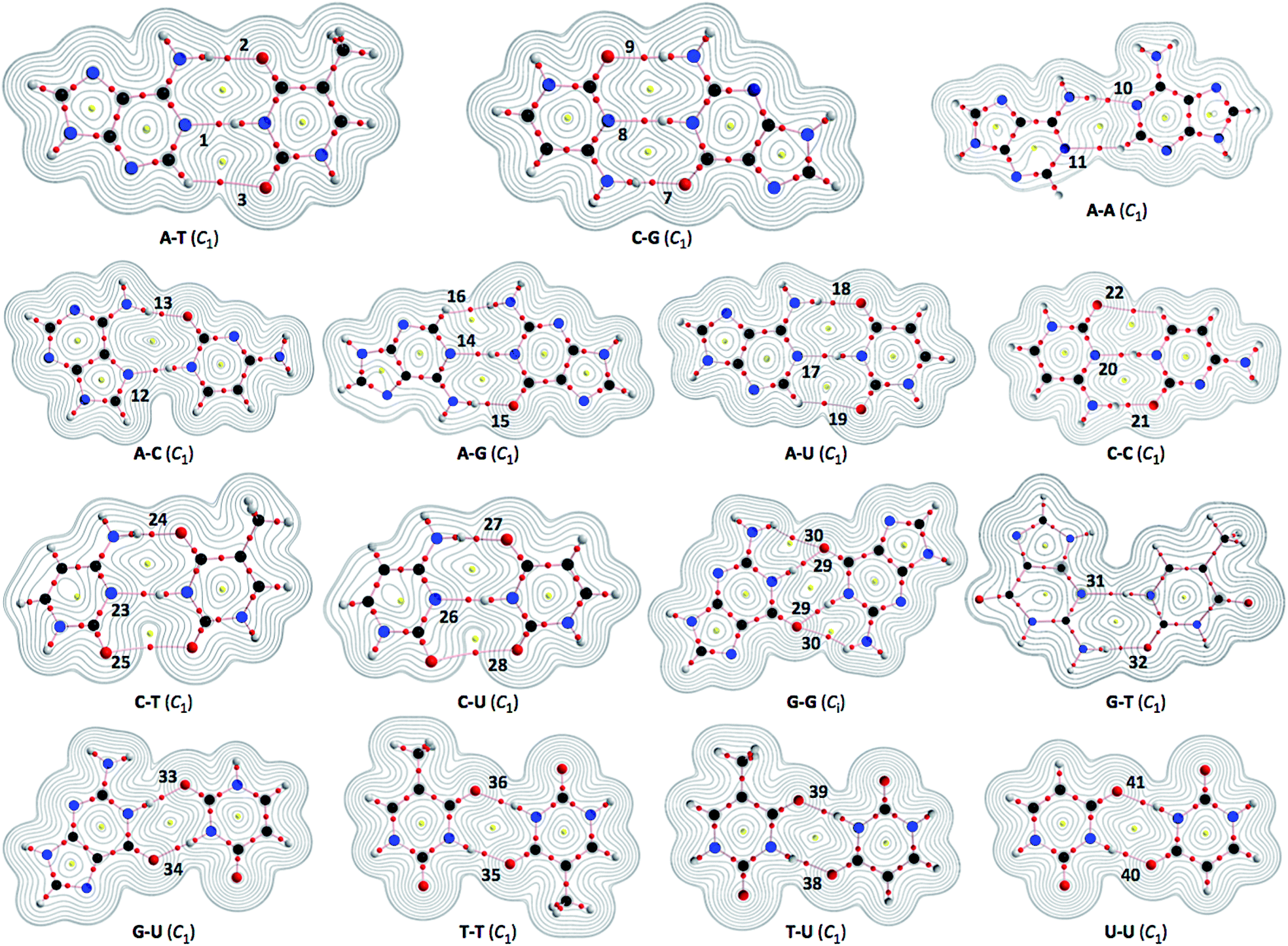 | ||
| Fig. 2 Molecular graphs for nucleobase pairs (Nu–Nu′), with the contour plots of ρ(r), evaluated with MP2/BSS-B′a. The numbers for the bonds are the same as those in Fig. 4 and Table 2. Bond critical points (BCPs) are denoted by red dots, ring critical points (RCPs) are denoted by yellow dots and bond paths (BPs) are denoted by pink lines. Oxygen, nitrogen, carbon and hydrogen atoms are in red, blue, black and gray, respectively. Contour plots are drawn on the planes containing at least one side of the HB interaction. The contours (eao−3) are at 2l (l = ±8, ±7, … and 0). | ||
The r(H, B) values in Nu–Nu′ evaluated with the various methods are plotted versus those evaluated with MP2/BSS-A′. The plot is shown in Fig. S1 of the ESI.† This plot gave very good correlations, as shown in the figure. The high similarities in r(H, B) correspond to the high similarities of the structures of Nu–Nu′ optimized with the methods employed in the calculations.43,46,55 The similarities are excellent, especially for the structures optimized with MP2/BSS-B′a, MP2/BSS-B′b and MP2/BSS-A′, although frequency analysis could not be performed on those with MP2/BSS-A′.
Molecular graphs with contour plots of ρ(r) and negative Laplacians around HBs in Nu–Nu′
Fig. 2 illustrates the molecular graphs with the contour plots of ρ(r) for Nu–Nu′ drawn on the structures optimized with MP2/BSS-B′a. As expected, a BP with a BCP is clearly detected for each HB. These BCPs seem well located at the (three-dimensional) saddle points of ρ(r). Fig. 3 shows the negative Laplacians of ρ(r), exemplified by A–T and C–G. All BCPs for HBs exist in the blue area (the outsides of the red area) in the figure, which means that the HBs in A–T and C–G are all classified as CS interactions.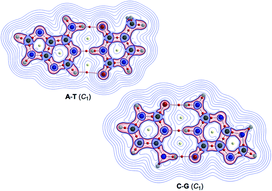 | ||
| Fig. 3 Negative Laplacians of ρ(r) for the A–T and C–G pairs, calculated with MP2/BSS-B′a. Positive and negative areas are in blue and red lines, respectively. | ||
For example, the ΔEES values evaluated with MP2/BSS-B′a are −70.3, −70.6 and −123.5 kJ mol−1 for A–T, A–U and C–G, respectively. The values for A–T and A–U are very close to each other due to their structural similarity.13 The ΔEZP values are plotted versus the ΔEES values calculated with MP2/BSS-B′a. The plot, which is shown in Fig. S2 of the ESI,† gives a very good correlation (ΔEZP = 0.968ΔEES + 1.80: Rc2 = 0.9993). Therefore, either ΔEES or ΔEZP can be employed for the discussion of the energy terms.
The nature of each HB in multi-HBs of Nu–Nu′ will be clarified by employing QTAIM-DFA.
Survey of the HB interactions in Nu–Nu′
The HB interactions in Nu–Nu′ seem straight, considering the BPs corresponding to the HBs shown in Fig. 2. To examine the linearity of the HB interactions further, the lengths of the BPs (rBP) in question and the corresponding straight-line distances (RSL) are calculated for Nu–Nu′. The values evaluated with MP2/BSS-B′a are collected in Table S3 of the ESI,† together with the differences between them (ΔrBP = rBP − RSL). The magnitudes of ΔrBP are less than 0.072 Å for the BPs; therefore, all HBs in Nu–Nu′ can be approximated by straight lines, except for CH–*–HN in A–G (ΔrBP: 0.1972 Å).QTAIM functions are calculated at each BCP on the BP corresponding to each HB in Nu–Nu′. Table 2 collects the ρb(rc), Hb(rc) − Vb(rc)/2 (=(ℏ2/8m)∇2ρb(rc)) and Hb(rc) values evaluated with MP2/BSS-B′a,46 where each HB in a nucleobase pair is numbered in the order of decreasing ρb(rc) values. Hb(rc) is plotted versus Hb(rc) − Vb(rc)/2 for the data shown in Table 2, together with those data from the perturbed structures generated with CIV. Fig. 4 illustrates the plots. Fig. 4a shows the whole picture of the plots, and Fig. 4b presents the magnified plots that appeared in the p-CS region of Hb(rc) − Vb(rc)/2 > 0 and Hb(rc) > 0. The data (points) in Fig. 4 are divided into three groups: (a) NH–*–N appeared in the r-CS region of Hb(rc) − Vb(rc)/2 > 0 and Hb(rc) < 0, (b) NH–*–O appeared in the r-CS region and (c) very weak O–*–O and CH–*–X (X = O, N and HN) interactions appeared in the p-CS region, where the weaker NH–*–O interaction in G–G (30) is also contained. The three groups are called G(A), G(B) and G(C), respectively, here. Relative to those from G(B), data from G(A) appear more on the left and lower sides overall. The results would show that interactions in G(A) are stronger than those corresponding to G(B) as a whole. As shown later, interactions in G(C) are predicted to have the vdW nature. The QTAIM-DFA parameters of (R, θ) and (θp, κp) are calculated for each HB in Nu–Nu′ by analyzing each plot shown in Fig. 4, according to eqn (SA3)–(SA6) of the ESI.† The (θp, κp) values calculated with CIV should be denoted by (θp:CIV, κp:CIV); however, we will use (θp, κp) in place of (θp:CIV, κp:CIV) for simplification of the notation. Table 2 collects the (R, θ) and (θp, κp) values evaluated with MP2/BSS-B′a, together with the Cii values related to the perturbed structures. Similar results calculated with the various methods other than MP2/BSS-B′a are collected in Tables S4 and S5 of the ESI.†
 | ||
| Fig. 4 Plots of Hb(rc) versus Hb(rc) − Vb(rc)/2 for each HB in Nu–Nu′, evaluated with MP2/BSS-B′a. For the whole picture (a) and the magnified image for the pure CS region (b). The numbers for the interactions are the same as those in Fig. 2 and Table 2, respectively. Two streams appear in the plots of (a) by NH–*–N and NH–*–O, which are shown by the solid and hollow marks, respectively. The definitions of (R, θ) and (θp, κp) are also illustrated. | ||
Each HB in Nu–Nu′ is classified and characterized based on the (R, θ, θp) values evaluated with MP2/BSS-B′a. The results are discussed in the following.
Nature of each HB in multi-HBs of Nu–Nu′
It is instructive to survey the criteria shown in Scheme SA3 and Table SA1 of the ESI† before a detailed discussion. While θ classifies interactions, θp characterizes them. The criteria tell us that 45° < θ < 180° (0 < Hb(rc) − Vb(rc)/2) for the CS interactions and that 180° < θ < 206.6° (Hb(rc) − Vb(rc)/2 < 0) for the SS interactions.37 The CS interactions are subdivided into 45° < θ < 90° (Hb(rc) > 0) for the p-CS interactions and 90° < θ < 180° (Hb(rc) < 0) for the r-CS interactions. In the p-CS region of 45° < θ < 90°, the interactions will be characterized as the vdW type when 45° < θp < 90° (45° < θ < 75°), whereas they will be considered typical hydrogen bonds (t-HB) with no covalency (t-HBnc) when 90° < θp < 125° (75° < θ < 90°), where θ = 75° and θp = 125° are tentatively given for θp = 90° and θ = 90°, respectively. The CT interactions appear in the r-CS region of 90° < θ < 180°. The interactions with the t-HBwc (t-HB with covalency) nature appear in the range of 125° < θp < 150° (90° < θ < 115°), where (θ, θp) = (115°, 150°) are tentatively given as the borderline between the t-HBwc and CT-MC (molecular complex formation through CT) interactions. The borderline between CT-MC and CT-TBP (TBP adduct formation through CT) interaction types is defined by (θ, θp) = (150°, 180°), where θ = 150° is tentatively given corresponding to θp = 180°. As a result, the (θ, θp) values of (75°, 90°), (90°, 125°), (115°, 150°), (150°, 180°) and (180°, 190°) correspond to the borderlines between vdW/t-HBnc, t-HBnc/t-HBwc, t-HBwc/CT-MC, CT-MC/CT-TBP and CT-TBP/Cov-w (weak covalent bond) interactions, respectively.The parameters given in bold are superior to those given in plain font in the classification and characterization of interactions, where those in plain font are given as the tentative ones. The classic chemical bonds of SS interactions (180° < θ) are not detected in the HBs collected in Table 2. As a result, each HB in Nu–Nu′ can be classified and characterized using the (θ, θp) values in place of (R, θ, θp). If the data of an HB appear in the CT-TBP region, for an example, the HB interaction is recognized to have the CT-TBP nature.
The (θ, θp) values are (67.2–74.5°, 73.0–87.4°) for O–*–O in C–U (28) and C–T (25); CH–*–O in C–C (22), A–T (3, 6) and A–U (19); CH–*–HN in A–G (16); CH–*–N in A–A (11); and the weaker O–*–HN in G–G (30). Therefore, the interactions are classified as p-CS interactions (45° < θ < 90°) and characterized as having the vdW nature (45° < θp < 90°), which is denoted by p-CS/vdW. The ∠NHO angle for the weaker NH–*–O interaction in G–G (30) is 135.0° (≪180°); therefore, it is much weaker than expected. The NH–*–O interactions in A–T (2, 5) and A–U (18) along with the weaker O–*–HN in C–G (9) are predicted to be r-CS/t-HBwc since the (θ, θp) values are (95.5–98.2°, 141.5–148.3°) (90° < θ; θp < 150°), although the weaker NH–*–O in C–G (9) seems fairly close to the borderline area with r-CS/CT-MC, of which (θ, θp) = (98.2°, 148.3°). The NH–*–O interactions in A–C (13), A–G (15), C–C (21), C–T (24), C–U (27), G–G (29), G–T (32), G–U (33, 34), T–T (35, 36, 37), T–U (38, 39) and U–U (40, 41, 42, 43), together with the stronger NH–*–O in C–G (7), are predicted to have the r-CS/CT-MC nature since the (θ, θp) values are (103.7–132.4°, 155.6–172.4°) (150° < θp < 180°). On the other hand, the (θ, θp) values for N–*–HN in A–T (1, 4), A–U (17) and C–C (20) are (143.5–147.2°, 180.6–182.6°); therefore, the interactions are predicted to have the r-CS/CT-TBP nature (θp > 180°), while the NH–*–N interactions in A–A (10), A–C (12), A–G (14), C–T (23), C–U (26) and G–T (31) along with the weaker NH–*–N in C–G (8) are predicted to be of the r-CS/CT-MC nature since (θ, θp) = (100.9–132.8°, 158.6–178.6°) (150° < θp < 180°). The NH–*–N interactions in A–G (14), C–T (23) and C–U (26) seem fairly close to the borderline area with r-CS/CT-TBP (θp = 180°) since the θp values are 178.6°, 178.1° and 178.5°, respectively, which are fairly close to 180°. The results are summarized in Table 2. The nature of each HB in the multi-HBs between Nu–Nu′, calculated with MP2/BSS-B′a, together with the number, is illustrated in Fig. S3 of the ESI.†
The total orders for NH–*–N and NH–*–O, based on θ and θp, are shown in eqn (7) and (8), respectively. The NH⋯N interactions are again demonstrated to be stronger than the NH⋯O interactions, overall. The orders shown in eqn (7) and (8) are similar with each other, although the similarity is not necessarily. These results would arise from the specific nature of each HB in multi-HBs of Nu–Nu′. The applicability of QTAIM-DFA, which employs the perturbed structures generated with CIV, is also demonstrated to elucidate the nature of each HB of the multi-HB system in Nu–Nu′. There are some differences, however. The differences in the orders are shown by italic. The differences seem large for NH–*–O (G–G: 29), NH–*–N (C–G: 8), NH–*–O (A–C: 13) and NH–*–N (A–A: 10), among them, as shown by italic.
For both NH–*–N and NH–*–O, based on θ:
| NH–*–N (A–U: 17) ≥ NH–*–N (A–T: 1) > NH–*–N (C–C: 20) > NH–*–N (A–G: 14) ≥ NH–*–O (G–G: 29) ≥ NH–*–N (C–U: 26) ≥ NH–*–N (G–T: 31) ≥ NH–*–N (C–T: 23) > NH–*–O (C–G: 7) ≥ NH–*–N (A–C: 12) > NH–*–N (C–G: 8) > NH–*–O (C–C: 21) > NH–*–O (G–U: 34) > NH–*–O (G–U: 33) > NH–*–O (T–U: 38) > NH–*–O (T–T: 35, 36) ≥ NH–*–O (U–U: 40, 41) > NH–*–O (T–U: 39) ≥ NH–*–O (A–G: 15) > NH–*–O (A–C: 13) > NH–*–O (C–T: 24) ≥ NH–*–O (C–U: 27) > NH–*–O (G–T: 32) > NH–*–N (A–A: 10) > NH–*–O (C–G: 9) > NH–*–O (A–T: 2) ≥ NH–*–O (A–U: 18) ≫ NH–*–O (G–G: 30) | (7) |
For both NH–*–N and NH–*–O, based on θp:
| NH–*–N (A–U: 17) ≥ NH–*–N (A–T: 1) > NH–*–N (C–C: 20) > NH–*–N (A–G: 14) ≥ NH–*–N (C–U: 26) ≥ NH–*–N (C–T: 23) > NH–*–N (G–T: 31) > NH–*–N (C–G: 8) > NH–*–N (A–C: 12) > NH–*–O (G–G: 29) > NH–*–O (C–G: 7) > NH–*–O (C–C: 21) > NH–*–O (G–U: 34) > NH–*–O (G–U: 33) > NH–*–O (T–U: 38) > NH–*–O (T–T: 35, 36) > NH–*–O (U–U: 40, 41) > NH–*–O (T–U: 39) > NH–*–O (A–G: 15) > NH–*–N (A–A: 10) > NH–*–O (C–T: 24) ≥ NH–*–O (C–U: 27) ≥ NH–*–O (A–C: 13) > NH–*–O (G–T: 32) > NH–*–O (C–G: 9) > NH–*–O (A–T: 2) > NH–*–O (A–U: 18) ≫ NH–*–O (G–G: 30) | (8) |
After elucidation of the nature of each HB in Nu–Nu′, the next extension is to consider the behavior of the HBs.
Relations between R, θ, θp and ρb(rc) for each HB in Nu–Nu′
Relations between the QTAIM-DFA parameters of (R, θ, θp) and QTAIM functions, such as ρb(rc), are examined, first.Good correlations are detected for the relations. The R values are plotted versus ρb(rc) for each HB in Nu–Nu′, as shown in Fig. S4 in the ESI.† The plot can be analyzed as three correlations of G(A), G(B), and G(C), which are closely related to the plot shown in Fig. 4. The data point for the weaker NH–*–O in G–G (30) is just on the correlation line for G(B); therefore, it is added to G(B) in the analysis. The correlations are shown in Table 3 (entries 1–3).
| Entry | Correlation | a | b | c | Correlation with n |
|---|---|---|---|---|---|
| a Evaluated with MP2/BSS-B′a.b Data from weaker NH–*–O of G–G (30) being added to G(B).c Omitting the data from weaker NH–*–O of G–G (30).d Omitting the data from C–G. | |||||
| 1 | R vs. ρb(rc) | 0.388 | −0.003 | 0.963 | Fig. S4 (G(A): 10) |
| 2 | R vs. ρb(rc) | 0.320 | 0.002 | 0.993 | Fig. S4(G(B): 20b) |
| 3 | R vs. ρb(rc) | 0.355 | 0.001 | 0.992 | Fig. S4 (G(C): 7c) |
| 4 | θ vs. ρb(rc) | 2110.5 | 42.5 | 0.985 | Fig. 5 (G(A): 10) |
| 5 | θ vs. ρb(rc) | 1811.6 | 43.4 | 0.989 | Fig. 5 (G(B): 19) |
| 6 | ΔE vs. (1/Cii)Nu–Nu′ | −121.1 | −7.52 | 0.954 | Fig. 6 (15) |
| 7 | ΔE vs. (1/Cii)Nu–Nu′ | −136.6 | −0.02 | 0.956 | Fig. 6 (14d) |
| 8 | (w′/w)POM vs. (w′/w)CIV | 1.021 | −0.001 | 0.9997 | Fig. 7 (15) |
| 9 | (w′/w)POM vs. (w′/w)CIV | 1.046 | −0.004 | 0.997 | Fig. S11 (15) |
The results seem to promise similar relations between the parameters. Fig. 5 shows the plot of θ versus ρb(rc). The plot is analyzed as three correlations for G(A) of NH–*–N, G(B) of NH–*–O and G(C) of vdW interactions. The correlations are shown in Table 3 (entries 4 and 5), except for the very poor correlation for G(C), which is given in the figure. The plot of θ versus R is illustrated in Fig. S5 of the ESI.† The plot is also analyzed as two correlations, similar to the case of the plot in Fig. 5. The correlations are given in the figure.
 | ||
| Fig. 5 Plots of θ versus ρb(rc) for each HB in Nu–Nu′, calculated with MP2/BSS-B′a. While data for G(A) of NH–*–N are shown by black solid circles, those for G(B) of NH–*–O are by red solid circles, together with those for G(C) of CH–*–X (X = O, N and HN) and O–*–O by blue hole circles. The numbers for the interactions are the same as those in Table 2 and Fig. 4. | ||
Good linear correlations are not found in the plots of θp versus ρb(rc) and θp versus R. The plot of θp versus θ also does not give a good linear correlation. Instead, the relation between θp and θ is analyzed using a cubic function as a regression curve. The correlation was much improved when analyzed as two correlations, which are shown in Fig. S6 of the ESI.† The correlations are given in the figure.
Relations between ΔE and Cii for Nu–Nu′
We reported a good inverse correlation between ΔE and Cii (ΔE·Cii = constant) for the neutral mono-HB species.45 Therefore, eqn (9) is expected to hold between ΔE and 1/Cii in the multi-HB system of Nu–Nu′, where 1/Cii should be the total values for Nu–Nu′, together with ΔE. How can the total values of 1/Cii for the multi-HBs of Nu–Nu′ be calculated from the value of each HB in Nu–Nu′? Eqn (10) is applied for the purpose, where (1/Cii)Nu–Nu′ is the total value of 1/Cii for a nucleobase pair and (1/Cii)Nu–Nu′:k is the 1/Cii value for the k-th HB in the nucleobase pair. The (1/Cii)Nu–Nu′:k values of the vdW interactions are also contained in the summation.| ΔE = a(1/Cii) + b | (9) |
| (1/Cii)Nu–Nu′ = Σk(1/Cii)Nu–Nu′:k | (10) |
The ΔE values are plotted versus (1/Cii)Nu–Nu′ for Nu–Nu′ in Fig. 6. A (very) good correlation was obtained for the plot, which is shown in Table 3 (entry 6). In this case, a y-intercept value (b in eqn (9)) very close to zero is obtained (b = 0.02 kJ mol−1) if data from C–G are omitted from the correlation, although the correlation seems not very improved. The correlation is shown in Table 3 (entry 7). The inverse proportion also holds for the multi-HB system of Nu–Nu′ in this case. The constant value (in ΔE·Cii = constant), as the averaged value of ΔE·Cii for Nu–Nu′, is evaluated to be −137.04 without C–G. The constant value for Nu–Nu′ (−137.04) is close to but somewhat smaller than that reported for the neutral mono-HB species (−165.64) in magnitude.45 The constant value for all Nu–Nu′ is evaluated to be −135.96, which is very close to that without the data from C–G. The results show that the compliance constants (Cii) are closely related to ΔE for the formation of not only the neutral mono-HB species but also the multi-HB system of Nu–Nu′. A similar mechanism would be operative in both processes of ΔE and Cii in the multi-HB systems of Nu–Nu′. Eqn (10) reminds us that the total value of resistance of a parallel connection should be calculated for each one according to Ohm's law for the electric resistance of resistors connected in parallel.56
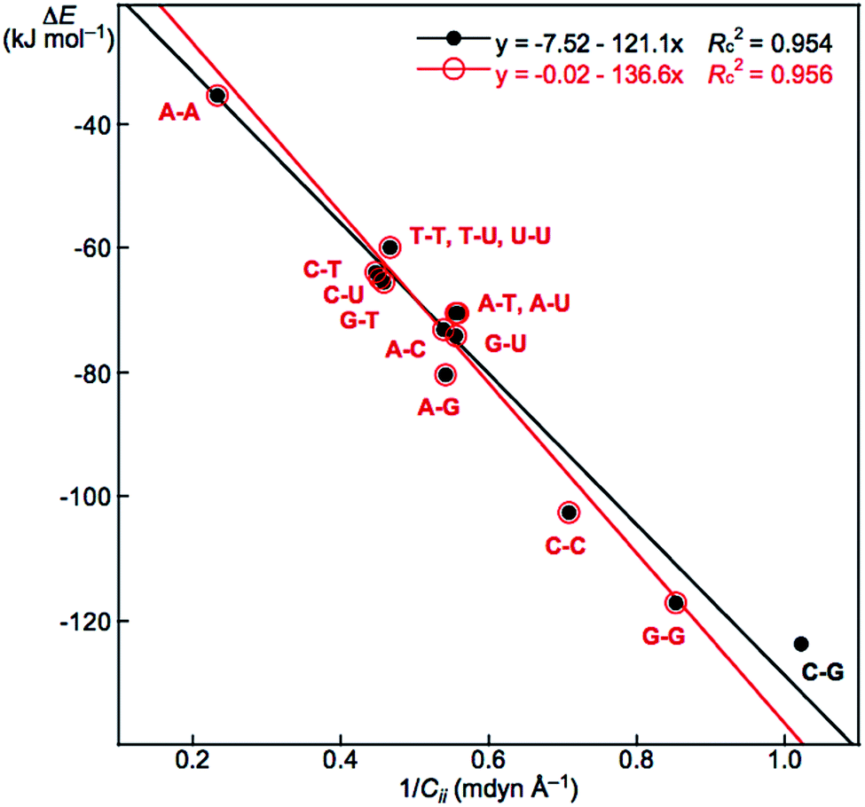 | ||
| Fig. 6 Plot of ΔE versus (1/Cii)Nu–Nu′ in Nu–Nu′, calculated with MP2/BSS-B′a. | ||
The total contributions of ΔE and Cii should be calculated as the summations of the contributions from each HB. As a result, it is expected that the ΔE value for a nucleobase pair can be fractionalized to each HB in the multi-HB system of the Nu–Nu′. Based on the good relation with eqn (9) and (10) shown in Fig. 6 (see entry 6 or 7 in Table 3), the ΔE value for a nucleobase pair is expected to be fractionalized to each HB (ΔEe) by the ratio of 1/Cii of each HB, according to eqn (11), where ΔEe:1 and (1/Cii)Nu–Nu′:1 stand for the fractionalized energy to the first HB and for the 1/Cii value of the first HB in the Nu–Nu′, respectively. The results are collected in Table 4.
| ΔEe:1:ΔEe:2:… = (1/Cii)Nu–Nu′:1:(1/Cii)Nu–Nu′:2:… | (11) |
| Nu–Nu′ (sym) | ΔE | ΔEe (no.b) | ΔEe (no.b) | ΔEe (no.b) |
|---|---|---|---|---|
| a The values are given in kJ mol−1.b The number for each HB, containing the vdW interaction, is the same as that given in Table 2. | ||||
| A–T (C1) | −70.3 | −40.6 (1) | −21.9 (2) | −7.8 (3) |
| C–G (C1) | −123.5 | −37.7 (7) | −56.2 (8) | −29.6 (9) |
| A–A (C1) | −35.4 | −26.5 (10) | −8.9 (11) | |
| A–C (C1) | −73.1 | −36.6 (12) | −36.5 (13) | |
| A–G (C1) | −80.5 | −42.1 (14) | −33.3 (15) | −5.1 (16) |
| A–U (C1) | −70.6 | −40.8 (17) | −21.9 (18) | −7.9 (19) |
| C–C (C1) | −102.6 | −55.1 (20) | −37.6 (21) | −9.9 (22) |
| C–T (C1) | −64.0 | −29.9 (23) | −29.7 (24) | −4.4 (25) |
| C–U (C1) | −64.9 | −30.3 (26) | −29.9 (27) | −4.6 (28) |
| G–G (Ci) | −117.1 | −48.0 (29) | −10.6 (30) | |
| G–T (C1) | −65.4 | −36.5 (31) | −28.9 (32) | |
| G–U (C1) | −74.2 | −43.3 (33) | −30.9 (34) | |
| T–T (C1) | −60.0 | −30.0 (35) | −30.0 (36) | |
| T–U (C1) | −59.9 | −30.8 (38) | −29.1 (39) | |
| U–U (C1) | −59.8 | −29.9 (40) | −29.9 (41) | |
Similar relation is also observed in the di-HB system of acetic acid dimer and the related species. The results are explained in Fig. S7 and Table S6 of the ESI.†
The mutual interactions between HBs must also be of very importance in the multi-HBs of Nu–Nu′, which would be clarified through the detailed analysis of Cij (i ≠ j) for the multi-HBs.46a
Relations among the total values of R, θ, θp and ΔE for Nu–Nu′
What are the relations among the total values of R, θ, θp and ΔE for Nu–Nu′? The total values of PNu–Nu′ (=RNu–Nu′, θNu–Nu′ and θp:Nu–Nu′) of Nu–Nu′ are necessary for the analysis. The total values are calculated according to eqn (12), where PNu–Nu′:k is the PNu–Nu′ value for each HB in Nu–Nu′. The PNu–Nu′:k values from the vdW interactions are also contained in eqn (12).| PNu–Nu′ = ΣkPNu–Nu′:k | (12) |
The ΔE values are plotted versus RNu–Nu′, θNu–Nu′ and θp:Nu–Nu′, and the plots are shown in Fig. S8–S10 of the ESI.† The correlation is greatly improved by analyzing the plot as two or three correlations instead of one correlation. The correlations are shown in the figure. The correlation for ΔE versus θp:Nu–Nu′ seems poorer than that for ΔE versus θNu–Nu′.
It is also instructive to clarify the structural feature in the perturbed structures of Nu–Nu′ to discuss the behavior of each HB of Nu–Nu′ in more detail, which is examined in the following.
Structural feature in the perturbed structures of Nu–Nu′
How can the perturbed structures of Nu–Nu′ generated with CIV and POM be simply and effectively visualized? Eqn (13)–(15) are applied to a tri-HB system for the purpose. Subscribes 1, 2 and 3 in eqn (13)–(15) correspond to the first, second and third HBs in tri-HBs of Nu–Nu′, while k (=1, 2 and 3) designates the role of each HB in the calculations. In eqn (13), rk1 will be r11 when k = 1, which means that the first HB in Nu–Nu′ is selected as the major HB and therefore is fixed in POM. In this case, relative to r11, r12 for the second HB in eqn (14) and r13 for the third HB in eqn (15) (k = 1) are the minor HBs, which are (partially) optimized in POM. Similarly, eqn (14) defines r22 with k = 2, and eqn (15) does r33 with k = 3, where the second and third HBs are selected as the major interactions, respectively, for Nu–Nu′. Compared to r22, the r21 and r23 values are the minor HBs, while compared to r33, r31 and r32 are the minor HBs. The wk1, wk2 and wk3 values are calculated according to eqn (13)–(15), where w11, w22 and w33 are the fixed values. Eqn (13) and (14) with k = 1 and 2 are applied to the di-HB system of Nu–Nu′.| rk1 = rk1o + wk1ao | (13) |
| rk2 = rk2o + wk2ao | (14) |
| rk3 = rk3o + wk3ao | (15) |
The structural feature in the perturbed structures of Nu–Nu′ is examined by dividing them into four groups, G(AT), G(CG), G(AA) and G(TT).57 Nu–Nu′ of A–T, C–G, A–A and T–T are the typical members of the groups, respectively. The feature is discussed by employing A–T, C–G, A–A and T–T, together with U–U. The feature in UU will supply a small structural difference from that in TT, although UU belongs to G(TT).
The values of  and
and  are calculated for each HB in A–T, C–G, A–A, T–T and U–U with MP2/BSS-B′a at wii = 0.05 by applying in eqn (13)–(15).32–38 The values are collected in Table S7 of the ESI.† Small differences in
  between T–T and U–U are detected. A positive value of
  implies that the minor (HB) interaction in Nu–Nu′ moves in the same direction as the major interaction. On the other hand, relative to the major interaction, the minor HB interaction moves in the inverse direction for negative
  values. Compared to that of the major interaction, the magnitudes in the movement of the minor HB interactions would be negligible when the
  values are close to zero. Fig. 7 shows the plot of
  versus
  for the HB interactions. The plot gave an excellent correlation, which is shown in Table 3 (entry 8). The results show that the perturbed structures generated with CIV and POM are very close to each other, approximately at wii = 0.05, in the multi-HB system of Nu–Nu′, as well as in the case of the mono-HB system.45
 | ||
Fig. 7 Plot of  versus versus  for each HB of multi-HB system in A–T, C–G, A–A, U–U and T–T, calculated at wii = 0.05 with MP2/BSS-B′a. for each HB of multi-HB system in A–T, C–G, A–A, U–U and T–T, calculated at wii = 0.05 with MP2/BSS-B′a. | ||
What happens if the H⋯B distance (r(H, B)) in each HB of Nu–Nu′ is elongated further, where Δr(H, B) (=r(H, B) − ro(H, B)) is defined as the difference in H⋯B distance between the perturbed structure and the fully optimized structure. Relative to that of M06-2X/BSS-A, the reliability of M06-2X/BSS-C′ is confirmed for the optimizations. That is, the ro(H, B) values calculated with M06-2X/BSS-C′ differ from the corresponding values calculated with M06-2X/BSS-A by less than 0.01 Å in magnitude (see Table S1 of the ESI†). Therefore, these perturbed structures are calculated with POM by fixing the r(H, B) distances in question in the wider range of −0.05 Å ≤ Δr(H, B) ≤ 0.50 Å for all HBs in A–T, C–G, A–A, T–T and U–U with M06-2X/BSS-C′ for improved calculation cost. The results are summarized in Table S8 of the ESI† in the  form. The ΔEESps (=EESps − EESo) values are also calculated for each HB in A–T, C–G, A–A, T–T and U–U based on the partially optimized structures. The EESps values are the energies of the perturbed structures at r(H, B) on the energy surface, and the EESo values are those for the fully optimized structures. The magnitudes of the differences between ΔEESps calculated with M06-2X/BSS-C′ and those calculated with M06-2X/BSS-A are less than 0.3 kJ mol−1 for A–T, C–G, A–A, T–T and U–U if the corresponding values are compared at Δr(H, B) = 0.025 Å (see Table S3 of the ESI†). The results again support the reliability of M06-2X/BSS-C′ relative to M06-2X/BSS-A in the optimizations.
The perturbed structures of A–T, C–G, A–A, T–T and U–U are also generated by employing CIV with M06-2X/BSS-C′ in a wider range of −0.1 ≤ wii ≤ 1.0 (cf.: −0.05 Å ≤ Δr ≤ 0.50 Å for POM). The wij values of the minor HBs are calculated, corresponding to wij at wii = 0.05 for the Nu–Nu′. The results are also summarized in Table S8 of the ESI† in the  form. The
  values are plotted versus
  calculated at wii = 0.05 with M06-2X/BSS-C′, as shown in Fig. S11 of the ESI.† The plot also gives a very good correlation, which is shown in Table 3 (entry 9). The quality of the correlation based on M06-2X/BSS-C′ is noticeably the same as that of the correlation based on MP2/BSS-B′a.
The ΔEESps values are plotted versus a wide range of −0.05 Å ≤ Δr(H, B) ≤ 0.50 Å and −0.1 ≤ wii ≤ 1.0 for each HB in A–T, C–G, A–A, T–T and U–U evaluated with POM and CIV, respectively. The plot is illustrated in Fig. S12 of the ESI,† where r(H, B) in the x axis with POM is replaced by wii. As shown in the figure, the differences in ΔEESps between the structures evaluated with CIV and those evaluated with POM are negligible at approximately wii < 0.2. Indeed, the ΔEESps curves evaluated with CIV show a similar trend as those evaluated with POM for wii < 0.3, but overall, the curves begin to grow rather exponentially for wii > 0.4 as wii increases. The results show that the perturbed structures generated with POM and CIV are very similar for wii < 0.2 and similar for 0.2 < wii < 0.3 but become different for 0.4 < wii.
The gradient for ΔEESps is largest for N–H⋯N in C–G, which must be the reflection of the largest magnitude of ΔEES for C–G (−117.2 kJ mol−1) among A–T, C–G, A–A, T–T and U–U. The gradient for ΔEESps decreases in the order shown in eqn (16). The order seems to not necessarily reflect the strength of each HB in the A–T and C–G pairs.
| N–H⋯N (C–G) ≫ N–H⋯O (C–G) ≥ O⋯H–N (C–G) > N–H⋯N (A–T) > N–H⋯O (U–U) > N–H⋯O (T–T) > N–H⋯N (A–A) ≈ N–H⋯O (A–T: j = 1) > C–H⋯N (A–A) > N–H⋯O (A–T: j = 3) | (16) |
The gradient increased when POM or CIV is applied to the central N–H⋯N interaction for both the A–T and C–G pairs. The behavior of ΔEESps evaluated with POM may correspond to that in the initial stage for the scission of Nu–Nu′ to Nu and Nu′ under the simple mechanism for each HB. Such large ΔEESps values must be effectively decreased by the enzyme-catalyzed reactions in vivo at approximately room temperature. However, it is helpful to understand the behavior of HBs in Nu–Nu′ through a simple mechanism.
Indeed, the behavior of HBs, containing those of multi-HBs in Nu–Nu′, will be revealed in more detail, if the magnitudes in the movement of HBs is directly investigated. The NVT ensemble method seems typical one of such methods.58 The predicted nature will change depending on the quality of the calculation levels, especially for weak HBs. However, the results in the framework of QTAIM-DFA with CIV should be reasonable, if calculated with MP2/BSS-B′a.
Conclusions
The intrinsic dynamic and static nature of each HB in the multi-HBs of Nu–Nu′ is elucidated with QTAIM-DFA by employing the perturbed structures generated using the coordinates derived from the compliance constants Cii. The method is called CIV. The initial stage of the opening or closing of the duplex DNA structure and the stability can be understand based on the nature of the interactions through the simple mechanism. In QTAIM-DFA, Hb(rc) is plotted versus Hb(rc) − Vb(rc)/2 for the data of each HB at the BCP in Nu–Nu′, containing those from the perturbed structures generated with CIV. The plot consists of three groups of data: G(A) of NH–*–N, G(B) of NH–*–O and G(C) of the very weak interactions of the vdW type. The plot is analyzed to give the QTAIM-DFA parameters of (R, θ) and (θp, κp), which correspond to the static and intrinsic dynamic nature, respectively. Each NH–*–N in G(A) is predicted to have the nature of r-CS/CT-MC to r-CS/CT-TBP, and each NH–*–O in G(B) is of the nature of r-CS/t-HBwc to r-CS/CT-MC. The results show that NH–*–N in G(A) is stronger than NH–*–O in G(B) overall. It is demonstrated that the total values of ΔEES are (directly) proportional to (1/Cii)Nu–Nu′, the total values of 1/Cii for Nu–Nu′, where (1/Cii)Nu–Nu′ is calculated by Σk(1/Cij)Nu–Nu′:k, similar to Ohm's law for a parallel connection. The results demonstrate that ΔEES values are closely related to Cii values. As a result, the total value of ΔEES for Nu–Nu′ can be fractionalized to each HB in multi-HB systems, even if the HBs in multi-HB systems, containing the weak vdW interactions, are formed in close proximity in space and interact mutually and strongly with each other. The results of the fractionalizations are shown in Table 4. The differences in the perturbed structures generated with POM and CIV are negligible for wii < 0.2 and very small for 0.2 < wii < 0.3, but they become larger for 0.4 < wii.Many multi-HB systems play a crucial role in the chemical and biological sciences, not only in vitro but also in vivo. Each HB in such multi-HB systems will interact mutually and strongly with each other due to their close proximity in space. It is of very interest if the proposed method can open the door to elucidate each HB in such multi-HB systems, although some devices seem necessary for the effective analysis.
Conflicts of interest
The authors declare no conflict of interest.Acknowledgements
This work was partially supported by a Grant-in-Aid for Scientific Research (No. 17K05785) from the Ministry of Education, Culture, Sports, Science and Technology of Japan.Notes and references
- L. Pauling, The Nature of the Chemical Bond, Cornell University Press, Ithaca, NY, 1960 Search PubMed.
- The Hydrogen Bond, Recent Developments in Theory and Experiments, ed. P. Schuster, G. Zundel and C. Sandorfy, North-Holland Publishing Company, Amsterdam, 1976 Search PubMed.
- G. A. Jeffrey and W. Saenger, Hydrogen Bonding in Biological Structures, Springer, Berlin, 1991 Search PubMed.
- G. A. Jeffrey, An Introduction to Hydrogen Bonding, Oxford University Press, New York, 1997 Search PubMed.
- A. D. Buckingham, A. C. Legon and S. M. Roberts, Principles of Molecular Recognition, Blackie Academic & Professional, London, 1993 Search PubMed.
- S. Scheiner, Hydrogen Bonding, A Theoretical Perspective, Oxford University Press, Oxford, 1997 Search PubMed.
- G. R. Desiraju and T. Steiner, The Weak Hydrogen Bond in Structural Chemistry and Biology, International Union of Crystallography Monographs on Crystallography, Oxford University Press, New York, 1999 Search PubMed.
- S. J. Grabowski, Hydrogen Bonding – New Insights, Vol. 3, Challenges and Advances in Computational Chemistry and Physics, ed. J. Leszczynski, Springer, The Netherlands, Dordrecht, 2006 Search PubMed.
- G. Buemi, Intramolecular Hydrogen Bonds. Methodologies and Strategies for Their Strength Evaluation, in Hydrogen Bonding – New Insights, ed. S. J. Grabowski, Springer, New York, 2006, ch. 2, vol. 3, Challenges and Advances in Computational Chemistry and Physics Search PubMed.
- F. H. C. Crick, J. Mol. Biol., 1968, 38, 367–379 CrossRef CAS PubMed.
- J. D. Watson and F. H. C. Crick, Nature, 1953, 171, 737–738 CrossRef CAS PubMed.
- W. Saenger, Principles of Nucleic Acid Structures, Springer, Berlin, 1984 Search PubMed.
- The adenine–uracil (A–U) pair also plays an important role in the process, containing RNA.59 However, A–U will be discussed as a simple derivative of A–T in this work, since the difference seems small.
- X. Wang, A. R. Chandrasekaran, Z. Shen, Y. P. Ohayon, T. Wang, M. E. Kizer, R. Sha, C. Mao, H. Yan, X. Zhang, S. Liao, B. Ding, B. Chakraborty, N. Jonoska, D. Niu, H. Gu, J. Chao, X. Gao, Y. Li, T. Ciengshin and N. C. Seeman, Chem. Rev., 2019, 119, 6273–6289 Search PubMed; J.-L. Mergny and D. Sen, Chem. Rev., 2019, 119, 6290–6325 CrossRef CAS PubMed; F. C. Simmel, B. Yurke and H. R. Singh, Chem. Rev., 2019, 119, 6326–6369 Search PubMed; S. S. Wang and A. D. Ellington, Chem. Rev., 2019, 119, 6370–6383 Search PubMed; M. Madsen and K. V. Gothelf, Chem. Rev., 2019, 119, 6384–6458 Search PubMed.
- (a) B. Yang, A. R. Moehlig, C. E. Frieler and M. T. Rodgers, J. Phys. Chem. B, 2015, 119, 1857–1868 CrossRef CAS; (b) Q. Hu, H. Li, L. Wang, H. Gu and C. Fan, Chem. Rev., 2019, 119, 6459–6506 CAS.
- Atoms in Molecules, A Quantum Theory, ed. R. F. W. Bader, Oxford University Press, Oxford, UK, 1990 Search PubMed.
- C. F. Matta and R. J. Boyd, An Introduction to the Quantum Theory of Atoms in Molecules, in The Quantum Theory of Atoms in Molecules: From Solid State to DNA and Drug Design, ed. C. F. Matta and R. J. Boyd, Wiley-VCH, Weinheim, Germany, 2007, ch. 1 Search PubMed.
- (a) R. F. W. Bader, T. S. Slee, D. Cremer and E. Kraka, J. Am. Chem. Soc., 1983, 105, 5061–5068 CrossRef CAS; (b) R. F. W. Bader, Chem. Rev., 1991, 91, 893–926 CrossRef CAS; (c) R. F. W. Bader, J. Phys. Chem. A, 1998, 102, 7314–7323 CrossRef CAS; (d) F. Biegler-könig, R. F. W. Bader and T. H. Tang, J. Comput. Chem., 1982, 3, 317–328 CrossRef; (e) R. F. W. Bader, Acc. Chem. Res., 1985, 18, 9–15 CrossRef CAS; (f) T. H. Tang, R. F. W. Bader and P. MacDougall, Inorg. Chem., 1985, 24, 2047–2053 CrossRef CAS; (g) F. Biegler-König, J. Schönbohm and D. Bayles, J. Comput. Chem., 2001, 22, 545–559 CrossRef; (h) F. Biegler-König and J. Schönbohm, J. Comput. Chem., 2002, 23, 1489–1494 CrossRef PubMed.
- J. A. Dobado, H. Martínez-García and M. R. Sundberg, J. Am. Chem. Soc., 2000, 122, 1144–1149 CrossRef CAS.
- J. M. Molina and J. A. Dobado, Theor. Chem. Acc., 2001, 105, 328–337 Search PubMed.
- S. K. Ignatov, N. H. Rees, B. R. Tyrrell, S. R. Dubberley, A. G. Razuvaev, P. Mountford and G. I. Nikonov, Chem.–Eur. J., 2004, 10, 4991–4999 CrossRef CAS.
- W. Nakanishi, T. Nakamoto, S. Hayashi, T. Sasamori and N. Tokitoh, Chem.–Eur. J., 2007, 13, 255–268 CrossRef CAS PubMed.
- R. J. Boyd and S. C. Choi, Chem. Phys. Lett., 1986, 129, 62–65 CrossRef CAS.
- M. T. Carroll and R. F. W. Bader, Mol. Phys., 1988, 65, 695–722 CrossRef CAS.
- S. J. Grabowski, J. Phys. Chem. A, 2001, 105, 10739–10746 CrossRef CAS.
- (a) E. Espinosa, I. Alkorta, J. Elguero and E. Molins, J. Chem. Phys., 2002, 117, 5529–5542 CrossRef CAS; (b) I. Rozas, I. Alkorta and J. Elguero, J. Am. Chem. Soc., 2000, 122, 11154–11161 CrossRef CAS.
- M. Domagała, S. J. Grabowski, K. Urbaniak and G. Mlostoń, J. Phys. Chem. A, 2003, 107, 2730–2736 CrossRef.
- S. J. Grabowski, W. A. Sokalski and J. Leszczynski, J. Phys. Chem. A, 2005, 109, 4331–4341 CrossRef CAS PubMed.
- M. Domagała and S. Grabowski, J. Phys. Chem. A, 2005, 109, 5683–5688 CrossRef PubMed.
- Dots are usually employed to show BCPs in molecular graphs. Therefore, A–·–B would be more suitable to describe the BP with a BCP. Nevertheless, A–*–B is employed to emphasize the existence of a BCP on the BP in question in our case.
- W. Nakanishi, S. Hayashi and K. Narahara, J. Phys. Chem. A, 2008, 112, 13593–13599 CrossRef CAS PubMed.
- W. Nakanishi, S. Hayashi and K. Narahara, J. Phys. Chem. A, 2009, 113, 10050–10057 CrossRef CAS PubMed.
- W. Nakanishi and S. Hayashi, Curr. Org. Chem., 2010, 14, 181–197 CrossRef CAS.
- Indeed, the “standard orientation” and “ModRedundant method” are specific to the Gaussian program, but we use the terms as are. The results based on the perturbed structures generated with the Z-matrix method are very similar to those using the ModRedundant method, which will be discussed elsewhere. However, the convergence is much better with the ModRedundant method, relative to the case with the Z-matrix method, if the species to be optimized becomes complex and/or larger. Therefore, the results with ModRedundant method are employed for the discussion in this work.
- W. Nakanishi and S. Hayashi, J. Phys. Chem. A, 2010, 114, 7423–7430 CrossRef CAS PubMed.
- W. Nakanishi, S. Hayashi, K. Matsuiwa and M. Kitamoto, Bull. Chem. Soc. Jpn., 2012, 85, 1293–1305 CrossRef CAS.
- W. Nakanishi and S. Hayashi, J. Phys. Chem. A, 2013, 117, 1795–1803 CrossRef CAS PubMed.
- W. Nakanishi and S. Hayashi, Int. J. Quantum Chem., 2018, 118, e25590 CrossRef.
- The basic concept for the compliance constants was introduced by Taylor and Pitzer,60 followed by Konkoli and Cremer.61 Eqn (3) was formulated based on the concept46a,62,63.
- The Cij values and the coordinates corresponding to Cii were calculated by using the Compliance 3.0.2 program released by J. Grunenberg and K. Brandhorst, http://www.oc.tu-bs.de/Grunenberg/compliance.html.
- K. Brandhorst and J. Grunenberg, J. Chem. Phys., 2010, 132, 184101 CrossRef.
- K. Brandhorst and J. Grunenberg, Chem. Soc. Rev., 2008, 37, 1558–1567 RSC.
- J. Grunenberg, Chem. Sci., 2015, 6, 4086–4088 RSC.
- S. Hayashi, K. Matsuiwa, M. Kitamoto and W. Nakanishi, J. Phys. Chem. A, 2013, 117, 1804–1816 CrossRef CAS PubMed.
- T. Nishide, S. Hayashi and W. Nakanishi, ChemistryOpen, 2018, 7, 565–575 CrossRef CAS PubMed.
- (a) J. Grunenberg, J. Am. Chem. Soc., 2004, 126, 16310–16311 CrossRef CAS PubMedsee also (b) J. Grunenberg and G. Barone, RSC Adv., 2013, 3, 4757–4762 RSC.
- S. Hayashi, T. Nishide and W. Nakanishi, Bull. Chem. Soc. Jpn., 2019, 92, 87–96 CrossRef CAS.
- M. J. Frisch, G. W. Trucks, H. B. Schlegel, G. E. Scuseria, M. A. Robb, J. R. Cheeseman, G. Scalmani, V. Barone, B. Mennucci, G. A. Petersson, H. Nakatsuji, M. Caricato, X. Li, H. P. Hratchian, A. F. Izmaylov, J. Bloino, G. Zheng, J. L. Sonnenberg, M. Hada, M. Ehara, K. Toyota, R. Fukuda, J. Hasegawa, M. Ishida, T. Nakajima, Y. Honda, O. Kitao, H. Nakai, T. Vreven, J. A. Montgomery Jr, J. E. Peralta, F. Ogliaro, M. Bearpark, J. J. Heyd, E. Brothers, K. N. Kudin, V. N. Staroverov, R. Kobayashi, J. Normand, K. Raghavachari, A. Rendell, J. C. Burant, S. S. Iyengar, J. Tomasi, M. Cossi, N. Rega, J. M. Millam, M. Klene, J. E. Knox, J. B. Cross, V. Bakken, C. Adamo, J. Jaramillo, R. Gomperts, R. E. Stratmann, O. Yazyev, A. J. Austin, R. Cammi, C. Pomelli, J. W. Ochterski, R. L. Martin, K. Morokuma, V. G. Zakrzewski, G. A. Voth, P. Salvador, J. J. Dannenberg, S. Dapprich, A. D. Daniels, Ö. Farkas, J. B. Foresman, J. V. Ortiz, J. Cioslowski and D. J. Fox, Gaussian 09, Revision D.01, Gaussian, Inc., Wallingford CT, 2009 Search PubMed.
- (a) C. Møller and M. S. Plesset, Phys. Rev., 1934, 46, 618–622 CrossRef; (b) J. Gauss, J. Chem. Phys., 1993, 99, 3629–3643 CrossRef CAS; (c) J. Gauss, Ber. Bunsen-Ges. Phys. Chem., 1995, 99, 1001–1008 CrossRef CAS.
- Y. Zhao and D. G. Truhlar, Theor. Chem. Acc., 2008, 120, 215–241 Search PubMed.
- The M06-2X level seems a nice candidate for the evaluations, since the optimizations at the level reproduce well the observed structures, containing the HB species, relative to other DFT levels, although the structures of molecular complexes would not. QTAIM functions and QTAIM-DFA parameters evaluated at the M06-2X level seem close to those obtained at the MP2 level on average. QTAIM functions evaluated at the MP2 level are shown to be very close to those determined by the high-resolution X-ray determination of electron densities of some interactions.64,65.
- The AIM2000 program (Version 2.0) is employed to analyze and visualize atoms-in-molecules: F. Biegler-König, J. Comput. Chem., 2000, 21, 1040 CrossRef ; see also ref. 13.
- T. A. Keith, AIMAll (Version 17.11.14), TK Gristmill Software, Overland Park KS, USA, 2017, http://www.aim.tkgristmill.com Search PubMed.
- P. Jurečka and P. Hobza, J. Am. Chem. Soc., 2003, 125, 15608–15613 CrossRef CAS PubMed; J. Šponer, P. Jurečka and P. Hobza, J. Am. Chem. Soc., 2004, 126, 10142–10151 CrossRef PubMed; B. Yang, A. R. Moehlig, C. E. Frieler and M. T. Rodgers, J. Phys. Chem. B, 2015, 119, 1857–1868 CrossRef PubMed; H. Sun, S. Zhanga and Z. Sun, Phys. Chem. Chem. Phys., 2015, 17, 4337–4345 RSC; M. Roomana and R. Wintjens, J. Biomol. Struct. Dyn., 2014, 32, 532–545 CrossRef PubMed see also A. Müller, F. Talbot and S. Leutwyler, J. Am. Chem. Soc., 2002, 124, 14486–14494 CrossRef PubMed.
- S. Hayashi, T. Nishide, K. Ueda, K. Hayama and W. Nakanishi, ChemistrySelect, 2019, 4, 6198–6208 CrossRef CAS.
- The similarity of eqn (10) for Cii to the Ohm's low for the resistors in parallel is of very interest. The mechanism to hold eqn (10) would be close to that for the Ohm's low of the parallel resistors, however, the similarity could be superficial rather than intrinsic. The strong mutual interactions between each HB in the multi-HB system will occur in the HB interaction network between Nu-Nu′, whereas no such interactions are supposed in the parallel resistor network, although the two network systems seem close with each other. It is beyond the scope of this work to clarify the mechanism for eqn (10), however, it would be instructive to consider the common behavior between the two networks. A parallel resistive circuit is defined as one where the resistors are connected to the same two points (or nodes) and is identified by the fact that it has more than one current path connected to a common voltage source. As a result, the total reciprocal value of the resistance (RT−1) is given by the sum of the reciprocal individual resistance (Ri−1) (RT−1 = ΣiRi−1) under a common voltage across the resistors in parallel, while the total current (IT) is given by the sum of the individual current (Ii) in each current path (IT = ΣiIi). Here, (1/Cii)Nu–Nu′ and (1/Cii)Nu–Nu′:k in eqn (10) correspond to RT−1 and Ri−1, respectively, for the parallel resistor network, while ΔE and ΔEe:i in eqn (11) do to IT and Ii, respectively. Namely, the total and each Cii in the multi-HB system between Nu-Nu′ work as if they are RT and Ri in the parallel resistor network, according to the Ohm's low, while the total and each energies for Nu–Nu′ (ΔE and ΔEe:i, respectively) act as if they are IT and Ii, respectively. The energy for the strong mutual interactions between each HB in the multi-HBs between Nu–Nu′ would be reasonably fractionalized to each HB based on 1/Cii, which would be the reason for eqn (9)–(11) to be hold.
- To simplify the discussion of the behavior of multi-HBs in Nu–Nu′, Nu–Nu′ are divided into four groups based on the multi-HBs types. The first group is G(AT), which consists of two strong NH–*–N and NH–*–O with a weak vdW interaction. G(AT) contains A–U, C–C, C–T, C–U, A–G, and G–T. A–C contains strong NH–*–N and NH–*–O with a negligibly weak undetected CH–HC interaction as a BP, therefore, A–C is tentatively regarded to be G(AT). The second group is G(CG), which contains three strong NH–*–N, NH–*–O and NH–*–O. C–G is the only one member in G(CG). The third group is G(AA), which contains one strong NH–*–N and a weak CH–*–N. A–A is the only one member in G(AA). The fourth group is called G(TT), where double strong NH–*–O are contained in T–T. TU and UU belong to G(TT). G–G is tentatively contained in G(TT), although it contains two strong NH–*–O interactions and two weak NH–*–O interactions.
- M. Z. Brela, O. Klimas, E. Surmiak, M. Boczar, T. Nakajima and M. J. Wójcik, J. Phys. Chem. A, 2019, 123, 10757–10763 CrossRef CAS PubMed.
- A. Rich and S. Zhang, Nature Reviews Genetics, 2003, 3, 566–572 CrossRef CAS PubMed; U. Nagaswamy, M. Larios-Sanz, J. Hury, S. Collins, Z. Zhang, Q. Zhao and G. E. Fox, Nucleic Acids Res., 2002, 30, 395–397 CrossRef PubMed; N. B. Leontis, A. Lescoute and E. Westhof, Curr. Opin. Struct. Biol., 2006, 16, 279–287 CrossRef PubMed; W. A. Cantara, P. F. Crain, J. Rozenski, J. A. McCloskey, K. A. Harris, X. Zhang, F. A. Vendeix, D. Fabris and P. F. Agris, Nucleic Acids Res., 2011, 39, D195–D201 CrossRef PubMed; Genesilico. Modomics: A Database of RNA Modification Pathways, http://www.modomics.genesilico.pl/, accessed Sept 15, 2013.
- W. T. Taylor and K. S. Pitzer, J. Res. Natl. Bur. Stand., 1947, 38, 1–17 CrossRef CAS.
- Z. Konkoli and D. Cremer, Int. J. Quantum Chem., 1998, 67, 1–9 CrossRef CAS.
- (a) J. Grunenberg and N. Goldberg, J. Am. Chem. Soc., 2000, 122, 6045–6047 CrossRef CAS; (b) J. Grunenberg, R. Streubel, G. v. Frantzius and W. Marten, J. Chem. Phys., 2003, 119, 165–169 CrossRef CAS.
- Y. Xie and H. F. I. Schaefer, Z. Phys. Chem., 2003, 217, 189–203 CAS.
- W. Nakanishi, S. Hayashi, M. B. Pitak, M. B. Hursthouse and S. J. Coles, J. Phys. Chem. A, 2011, 115, 11775–11787 CrossRef CAS PubMed.
- Y. Tsubomoto, S. Hayashi, W. Nakanishi, L. K. Mapp and S. J. Coles, RSC Adv., 2018, 8, 9651–9660 RSC.
Footnote |
| † Electronic supplementary information (ESI) available: QTAIM-DFA approach, computational data, and the fully optimized structures given by Cartesian coordinates, together with total energies of the nucleobase pairs (Nu–Nu′). See DOI: 10.1039/d0ra01357a |
| This journal is © The Royal Society of Chemistry 2020 |