
 Open Access Article
 This Open Access Article is licensed under a Creative Commons Attribution-Non Commercial 3.0 Unported Licence
Exploring high-energy and mechanically robust anode materials based on doped graphene for lithium-ion batteries: a first-principles study†
Cheng Changa,
Sha Yin a and
Jun Xu*bc
a and
Jun Xu*bc
aDepartment of Automotive Engineering, School of Transportation Science and Engineering, Beihang University, Beijing, 100191, China
bDepartment of Mechanical Engineering and Engineering Science, The University of North Carolina at Charlotte, Charlotte, NC 28223, USA. E-mail: jun.xu@uncc.edu; Fax: +1-704-687-8240; Tel: +1-704-687-8240
cVehicle Energy & Safety Laboratory (VESL), North Carolina Motorsports and Automotive Research Center, The University of North Carolina at Charlotte, NC 28223, USA
First published on 3rd April 2020
Abstract
In this study, the adsorption of Li atoms on various types of doped graphene with substituents, including boron, nitrogen, sulfur and silicon atoms, has been theoretically investigated by first-principles calculations, based on the density functional theory. We discovered that the boron-doped graphene had a greatly enhanced Li-binding energy than those of graphene with other doped atoms as well as pristine graphene, which is helpful in preventing the Li atoms from clustering during charging. The Li atom preferred to be close to the doped B or Si atom, but farther away from the substituted N and S atoms, with different stable adsorption sites. This demonstrated the different chemical interactions between the Li atoms and the distinct dopants in graphene, which was confirmed by the electron density and charge transfer analysis. However, it was found that the introduction of dopant atoms in-plane with graphene reduced the mechanical strength of the graphene anode throughout the uniaxial tension simulations. Lastly, the effect of strain on the adsorption energy of the Li atoms on doped graphene was studied, and the results illustrated that tensile strain enhances the interactions between the Li atoms and the graphene anode. These results provide theoretical guidance for the discovery and fabrication of high-energy-density anode materials with desired mechanical properties.
1. Introduction
With the increasing demand for high-energy-density lithium-ion batteries (LIBs), the discovery of next-generation anode materials with high capacity1 and safety robustness2,3 has become a heated topic. In the meantime, fast-charging LIBs are in urgent demand, particularly in the rapidly growing field of electric vehicles (EVs). A large number of new anode materials with high specific capacity are being investigated to improve the performance of LIBs, e.g. graphene nanosheets,4,5 silicon,6 metal alloy,7 and transition metal oxide.8 However, during the lithiation and delithiation processes, large volume variations occur in bulk anode materials with a high specific capacity, which triggers the mechanical failure of these anode materials and thus deteriorates the cycling lifetime of LIBs.Graphene is an attractive two-dimensional (2D) material with good mechanical,9 electronic10 and thermal properties.11 Since it is a monolayer of graphite, it has been considered as a candidate anode material for LIBs due to its high surface-to-volume ratio. LIBs with graphene nanosheet anodes have shown good performance with a specific capacity between 460–540 mA h g−1,4,5 which is higher than the capacity of the commercial graphite anode (372 mA h g−1). Many theoretical and experimental studies about utilizing dopants,12,13 defects,14 and grain boundaries15 in graphene to enhance the binding of Li atoms as well as improve the specific capacity, have been reported. Doped graphene can be obtained liberally by employing chemical vapor deposition (CVD) or the thermal treatment of graphene oxide. The common dopant atoms used in graphene are boron (B), nitrogen (N), sulfur (S), and silicon (Si). Experimentally, B-doped graphene was found to have a specific capacity of 1549 mA h g−1 at a low rate of 50 mA g−1,12,16 and the theoretical capacity was 2271 mA h g−1 for forming the Li6BC5 structure,17 while the capacity of LIBs that consisted of N-doped graphene was found to be 1043 mA h g−1 at the same charging and discharging conditions.12 In the theoretical calculations, a capacity of 1087 mA h g−1 was obtained when nitrogen was the substituted atom in pristine graphene, while it was 1262 mA h g−1 when N atoms were doped in graphene with single vacancy defect.18 Another common dopant used in graphene layers is sulfur, which opens the band gap of graphene.19 The specific capacity of the S-doped graphene anode was two times higher than that of the pristine graphene anode at different current densities.20 However, the oxygen dopant should also be paid attention because the anode is prepared from graphene oxide. Silicon has been considered as the most hopeful bulk anode material with the highest theoretical capacity of 4200 mA h g−1,7 and it has been employed as a dopant in graphene, which exhibited a low formation energy and semiconductor behavior with a direct band gap.19,21 Although it has not been applied in LIBs in practice, Si-doped graphene with the SiC5 and SiC2 structures have been theoretically shown to possess the specific capacities of 1520.4 and 1285.9 mA h g−1, respectively.22 These studies demonstrate that doped graphene can improve the performance of LIBs compared with the graphite and pristine graphene anodes.
As mentioned above, anodes made of silicon, metallic alloys and transition metal oxides materials experience large volume variations during lithium intercalation and de-intercalation, resulting in capacity degradation and short cycling lifetimes of LIBs. In order to restrain the large volume expansion during the lithiation process, graphene and its derivatives have been used to form composite anode materials.23–25 The good mechanical properties of graphene are very beneficial in preventing the damage and degradation of the bulk anode materials during the lithiation/delithiation process. At the same time, the electrical conductivity of LIBs is also enhanced on account of the good electronic property of the graphene coating. However, it was found that the interactions between graphene and bulk anode materials are weak, and thus, a dopant or defect should be used for the improvement of interface cohesion.26,27 Although graphene and its derivatives can withstand large stress and strain, the effect of strain on the performance of graphene-based LIBs should also be considered and investigated since it is related to the stability of LIBs.
In this paper, the optimized structure and binding energy of Li atoms on the B-, N-, S- and Si-doped graphene monolayers have been systematically investigated and compared with those of pristine graphene. It was found that the doped S and Si atoms were out of the graphene plane, while the B and N atoms were in the graphene plane. The adsorption energies for the binding of Li atoms on the different sites were calculated, and the results show that the Li atoms preferred to bind on B-doped graphene than the other kinds of doped graphene. The most stable adsorption position of Li atoms on B-doped graphene was on the central top of the hexagon formed by five C atoms and the doped atom. Meanwhile, in the N- and S-doped graphene anodes, it was on the hollow site of the hexagonal carbon rings, which were away from the doped atom. In Si-doped graphene, the Li atom tended to stay on top of the carbon atom bonding to the silicon atom. These different adsorption behaviors could be explained by the interaction between the Li atoms and the doped graphene, based on the charge transfer analysis. Then, the effect of strain on the binding energy of Li on the different doped graphene anodes was studied. The results demonstrated that with an increase in the biaxial tensile strain, the Li-binding energy linearly increased for B-, N- and S- doped graphene. In the case of Si-doped graphene, the adsorption energy decreased at first and then, increased monotonously. Therefore, we concluded that tensile strain enhances the adsorption of Li atoms on the doped graphene anode materials.
2. Methods
A relaxed atomic model was obtained for the adsorption of Li atom on the doped graphene layer by performing first-principles calculations based on the density functional theory (DFT) using the Vienna Ab initio Simulation Package (VASP).28,29 Projector-augmented-wave (PAW) potentials30 were used for the ion–electron interactions, and generalized gradient approximation (GGA) in the Perdew–Burke–Ernzerhof (PBE) parameterization31 was chosen for the exchange–correlation function. The kinetic energy cutoff was set at 500 eV to guarantee the convergence of total energy in the whole system within 1 meV per atom. In order to minimize the total energy and force during ionic relaxation, the conjugate gradient algorithm was employed, with an energy convergence tolerance of 0.1 meV for electronic relaxation and a force convergence tolerance of 0.5 eV nm−1 for ionic relaxation. For the k points in the Brillouin zone integration, the Monkhorst–Pack mesh with 2 × 2 × 1 grids was used in our simulations, which was also tested based on the energy convergence below 1 meV per atom. In order to calculate the total energy, the Gaussian smearing method was employed with the smearing width of 0.05 eV.The periodic boundary condition (PBC) was employed in our simulations. The distance between the doped graphene layers was 1 nm, which ensured that interlayer interactions were not included. To form the doped graphene structure, one of the 60 carbon atoms in graphene was replaced by a B, N, S or Si atom. Therefore, the interactions between the adjacent doped atoms were not included in this study.
In the 2-D graphene materials, the in-plane contraction effect should be paid attention to when performing uniaxial tension simulations. Thus, a 5% strain was applied on the zigzag/armchair direction of doped graphene at each step, and the lattice length in the direction perpendicular to the tensile direction was fully relaxed. During biaxial tension simulations, the strain was applied in the zigzag and armchair directions simultaneously step by step. In this paper, the stress on the doped graphene system with/without lithium adsorption was calculated based on the nominal thickness of graphene, which was 0.34 nm.32
3. Results and discussions
3.1 Atomic structure of doped graphene with Li intercalation
The optimized structures of the different doped graphene materials were studied at first, with the lattice lengths in the graphene plane fully relaxed. The calculation results in Fig. 1 show that the substituted boron and nitrogen atoms were in the plane of graphene, while the doped sulfur and silicon atoms were out of the plane. This is because the optimized bond lengths of S–C (0.175 nm) and Si–C (0.175 nm) are larger than that of the C–C bond (0.142 nm) in pristine graphene. The bond lengths between the doped atoms and the adjacent carbon atom in graphene are shown in Table 1, and the results are consistent with the previous first-principles studies,33,34 which meant that our calculations are reliable.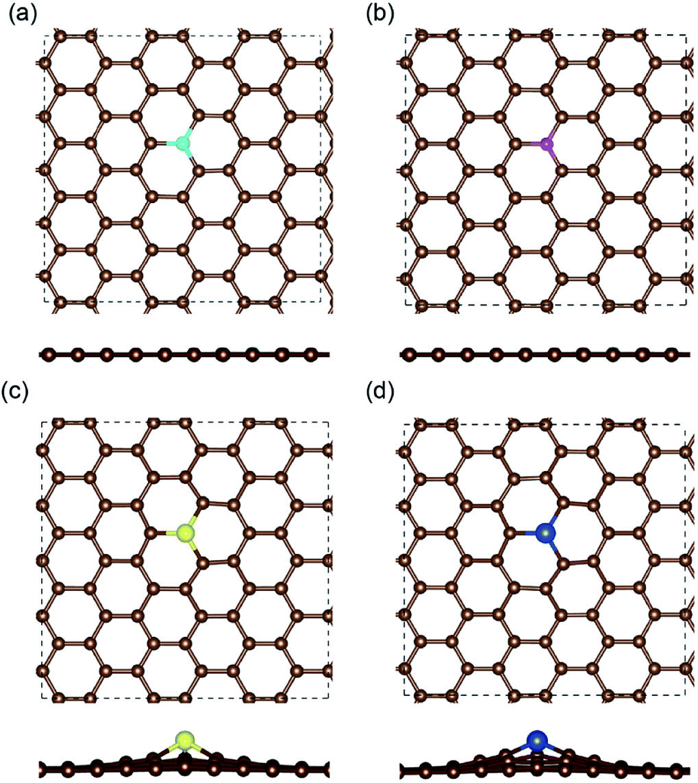 | ||
| Fig. 1 Top- and side-view of the optimized doped graphene structures, showing that the sulfur and silicon dopant atoms are out of the graphene plane. The brown, cyan, magenta, yellow and blue balls stand for C, B, N, S and Si atoms, respectively. The periodic boundary is plotted by the dashed black lines. | ||
After that, the adsorption position and energy of a single Li atom on the different doped graphene materials were calculated. To find the most stable adsorption position, six binding sites were considered, as shown in Fig. 2. The binding energy of a Li atom on doped graphene was calculated as
| Eb = (Edoped-G + nELi − ELi/doped-G)/n | (1) |
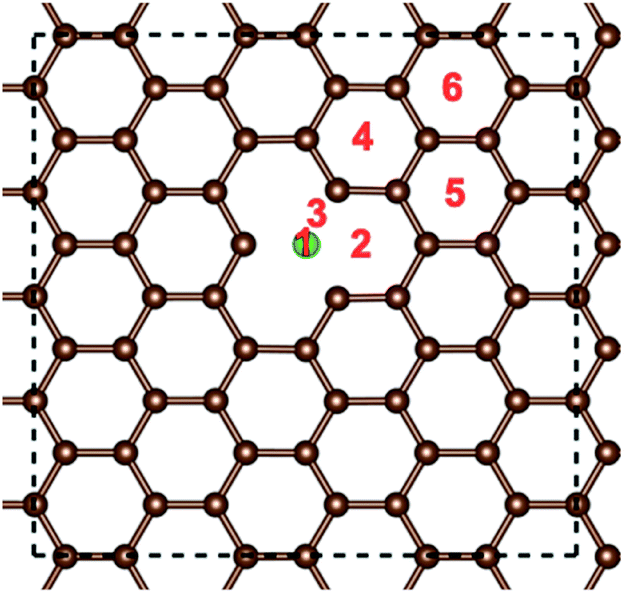 | ||
| Fig. 2 Binding positions of an Li atom on the distinct doped graphene materials. Position 1 is on the top of the dopant atom. The green ball stands for the substituted atom (B, N, S or Si), and the brown balls denote the carbon atoms. The periodic boundary is plotted by the dashed black lines. | ||
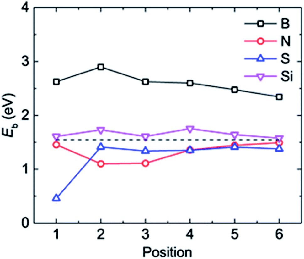 | ||
| Fig. 3 The adsorption energy Eb of a Li atom at different binding positions in the doped graphene materials. The dashed black line represents the Li binding energy on the pristine graphene monolayer. | ||
The most stable structures of Li binding on the different doped graphene materials are presented in Fig. 4. In the B-doped graphene anode, the Li atom preferred to bind at the center top of the hexagonal structure, which constitutes the substituted boron and five carbon atoms. In the N- and S-doped graphene structures, we discovered that the Li atom tended to stay on top of the hexagon with six carbon atoms, away from the doped atom. This demonstrated that the introduction of nitrogen or sulfur atoms has little effect on the adsorption of Li atoms. However, recent theoretical studies have shown that when S and N atoms are doped on graphene simultaneously, the Li adsorption energy is larger than that on B-mono-doped graphene.13 In this paper, the Eb value of Li binding on SN-dual-doped graphene was calculated to be 3.59 eV, which is larger than that of a single Li atom on B-doped graphene. Thus, in the mono-doped situation, these doped graphene anodes are not good choices to improve Li-binding energy. In the end, when a silicon atom was doped on graphene, it showed a smaller improvement in Li-binding energy than that of pristine graphene. The Li atom tended to be bound on top of the carbon atom that was bonded to the doped Si atom, as shown in Fig. 4(d).
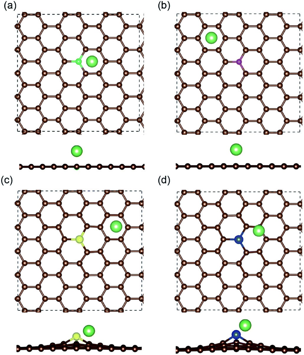 | ||
| Fig. 4 The most stable binding structures of a Li atom on the (a) B-, (b) N-, (c) S- and (d) Si-doped graphene anodes. The brown, cyan, magenta, yellow, blue and green balls stand for carbon, boron, nitrogen, sulfur, silicon and lithium atoms, respectively. The periodic boundary is plotted by the dashed black lines. | ||
3.2 Charge transfer when Li atom binds on doped graphene
To understand the adsorption behavior of Li atoms on the different doped graphene anodes, charge transfer was calculated by employing Bader charge analysis. The results are shown in Table 2, along with the electronegativity of the doped atoms. It was found that on B-, S- and Si-doped graphene, charge transfer occurred from the doped atom to the carbon atoms, indicating that the doped atoms were the donors of electrons. However, in N-doped graphene, the nitrogen atom was the acceptor of electrons from the adjacent carbon atoms. This was because the electronegativity of nitrogen (χN = 3.04) was larger than that of the carbon atoms (χC = 2.55) and consistent with the previously reported results for B- and N-doped graphene.16 After that, the Bader charge values of the doped atoms when a Li atom was bound on the doped graphene anodes were checked. It was demonstrated that the boron substitute atom gained 0.07e and sulfur lost 0.11e after Li intercalation, indicating that Li adsorption led to little charge transfer in the B and S dopants. However, there was a large charge transfer in S-doped graphene after Li intercalation, with about 1e gain for the doped silicon atom, meaning a strong interaction between the Li and Si atoms, which is consistent with a previous study.27 For the doped nitrogen atom, the charge transfer was nearly the same before and after the insertion of a Li atom. This is maybe due to the fact that the Li binding position in N-doped graphene is away from the N atom, and the Li atom mainly interacts with carbon atoms. The electronegativity of a lithium atom is χLi = 0.98, which is much small than those of carbon and the four different doped atoms. Thus, we found that the Li atom is the electron donor and most of the valence electrons move to doped graphene during the lithiation process.| Doped atom | Electronegativity | Bader charge transfer without Li | Bader charge transfer with Li |
|---|---|---|---|
| B | 2.04 | −1.85e | −1.78e |
| N | 3.04 | 1.12e | 1.14e |
| S | 2.58 | −0.29e | −0.40e |
| Si | 1.90 | −2.57e | −1.61e |
In addition, the charge density difference Δρ between the doped graphene anodes and Li atom were calculated and plotted, as seen in Fig. 5, to clarify the electronic gain and loss in space. It is defined by subtracting the charge densities of an isolated Li atom and doped graphene from that of doped graphene with Li intercalation, as shown below.
| Δρ = ρ[Li/doped graphene] − ρ[Li] − ρ[doped graphene] | (2) |
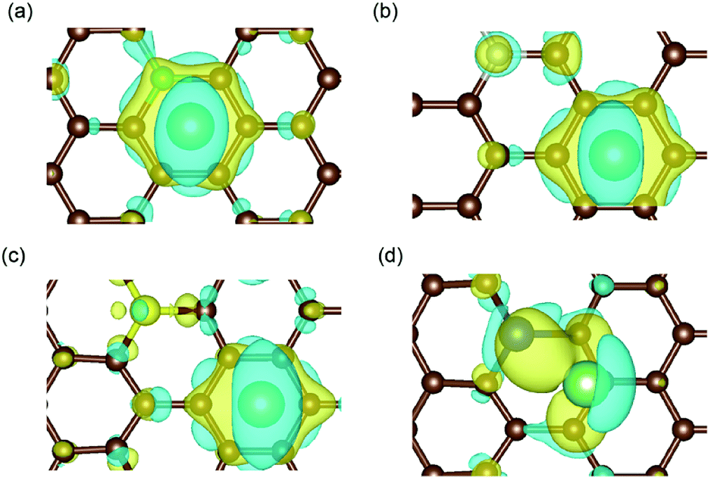 | ||
| Fig. 5 Charge density difference in (a) B-, (b) N-, (c) S- and (d) Si-doped graphene with Li atom intercalation, with the same iso-surface level of 0.0021. The space enclosed by the yellow and blue iso-surfaces are the electron-gaining and losing regions, respectively.42 The brown, cyan, magenta, yellow, blue and green balls stand for carbon, boron, nitrogen, sulfur, silicon and lithium atoms, respectively. | ||
The results in Fig. 5(a) and (d) obviously illustrate the charge transfer between the boron/silicon dopant and the inserted Li atom, which indicate the interactions between them. However, in N-/S-doped graphene, the Li atom mainly interacted with the hexagonal carbon atoms of graphene. Combined with the adsorption energy results, it could be concluded that the doped atoms in graphene that interact with Li atoms (such as boron and silicon) enhance the adsorption energy and aid the anode materials remain stable during the lithiation process.
3.3 Effect of strain on the adsorption of Li atom on doped graphene
As mentioned above, large expansions occur in bulk anode materials during the lithiation process, which impacts the electrochemical and safety performance of LIBs, especially the cycling life. As coating materials, graphene and its derivatives also undergo stretching when Li atoms are intercalated. Therefore, the uniaxial tensions of the different doped graphene anodes in the zigzag and armchair directions were calculated. For comparison, pristine graphene, as well as defective graphene with a single vacancy (SV), were considered. Our calculation results showed that the yield strengths of pristine graphene in the zigzag and armchair directions were ∼100 GPa and 110 GPa, respectively. This is in agreement with a previous first-principles study.38 The tensile stress–strain curves of the different dope graphene anodes are plotted in Fig. 6. They demonstrated that the substituted atom significantly reduced the tensile strength of the graphene monolayer. Among the substitute atoms, the B-doped graphene monolayer showed the highest yield strengths of 94.6 GPa and 97 GPa. In the molecular dynamic simulations, it was also found that the B dopant atom slightly reduced the tensile strength of graphene from 160 GPa to 145 GPa, and the plasticity of B-doped graphene shifted from ductile to brittle with increasing boron concentration.39 In the meantime, we found that the tensile stress–strain curves of S-doped graphene and graphene with the SV defect were approximately the same, which indicated that the interactions between the doped sulfur atom and the carbon atoms in graphene were extremely weak. The N and Si atoms did not only reduce the tensile strength of the graphene anode,40 but also failed to enhance Li atom adsorption. Therefore, they are not good candidates for the modification of pristine graphene into better anode materials. | ||
| Fig. 6 The uniaxial tensile stress–strain curves of the different doped graphene materials, pristine graphene and graphene with single vacancy (SV) in the (a) zigzag and (b) armchair directions. | ||
In a previous study on pristine graphene, it was illustrated that tensile strain was able to enhance the Li binding kinetics.41 To find the effect of strain on the performance of the doped graphene anodes, the Li binding energies Eb under biaxial strain were calculated, as shown in Fig. 7. The maximum strain value was set to 10% to ensure no yielding of doped graphene anodes. The results demonstrated that for boron, nitrogen and sulfur doping, the adsorption energy grew monotonously with the stretching of the doped graphene monolayer. In the meantime, when silicon was substituted in pristine graphene, the value of Eb dropped at first and then, linearly increased after the strain reached 2% owing to the fact that biaxial stretching results in the geometric structural variation of Si-doped graphene, subsequently changing the stable Li binding position. It was found that without strain, the stable Li binding site was on top of the Si atom. With increasing strain, the substituted Si atom entered the graphene plane and the Li atom gradually moved to the hollow site with the dopant, as shown in Fig. 8. In addition, we also explored the effect of strain on the adsorption behavior of Li on SN-dual-doped graphene due to its high binding energy. The result indicated that biaxial tensile strain reduced the Li binding kinetics. This difference was because the Li atom mainly interacts with the dopant atoms in SN-dual-doped graphene, while in mono-doped-graphene, there are interactions between the Li and carbon atoms. At the same time, the mechanical property of SN-dual-doped graphene decreased compared with that of mono-doped graphene, and the material fractured when 5% biaxial strain was applied. These computational results illustrate that tensile strain contributes to the binding of Li atoms on both pristine and mono-doped graphene anodes.
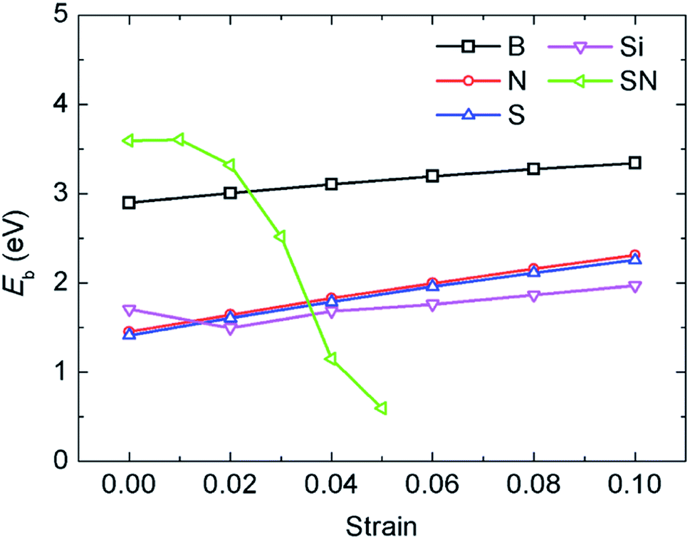 | ||
| Fig. 7 The influence of biaxial tensile strain on the adsorption energy of Li atoms in the different mono-doped graphene and SN-dual-doped graphene anodes. | ||
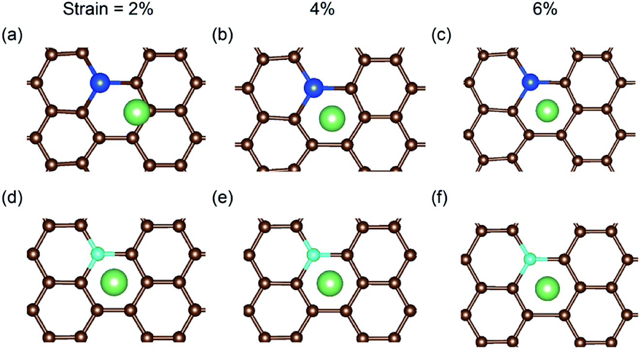 | ||
| Fig. 8 The local relaxed structures of Li adsorbed on Si-doped graphene with (a) 2%, (b) 4% and (c) 6% biaxial tensile strain. For comparison, the relaxed structures of B-doped graphene with (d) 2%, (e) 4% and (f) 6% strain are shown. | ||
4. Conclusion
In summary, the adsorption of a Li atom on various doped graphene anode materials and the effect of strain on the binding energy were investigated. The results demonstrate that B-doped graphene is more energetically preferable for Li atom binding than the other tested doped graphene materials and pristine graphene. Based on the charge transfer analysis, the dopant atoms that can interact with the Li atom enhance the adsorption energy and make the graphene anode material more stable during lithiation. However, the substituted boron atom led to a little drop in the mechanical tensile strength of the graphene monolayer both in the zigzag and armchair directions. During the charging processes, the tensile strain in the doped graphene anode enhances the interactions between the Li atom and the doped graphene monolayer due to the rise in binding energy. Base on the first-principles calculations performed in this work, it is suggested that doped graphene with boron atoms can be employed in LIBs. In addition, the aggregation and diffusion of Li atoms on the distinct doped graphene materials, as well as the effect of the concentration of the doped atom, should be studied in the future.Conflicts of interest
There are no conflicts to declare.Acknowledgements
The computations were performed on the Explorer 100 cluster system at Tsinghua Nation Laboratory for Information Science and Technology. The authors are grateful for the discussion with Prof. Zhiping Xu at Tsinghua University.References
- J. Lu, Z. Chen, F. Pan, Y. Cui and K. Amine, Electrochem. Energy Rev., 2018, 1, 35–53 CrossRef CAS.
- B. Liu, Y. Jia, J. Li, S. Yin, C. Yuan, Z. Hu, L. Wang, Y. Li and J. Xu, J. Mater. Chem. A, 2018, 6, 21475–21484 RSC.
- B. Liu, Y. Jia, C. Yuan, L. Wang, X. Gao, S. Yin and J. Xu, Energy Storage Materials, 2020, 24, 85–112 CrossRef.
- G. Wang, X. Shen, J. Yao and J. Park, Carbon, 2009, 47, 2049–2053 CrossRef CAS.
- E. Yoo, J. Kim, E. Hosono, H.-s. Zhou, T. Kudo and I. Honma, Nano Lett., 2008, 8, 2277–2282 CrossRef CAS PubMed.
- H. Jung, M. Park, Y.-G. Yoon, G.-B. Kim and S.-K. Joo, J. Power Sources, 2003, 115, 346–351 CrossRef CAS.
- W. Zhang, J. Power Sources, 2011, 196, 13–24 CrossRef CAS.
- P. Poizot, S. Laruelle, S. Grugeon, L. Dupont and J. M. Tarascon, Nature, 2000, 407, 496–499 CrossRef CAS PubMed.
- C. Lee, X. Wei, J. W. Kysar and J. Hone, Science, 2008, 321, 385–388 CrossRef CAS PubMed.
- J.-H. Chen, C. Jang, S. Xiao, M. Ishigami and M. S. Fuhrer, Nat. Nanotechnol., 2008, 3, 206–209 CrossRef CAS PubMed.
- A. A. Balandin, S. Ghosh, W. Bao, I. Calizo, D. Teweldebrhan, F. Miao and C. N. Lau, Nano Lett., 2008, 8, 902–907 CrossRef CAS PubMed.
- Z.-S. Wu, W. Ren, L. Xu, F. Li and H.-M. Cheng, ACS Nano, 2011, 5, 5463–5471 CrossRef CAS PubMed.
- P. A. Denis, Chem. Phys. Lett., 2017, 672, 70–79 CrossRef CAS.
- L.-J. Zhou, Z. F. Hou and L.-M. Wu, J. Phys. Chem. C, 2012, 116, 21780–21787 CrossRef CAS.
- L.-J. Zhou, Z. F. Hou, L.-M. Wu and Y.-F. Zhang, J. Phys. Chem. C, 2014, 118, 28055–28062 CrossRef CAS.
- R. P. Hardikar, D. Das, S. S. Han, K.-R. Lee and A. K. Singh, Phys. Chem. Chem. Phys., 2014, 16, 16502–16508 RSC.
- X. Wang, Z. Zeng, H. Ahn and G. Wang, Appl. Phys. Lett., 2009, 95, 183103 CrossRef.
- C. Ma, X. Shao and D. Cao, J. Mater. Chem., 2012, 22, 8911–8915 RSC.
- P. A. Denis, Chem. Phys. Lett., 2010, 492, 251–257 CrossRef CAS.
- Y. S. Yun, V.-D. Le, H. Kim, S.-J. Chang, S. J. Baek, S. Park, B. H. Kim, Y.-H. Kim, K. Kang and H.-J. Jin, J. Power Sources, 2014, 262, 79–85 CrossRef CAS.
- M. Rafique, Y. Shuai and N. Hussain, Phys. E Low-dimens. Syst. Nanostruct., 2018, 95, 94–101 CrossRef CAS.
- H. Wang, M. Wu, X. Lei, Z. Tian, B. Xu, K. Huang and C. Ouyang, Nano Energy, 2018, 49, 67–76 CrossRef CAS.
- M. Shahid, N. Yesibolati, M. C. Reuter, F. M. Ross and H. N. Alshareef, J. Power Sources, 2014, 263, 239–245 CrossRef CAS.
- X. Zhou, L.-J. Wan and Y.-G. Guo, Adv. Mater., 2013, 25, 2152–2157 CrossRef CAS PubMed.
- H. Tang, J. Zhang, Y. J. Zhang, Q. Q. Xiong, Y. Y. Tong, Y. Li, X. L. Wang, C. D. Gu and J. P. Tu, J. Power Sources, 2015, 286, 431–437 CrossRef CAS.
- B. Fang, J. Li, N. Zhao, C. Shi, L. Ma, C. He, F. He and E. Liu, Appl. Surf. Sci., 2017, 425, 811–822 CrossRef CAS.
- C. Chang, X. Li, Z. Xu and H. Gao, Acta Mech. Solida Sin., 2017, 30, 254–262 CrossRef.
- G. Kresse and J. Furthmüller, Comput. Mater. Sci., 1996, 6, 15–50 CrossRef CAS.
- G. Kresse and J. Furthmüller, Phys. Rev. B: Condens. Matter Mater. Phys., 1996, 54, 11169–11186 CrossRef CAS PubMed.
- G. Kresse and D. Joubert, Phys. Rev. B: Condens. Matter Mater. Phys., 1999, 59, 1758–1775 CrossRef CAS.
- J. P. Perdew, K. Burke and M. Ernzerhof, Phys. Rev. Lett., 1996, 77, 3865–3868 CrossRef CAS PubMed.
- C. Lee, X. Wei, J. W. Kysar and J. Hone, Science, 2008, 321, 385 CrossRef CAS PubMed.
- H. R. Jiang, T. S. Zhao, L. Shi, P. Tan and L. An, J. Phys. Chem. C, 2016, 120, 6612–6618 CrossRef CAS.
- J. Dai, J. Yuan and P. Giannozzi, Appl. Phys. Lett., 2009, 95, 232105 CrossRef.
- A. M. Garay-Tapia, A. H. Romero and V. Barone, J. Chem. Theory Comput., 2012, 8, 1064–1071 CrossRef CAS PubMed.
- H. J. Hwang, J. Koo, M. Park, N. Park, Y. Kwon and H. Lee, J. Phys. Chem. C, 2013, 117, 6919–6923 CrossRef CAS.
- B. J. Landi, M. J. Ganter, C. D. Cress, R. A. DiLeo and R. P. Raffaelle, Energy Environ. Sci., 2009, 2, 638–654 RSC.
- Z. Xu and K. Xue, Nanotechnology, 2009, 21, 045704 CrossRef PubMed.
- B. Mortazavi and S. Ahzi, Solid State Commun., 2012, 152, 1503–1507 CrossRef CAS.
- B. Mortazavi, S. Ahzi, V. Toniazzo and Y. Rémond, Phys. Lett. A, 2012, 376, 1146–1153 CrossRef CAS.
- F. Hao and X. Chen, Mater. Res. Express, 2015, 2, 105016 CrossRef.
- K. Momma and F. Izumi, J. Appl. Crystallogr., 2008, 41, 653–658 CrossRef CAS.
Footnote |
| † Electronic supplementary information (ESI) available. See DOI: 10.1039/d0ra01086c |
| This journal is © The Royal Society of Chemistry 2020 |