 Open Access Article
Hierarchical assembly of ZnO nanowire trunks decorated with ZnO nanosheets for lithium ion battery anodes†
Dongheun Kim‡
,
Sun Hae Ra Shin‡,
Yeonhoo Kim,
Kenneth Crossley ,
Yerim Kim,
Hyungkyu Han§
 * and
Jinkyoung Yoo
 *
*
Center for Integrated Nanotechnologies, Los Alamos National Laboratory, Los Alamos, NM 87545, USA. E-mail: hhan@pnnl.gov; jyoo@lanl.gov
First published on 3rd April 2020
Abstract
Hierarchical architectures composed of nanomaterials in different forms are essential to improve the performance of lithium-ion battery (LIB) anodes. Here, we systematically studied the effects of hierarchical ZnO nanostructures on the electrochemical performance of LIBs. ZnO nanowire (NW) trunks were decorated with ZnO NWs or ZnO nanosheets (NSs) by successive hydrothermal synthesis to create hierarchical three-dimensional nanostructures. The branched ZnO NSs on the ZnO NW trunk exhibited a two-fold higher specific gravimetric capacity compared to ZnO NWs and branched ZnO NWs on ZnO NW trunks after 100 cycles of charging–discharging at 0.2C (197.4 mA g−1). The improvement in battery anode performance is attributable to the increased interfacial area between the electrodes and electrolyte, and the void space of the branched NSs that facilitates lithium ion transport and volume changes during cycling.
1. Introduction
The development of novel materials for lithium-ion batteries (LIBs) has been motivated by the increasing demand for power sources with high energy density and high power density for portable electronic devices and electric vehicles.1,2 Nano-sized transition-metal oxides have received much attention as potential anode materials for LIBs, given the ease of large-scale fabrication and their high theoretical capacity.3 Zinc oxide (ZnO), in particular, is a promising LIB anode material due to its non-toxicity, facile and scalable synthesis, and a theoretical capacity of 978 mA h g−1, which is three times higher than that of graphite.4 However, the large volume change (∼220%) associated with lithium–zinc alloying and dealloying, and the conversion reaction of Zn/ZnO, causes structural degradation of the material and loss of contact from the current collector, ultimately limiting their cycle life of these materials.5 To overcome these challenges, one-dimensional (1D) ZnO nanostructures have been applied as LIB anodes and significantly improved the results.6 Additionally, 1D nanostructures such as nanowires (NWs), nanorods, and nanotubes are expected to increase the rate capability, and reduce the lithium ion diffusion length, while providing a direct electron pathway from the active material to the current collector.5 Moreover, 1D nanostructures grown directly on current collectors have advantages over their corresponding bulk materials because each individual 1D nanostructure remains in electrical contact despite recurring large volume fluctuations as a result of alloying and dealloying processes. Nevertheless, the advantages of 1D nanostructures for LIB electrodes have not been fully utilized. Given the low number density of 1D nanostructures in a projected area, less interfacial area between the electrodes and electrolyte when using these nanostructures has prompted the search for new material configurations.7Enhancement of the surface area of LIB electrodes based on 1D nanostructures can be achieved by manufacturing three-dimensional (3D) architectures. Decorating the surfaces of 1D nanostructures with other nanomaterials, such as NWs or nanosheets (NSs), is a facile route to create 3D nanoarchitectures.8–10 Moreover, morphologies of nanomaterials decorating 1D nanostructures result in different structural stability and lithium ion transport in the 3D architectures.
Here we report 3D hierarchical ZnO nanostructures with enlarged surface areas as anode materials for LIBs. ZnO NWs were decorated with short ZnO NWs or ZnO NSs by successive hydrothermal synthesis processes to manufacture hierarchical 3D nanostructures. The branched 3D architecture allows for a larger lithium ion flux due to increases in the void space and interfacial area between the electrodes and electrolyte relative to the 1D architecture alone. The branched ZnO nanostructured electrodes exhibited a significant improvement in capacity and rate capability compared to ZnO NW electrodes. The enhancement extent of electrochemical performances of 3D hierarchical ZnO nanostructures upon morphology was studied.
2. Experimental
2.1 Synthesis of 3D hierarchical ZnO nanostructures
ZnO NW trunks were prepared by a hydrothermal synthesis described in detail in a previous study.11 Briefly, ZnO nanoparticles (NPs) were deposited onto a stainless steel disk by spin coating of the NP suspension to form seeds for ZnO NWs growth. The ZnO NPs-decorated substrates were immersed in a nutrient solution [‘1’; 25 mM zinc nitrate hexahydrate (Zn(NO3)2·6H2O), 25 mM hexamethylenetetramine (HMTA, C6H12N4), 5 mM polyethylenimine (PEI), and 0.2 M ammonium hydroxide] at 95 °C for 7 h. After NW synthesis, the ZnO NW samples were thoroughly rinsed with deionized water to remove the residue (HTMA, PEI) and dried in air. The ZnO NW branches on the ZnO NW trunks (denoted as ZnO NWs-NWs) were grown by decoration of the ZnO NW surfaces with ZnO NPs and subsequent hydrothermal synthesis of ZnO NWs in a fresh nutrient solution (‘1’) at 100 °C for 4 h. The growth of ZnO NSs on the surfaces of ZnO NW trunks (denoted as ZnO NWs-NSs) was achieved by immersing the ZnO NW trunks in nutrient solution ‘2’ [25 mM zinc nitrate hexahydrate, 200 mM HMTA, and 0.2 mM sodium citrate (Na3C6H5O7·2H2O)] at 100 °C for 4 h without the addition of seeds.2.2 Characterization
The 3D ZnO nanostructures were characterized using a scanning electron microscopy (SEM) and transmission electron microscopy (TEM). CR2032-type half coin cells were assembled to characterize the electrochemical performance of LIB anodes based on ZnO NWs-NWs and ZnO NWs-NSs. Lithium metal foil was used as a counter electrode, and 1 M lithium hexafluorophosphate (LiPF6) in a mixture of ethyl carbonate and dimethyl carbonate (EC/DMC, 1![[thin space (1/6-em)]](https://www.rsc.org/images/entities/char_2009.gif) :
:![[thin space (1/6-em)]](https://www.rsc.org/images/entities/char_2009.gif) 1) was used as the electrolyte. Battery anode performance was characterized using a potentiostat (VMP-3; Bio-Logic).
1) was used as the electrolyte. Battery anode performance was characterized using a potentiostat (VMP-3; Bio-Logic).
3. Results and discussion
3.1 Preparation of hierarchical ZnO nanostructures
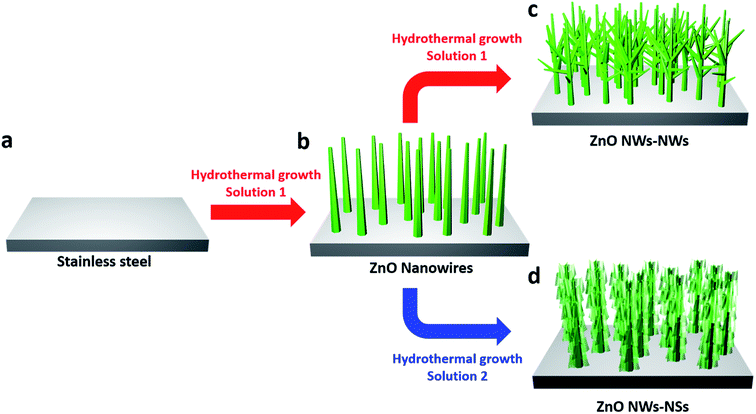
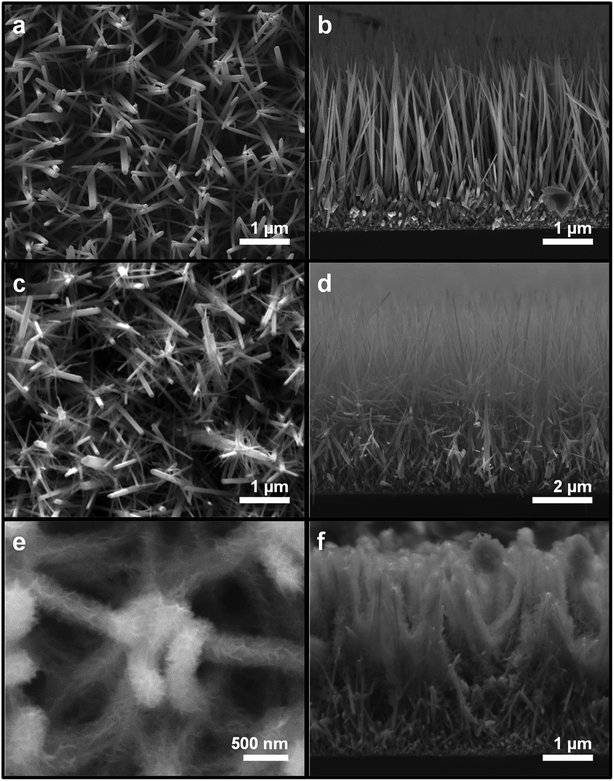
The 3D hierarchical ZnO nanostructures were synthesized in a controlled manner by successive hydrothermal growth. Fig. 1 illustrates the synthesis procedures of ZnO NW trunks, ZnO NWs-NWs, and ZnO NWs-NSs [Fig. 1b–d, respectively]. Fig. 2(a) and (b) show the SEM images of vertically aligned and closely packed ZnO NW trunks with smooth surfaces and hexagonal cross-sections. The typical length of a ZnO NW trunk was ∼5 μm, and the NW diameter ranged from 70 to 150 nm. Fig. 2(c) and (d) show the formation of ZnO NW branches on the surfaces of the ZnO NW trunks. The typical length of branched ZnO NWs was ∼1.2 μm, and the diameter was in the range of 20–50 nm, much smaller than the ZnO NW trunk diameter due to the shorter growth time of 4 h (vs. 7 h for the NW trunks). The tree-like 3D structures achieved via growth of branch NWs on NW trunks provided a significantly larger surface area for the entire architecture, and additional pathways for Li+ intercalation, compared to 1D structures. Furthermore, the space between ZnO branch NWs can reduce the self-agglomeration of ZnO NW trunks.Two-dimensional (2D) branches were constructed on the ZnO NW trunks to investigate the morphological effect on LIB anode performances of 3D nanostructures. We note that the concentration of sodium citrate, the capping agent, affects the morphology of 2D ZnO nanostructures by blocking the growth of ZnO along the [0001] direction in favor of the disk shape of 2D ZnO nanostructures.12 For 0.05 mM and 0.1 mM of sodium citrate, the formation of hexagonal ZnO nanodisks was dominant and the thickness of hexagonal ZnO nanodisks was inversely proportional to the concentration of sodium citrate, as shown in Fig. S1a (50 nm for 0.05 mM) and Fig. S1b (10 nm for 0.1 mM) in the ESI.† However, for higher sodium citrate concentration (0.2 mM), which is the experimental condition for the branched ZnO nanostructures, ZnO NSs became the dominant 2D nanostructures (ESI, Fig. S2†).
Fig. 2(e) and (f) show the growth of ZnO NSs (thickness: ∼15 nm) on the ZnO NW trunk surface. The surfaces of as-prepared ZnO NWs (Fig. 2b) were smooth; however, the surfaces of ZnO NWs-NSs were downy and the ZnO NWs-NSs form a network connected with a large number of ZnO NSs. These NS branches enlarged the surface area and acted as a bridge to link the adjacent NW trunks, creating a 3D network configuration with enhanced mechanical robustness.
3.2 Electrochemical characteristics of hierarchical ZnO nanostructures
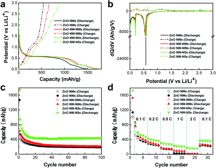
The effect of hierarchical architectures on the electrochemical characteristics of ZnO nanostructures was investigated. Fig. 3a shows the voltage profiles of the first cycle for the three types of ZnO nanostructured electrodes in the range of 0.01–3 V versus Li/Li+ at a rate of 0.05C (49.35 mA g−1). The ZnO NWs-NSs and ZnO NWs-NWs exhibited similar initial discharge capacities of 1760 mA h g−1 and 1752 mA h g−1, respectively, which were higher than that of the ZnO NWs (1473 mA h g−1). The initial discharge capacity of the ZnO nanostructures was higher than the theoretical capacity of 987 mA h g−1, which can be attributed to extra lithium consumption during formation of the solid electrolyte interphase (SEI) layer.13,14 The ZnO NWs-NSs delivered a higher initial charge capacity, of 878 mA h g−1, than those of the ZnO NWs (534 mA h g−1) and of the ZnO NWs-NWs (657 mA h g−1). The significant improvement of ZnO NWs-NSs in charge capacity compared to that of ZnO NWs is due to the large electrode/electrolyte interfacial area, short Li ion diffusion length, direct electron pathway, and strain accommodation.5 The ZnO NWs, ZnO NWs-NWs, and ZnO NWs-NSs exhibited initial coulombic efficiencies of 36.8%, 37.5%, and 49.9%, respectively. The low coulombic efficiency in the initial stage is a characteristic feature of the metal oxide anode materials and can be ascribed to the irreversible process of Li2O formation and the formation of the SEI layer, as indicated by the long potential slope at 0.4–0.5 V.6,14 The differential capacity versus potential (dQ/dV vs. V) plots for the first cycle of ZnO NWs, ZnO NWs-NWs, and ZnO NWs-NSs are shown in Fig. 3b. In the discharging curve, the strong feature at 0.6 V corresponds to the reduction of ZnO (ZnO + 2Li → Zn + Li2O).15 A peak at 0.15 V represents the decomposition of the electrolyte, SEI layer growth, and lithium–zinc alloy formation (Li + Zn → LiZn).16 Whereas, in the discharge curve, the LiZn at potential reached 0.25 V and at 0.44 V transformed to LiZn4. The weak peaks located at 0.5–0.8 V are attributed to a multi-step Li–Zn dealloying process (LiZn, Li2Zn3, LiZn2 and Li2Zn5).4,14 At a potential of 1.0 V, the LiZn4 phase transformed to a Zn phase.17 In addition, the broad peak located at 1.3 V is related to the decomposition of Li2O.18 Another peak at 2.5 V appeared for the reaction between Zn and Li2O.Fig. 3c shows the cycle performances of the three types of ZnO nanostructured electrodes at a rate of 0.2C (197.4 mA g−1). Although both the ZnO NWs-NWs and ZnO NWs-NSs exhibited similar specific capacity during the first cycle, the specific capacity of ZnO NWs-NSs was higher than those of the ZnO NWs and of the ZnO NWs-NWs in the following cycles. After 100 cycles the ZnO NWs-NSs showed a reversible capacity of 440 mA h g−1 at a rate of 0.2C (197.4 mA g−1), which is two-fold higher than those of the ZnO NWs (188 mA h g−1) and of the ZnO NWs-NWs (204 mA h g−1).
The rate capability of the three types of ZnO nanostructured electrodes was evaluated at various current rates, as shown in Fig. 3d. The ZnO NWs-NWs exhibited enhanced rate performance compared to the ZnO NWs at all current rates. The ZnO NW-NSs showed a much improved rate capability compared to ZnO NWs-NWs and ZnO NWs; they exhibited 17.4- and 20.1-times larger capacity than ZnO NWs-NWs and ZnO NWs, respectively, at a current density of 2C (1974 mA g−1).
The superior electrochemical performance of the hierarchical assembly of ZnO nanostructures on ZnO NW trunks compared to 1D ZnO nanostructures can be attributed to the synergistic effects of the ZnO NW trunk combined with ZnO branches, and can be understood based on the following considerations. First, the highly ordered 1D geometry of the ZnO NW trunk without a binder is electrically connected to the current collector in a way that can provide short and straight electron pathways, allowing for efficient electron transport in the electrode.19 Second, the enlarged surface area of branched ZnO nanostructured electrodes provides sufficient space for lithium storage, including lithium–zinc alloy (LiZn, Li2Zn3, LiZn2, and Li2Zn5) and Li2O.
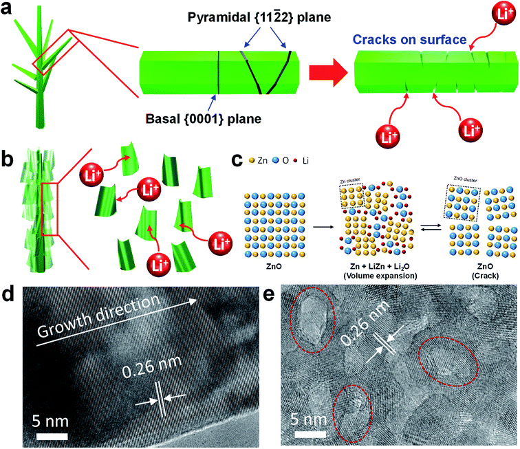
Importantly, the 3D network structure of ZnO NWs-NSs offers the additional advantage of mechanical robustness over ZnO NWs-NWs. As a result of the lithiation process, large tensile stresses applied to the ZnO NWs can lead to the generation and propagation of nano-cracks along the {0001} or {11![[2 with combining macron]](https://www.rsc.org/images/entities/char_0032_0304.gif) 2} cleavage planes of ZnO NWs (Fig. 4a).5 In contrast, the network structure of ZnO NSs was retained due to its mechanical integrity during lithiation.20,21 As revealed by high resolution TEM, compared to the single crystalline ZnO NW branches which were grown along [001] direction (Fig. 4d), the ZnO NS branches create a highly porous network that yields abundant active sites due to the enhanced surface area for Li ion insertion, as well as sufficient void spaces (dotted red circle line in Fig. 4e) to act as shorter diffusion paths for Li ions, giving rise to high capacities.
2} cleavage planes of ZnO NWs (Fig. 4a).5 In contrast, the network structure of ZnO NSs was retained due to its mechanical integrity during lithiation.20,21 As revealed by high resolution TEM, compared to the single crystalline ZnO NW branches which were grown along [001] direction (Fig. 4d), the ZnO NS branches create a highly porous network that yields abundant active sites due to the enhanced surface area for Li ion insertion, as well as sufficient void spaces (dotted red circle line in Fig. 4e) to act as shorter diffusion paths for Li ions, giving rise to high capacities.
To check the morphology of the ZnO nanostructures after cycling, the coin cells were disassembled after 100 cycles, at a rate of 0.2C (197.4 mA g−1) in the discharged state. The current collectors were soaked in acetonitrile overnight and rinsed with isopropanol. While the smooth surfaces of ZnO NWs and ZnO NWs-NWs became rough after 100 cycles, the connected structures of ZnO NWs-NSs were maintained, as confirmed by SEM (Fig. 5).
 | ||
| Fig. 5 SEM images of ZnO nanostructured electrodes after 100 cycles. (a) ZnO NW, (b) ZnO NWs-NWs, and (c) ZnO NWs-NSs. | ||
4. Conclusion
In summary, 3D hierarchical ZnO nanostructures, ZnO NWs-NWs and ZnO NWs-NSs, were synthesized through successive hydrothermal growth. The branched architecture offers the advantages over the 1D architecture, i.e., a large surface area and enough void space. The fabricated nanostructures were employed directly as anodes for LIBs. The electrodes exhibited excellent lithium-storage performance, including a high specific capacity and cycle performance. ZnO NWs-NSs showed a reversible capacity of 440 mA h g−1 at a rate of 0.2C after 100 cycles, which is two-fold that of ZnO NWs and ZnO NWs-NWs. We confirmed that the porous network structure of ZnO NWs-NSs was maintained after charging–discharging cycles. Our results indicate that hierarchical ZnO NWs-NSs represent a promising anode material for high-performance LIBs.Conflicts of interest
There are no conflicts to declare.Acknowledgements
This work was performed in part at CINT, a U.S. Department of Energy, Office of Basic Energy Sciences User Facility at Los Alamos National Laboratory (Contract DE-AC52-06NA25396), and partly funded by the Laboratory Directed Research and Development Program at LANL.References
- L. Croguennec and M. R. Palacin, J. Am. Chem. Soc., 2015, 137, 3140–3156 CrossRef CAS.
- J. B. Goodenough and K. S. Park, J. Am. Chem. Soc., 2013, 135, 1167–1176 CrossRef CAS.
- J. Jiang, Y. Y. Li, J. P. Liu, X. T. Huang, C. Z. Yuan and X. W. Lou, Adv. Mater., 2012, 24, 5166–5180 CrossRef CAS PubMed.
- H. B. Wang, Q. M. Pan, Y. X. Cheng, J. W. Zhao and G. P. Yin, Electrochim. Acta, 2009, 54, 2851–2855 CrossRef CAS.
- A. Kushima, X. H. Liu, G. Zhu, Z. L. Wang, J. Y. Huang and J. Li, Nano Lett., 2011, 11, 4535–4541 CrossRef CAS PubMed.
- X. H. Huang, J. B. Wu, Y. Lin and R. Q. Guo, Int. J. Electrochem. Sci., 2012, 7, 6611–6621 CAS.
- L. Huang, Q. L. Wei, R. M. Sun and L. Q. Mai, Frontiers in Energy Research, 2014, 2, 43 CrossRef.
- H. C. Song, H. X. Wang, Z. X. Lin, L. W. Yu, X. F. Jiang, Z. W. Yu, J. Xu, L. J. Pan, M. B. Zheng, Y. Shi and K. J. Chen, Nano Energy, 2016, 19, 511–521 CrossRef CAS.
- H. Wu, M. Xu, Y. C. Wang and G. F. Zheng, Nano Res., 2013, 6, 167–173 CrossRef CAS.
- H. X. Chen, Q. B. Zhang, J. X. Wang, D. G. Xu, X. H. Li, Y. Yang and K. L. Zhang, J. Mater. Chem. A, 2014, 2, 8483–8490 RSC.
- S. H. Ko, D. Lee, H. W. Kang, K. H. Nam, J. Y. Yeo, S. J. Hong, C. P. Grigoropoulos and H. J. Sung, Nano Lett., 2011, 11, 666–671 CrossRef CAS PubMed.
- H. N. Chen, Z. H. Wei, K. Y. Yan, Y. Bai, Z. L. Zhu, T. Zhang and S. H. Yang, Small, 2014, 10, 4760–4769 CrossRef CAS PubMed.
- C. Q. Zhang, J. P. Tu, Y. F. Yuan, X. H. Huang, X. T. Chen and F. Mao, J. Electrochem. Soc., 2007, 154, A65–A69 CrossRef CAS.
- J. F. Yan, G. Wang, H. Wang, Z. Y. Zhang, X. F. Ruan, W. Zhao, J. N. Yun and M. Z. Xu, J. Nanopart. Res., 2015, 17, 52 CrossRef.
- X. H. Huang, X. H. Xia, Y. F. Yuan and F. Zhou, Electrochim. Acta, 2011, 56, 4960–4965 CrossRef CAS.
- F. Li, L. L. Yang, G. Xu, X. Q. Huang, X. Yang, X. Wei, Z. H. Ren, G. Shen and G. R. Han, J. Alloys Compd., 2013, 577, 663–668 CrossRef CAS.
- M. G. Park, G. K. Sung, N. E. Sung, J. H. Kim and C. M. Park, J. Power Sources, 2016, 328, 607–614 CrossRef CAS.
- F. Belliard and J. T. S. Irvine, J. Power Sources, 2001, 97–8, 219–222 CrossRef.
- H. Han, T. Song, E. K. Lee, A. Devadoss, Y. Jeon, J. Ha, Y. C. Chung, Y. M. Choi, Y. G. Jung and U. Paik, ACS Nano, 2012, 6, 8308–8315 CrossRef CAS PubMed.
- R. J. Zou, Z. Y. Zhang, M. F. Yuen, M. L. Sun, J. Q. Hu, C. S. Lee and W. J. Zhang, NPG Asia Mater., 2015, 7, e195 CrossRef CAS.
- M. Zheng, D. Qiu, B. Zhao, L. Ma, X. Wang, Z. Lin, L. Pan, Y. Zheng and Y. Shi, RSC Adv., 2013, 3, 699–703 RSC.
Footnotes |
| † Electronic supplementary information (ESI) available. See DOI: 10.1039/d0ra00372g |
| ‡ These authors contributed equally to this work. |
| § Present address: Energy and Environment Directorate, Pacific Northwest National Laboratory, Richland, WA, 99354, USA. |
| This journal is © The Royal Society of Chemistry 2020 |


