 Open Access Article
A bifunctional CoP/N-doped porous carbon composite derived from a single source precursor for bisphenol A removal†
Wenhua Tong,
Yi Xie,
Wanrong Hu,
Yuanyuan Peng,
Wenbin Liu ,
Yonghong Li,
Yongkui Zhang
 and
Yabo Wang
 *
*
School of Chemical Engineering, Sichuan University, Chengdu 610065, China. E-mail: ybwang@scu.edu.cn
First published on 10th March 2020
Abstract
Transition metal phosphides are promising materials for catalysis and their synthesis procedures commonly require costly or hazardous reagents. Herein, we adopted a yeast-extracted nucleic acid as an environmentally benign non-metal source to develop bifunctional cobalt phosphide/nitrogen-doped porous carbon composites. The single source precursor, i.e., a Co2+–nucleic acid complex was formed by coordination and could be converted to cobalt phosphide/carbon by pyrolysis with the assistance of a molten salt. Material characterization confirmed the formation of a well-crystallized CoP phase, N-doped carbon and hierarchical porous structure. In situ generated reducing gases (CO, H2, PH3, etc.) from the nucleic acid were detected by thermogravimetry-mass spectrometry (TG-MS) and thermogravimetry-infrared spectroscopy (TG-IR); also, they were suggested to be responsible for the transformation of phosphate in the precursor to phosphide in CoP. When applied for model pollutant (bisphenol A, BPA) removal, the developed composite not only exhibited considerable adsorption capability, but also performed well for peroxymonosulfate activation in an advanced oxidation process (AOP). In a two-step removal procedure, 75.5% of BPA was adsorbed in 60 min and the residual 24.5% of BPA could be degraded in 2 min by AOP. Further investigations verified that sulfate radicals, hydroxyl radicals and singlet oxygen were all involved in AOP for catalytic BPA degradation. The exhausted sample could also be regenerated by a facile thermal treatment approach. In this study, we have provided a facile strategy of utilizing inherent biomass components to construct an advanced metal phosphide-containing composite, which may open a new route for the value-added conversion of biomass.
Introduction
Transition metal phosphides (TMPs) are traditional and promising hydroprocessing catalysts for quality improvement of oil fuels (desulfurization, denitrogenation, deoxygenation and dechlorination).1,2 Since TMPs combine the properties of ceramics and metals, they show high stability, good conductivity, and high strength and hardness, which have gradually aroused the attention of researchers to extend their applications. Recently, TMPs were reported to be fascinating electrocatalysts for water splitting, co-catalysts for photocatalysis, electrode materials for energy storage, catalysts for advanced oxidation processes (AOPs), etc.3–9 In particular, CoP, Co2P and Cu3P are highly efficient for organic pollutant degradation through the activation of peroxymonosulfate (PMS) or persulfate (PS) in AOPs.8–10Typically, TMPs can be synthesized by the direct phosphidation of metals by PH3, temperature-programmed reduction of metal phosphates, organic solvent-assisted solution method, solvothermal method, electrodeposition, etc.3,11 If an inorganic P precursor (NH4H2PO2, NaH2PO2, etc.) is chosen for TMP synthesis, a deoxidization process will inevitably break the P–O bond and form an M–P bond, which always requires introducing a reducing gas of H2 or in situ generated PH3. Organophosphorus precursors (trioctylphosphine, triphenylphosphine, trioctylphosphine oxide, etc.) are another choice for TMP syntheses. Although the synthesis procedure can be completed at a relatively low temperature (∼300 °C), the potential hazardous risk and high cost of the P precursor and organic solvent are great concerns. Applying white or red phosphorus for TMP synthesis will also introduce a hazardous risk. Therefore, developing a TMP synthesis strategy using a cost-effective and environmentally benign precursor is highly desirable.
Phosphorus in nature not only exists in phosphate rock, but also is a fundamental and indispensable component for all living organisms; it is present in nucleic acids, phospholipids in the cellular membrane, co-enzymes, high-energy phosphate compounds (e.g., ATP), polyphosphate granules, etc. Although the P content in cells is normally low (∼1%), P in biomass is coming to the attention of researchers. Biowaste/biomass from the fermentation industry or excess sludge in wastewater treatment plants might be potential P sources for re-utilization. P-doped biochar can be produced using the inherent P in biomass as a dopant.12–14 Recently, the microbial P-enabled synthesis of metal phosphide composites was realized by Zhang and co-authors using a two-step synthesis strategy with a hydrothermal treatment and pyrolysis process.15 Li and co-authors also adopted a similar strategy to fabricate a cobalt phosphide-containing composite for the HER using Saccharomycete yeast as the phosphorus precursor.16 According to their studies, metal oxides were formed in the hydrothermal process, which were further transformed to metal phosphides in the pyrolysis process. However, the conversion mechanism of metal oxide to metal phosphide was not systematically investigated. In the pyrolysis process of biomass, a few gases will be generated in situ under an inert atmosphere. Besides H2O and CO2, our recent study verified the generation of reducing gases CO, CH4, and PH3, which helped the conversion of cobalt phosphate to Co2P.9 Therefore, a P-containing biomass could be a promising candidate for TMP synthesis with the advantages of an environmentally benign and low-cost P precursor and no need to introduce an extra reducing reagent. Moreover, a biomass-induced biochar could also function as an electron conducting medium, adsorbent, and support for TMPs, which may further improve the performance of a TMP composite.
In our previous study, a hydrothermal treatment was employed to release phosphate groups from biomass, which induced the formation of Co3(PO4)2.9 The following pyrolysis enabled the reduction of Co3(PO4)2 to Co2P. However, we were not clear about the specific role or contribution of each kind of P-containing component (nucleic acid, cellular membrane, etc.) in the biomass for the metal phosphide synthesis. In this work, we focused on a typical P-containing component of nucleic acid and tried to further understand the formation mechanism of TMPs. By rational experimental design, a complex of Co2+ and nucleic acid was precipitated as an amorphous single-source precursor, which was converted to a cobalt phosphide/carbon composite by pyrolysis. The pyrolysis process was monitored by thermogravimetric-mass spectrometry (TG-MS) and thermogravimetric-infrared spectroscopy (TG-IR), which helped us to understand the conversion mechanism. Material characterization indicated that the as-obtained cobalt phosphide/carbon composite could be applied as an adsorbent and PMS activation catalyst for organic pollutant removal. A model pollutant of bisphenol A (BPA) was thus selected to evaluate the performance of the developed bifunctional material. Both the adsorption/catalytic degradation behaviors and mechanism were systematically investigated. This study not only constructed a highly efficient composite material for organic pollutant removal, but also provided new information about metal phosphide synthesis.
Experimental section
Nucleic acid extraction
All reagents used in this work were supplied by Chengdu Kelong Reagent Company and were of analytical grade unless otherwise stated.Dry yeast powder (Saccharomyces cerevisiae) was purchased from ANGEL YEAST CO., LTD. The extraction of nucleic acid from yeast was performed with the assistance of a concentrated salt solution. Typically, 100 g of dry yeast powder was suspended in 0.9 L of 72.2 g L−1 NaCl solution by constant stirring. The solution pH was adjusted to 7.5 by NaOH or HCl. The suspension was stirred continuously in a water bath (85 °C) for 4 h, and then rapidly cooled to below 10 °C in an ice bath. Protein and cell residue were removed by centrifugation at 4000 rpm for 10 min. The supernatant was adjusted to pH ∼2.5 to allow the precipitation of nucleic acid. After centrifugation and washing with ethanol three times, the precipitated nucleic acid was lyophilized in a freeze-drier (FD-1A-50, Boyikang, Beijing, China), which was denoted as NA. The yield of NA was about 3.6%. The purity of NA was about 91.7% with a commercially available nucleic acid (BR, Shanghai Macklin Biochemical Co., Ltd.) as a standard.
Synthesis of cobalt phosphide/carbon composites
In a typical synthesis procedure, 2 g of NA was evenly dispersed in 50 mL deionized water by constant stirring. After slowly adding 14.3 mL of 0.14 mol L−1 cobalt nitrate hexahydrate solution, a light purple precipitate was formed. The mixture was continually stirred for 12 h. The produced precipitate was then collected by centrifugation, washed by deionized water three times, and then lyophilized in a freeze-drier, which was denoted as Co-NA.A molten salt-assisted pyrolysis method was adopted to convert Co-NA to a cobalt phosphide/carbon composite. A salt mixture of NaCl and KCl with a molar ratio of 1![[thin space (1/6-em)]](https://www.rsc.org/images/entities/char_2009.gif) :
:![[thin space (1/6-em)]](https://www.rsc.org/images/entities/char_2009.gif) 1 was chosen according to a previous study.17 1 g of Co-NA and 3 g of salt mixture was mixed well by grinding, and then put into a porcelain crucible. Pyrolysis was conducted at 800, 900 or 1000 °C under an argon atmosphere for 4 h in a tubular furnace (OTF-1200X, Hefei Kejing, China) with a ramping rate of 5 °C min−1. After naturally cooling to room temperature under argon flow, the carbonized sample was thoroughly washed by deionized water, and then collected by filtration. A black product was obtained after drying at 60 °C overnight, which was denoted as CP-800, CP-900 or CP-1000, according to the calcination temperature. A sample without Co2+ incorporation was also prepared by calcining NA at 900 °C for 4 h under an argon atmosphere, which was denoted as C-900.
1 was chosen according to a previous study.17 1 g of Co-NA and 3 g of salt mixture was mixed well by grinding, and then put into a porcelain crucible. Pyrolysis was conducted at 800, 900 or 1000 °C under an argon atmosphere for 4 h in a tubular furnace (OTF-1200X, Hefei Kejing, China) with a ramping rate of 5 °C min−1. After naturally cooling to room temperature under argon flow, the carbonized sample was thoroughly washed by deionized water, and then collected by filtration. A black product was obtained after drying at 60 °C overnight, which was denoted as CP-800, CP-900 or CP-1000, according to the calcination temperature. A sample without Co2+ incorporation was also prepared by calcining NA at 900 °C for 4 h under an argon atmosphere, which was denoted as C-900.
Material characterization
The crystal structure of samples was identified by X-ray diffractometry (XRD, Rigaku D/max-TTR III) employing Cu-Kα radiation (λ = 1.54056 Å) at 40 kV and a current of 40 mA. Surface chemical states were examined by X-ray photoelectron spectroscopy (XPS) on a Thermo Scientific ESCALAB 250Xi spectrometer (Kratos Axis Ultra DLD Al-Kα X-ray source). Thermogravimetric-mass spectrometry (TG-MS) analysis was conducted using a TG-MS analyzer (PE Pyris Diamond, TG/DTA; OmniStar, MS) with a heating rate of 10 °C min−1 under an argon atmosphere (20 mL min−1) from room temperature to 1000 °C. Thermogravimetric-infrared (TG-IR) analysis was conducted on a TG-IR analyzer (NETZSCH and Thermo Fisher) with a heating rate of 10 °C min−1 under an argon atmosphere (60 mL min−1) from room temperature to 850 °C. The morphology was observed by a field emission scanning electron microscope (FESEM, JEOL JSM 7610F) and transmission electron microscope (TEM, FEI Tecnai G2 F20 S-TWIN). N2 adsorption/desorption isotherms were measured at −196 °C using a Micromeritics ASAP 2460 instrument after degassing the sample at 150 °C for 8 h. The specific surface area was calculated by the Brunauer–Emmett–Teller (BET) method. The pore size distribution was obtained using the nonlocal density functional theory (NLDFT) method. Carbon and nitrogen contents in samples were determined by an elemental analyzer (Euro EA 3000). Cobalt and phosphorus contents were determined by an inductively coupled plasma optical emission spectrometer (ICP-OES, Agilent 730) and ammonium molybdate spectrophotometric method, respectively.9BPA removal experiments
BPA removal experiments were carried out in a 250 mL beaker with constant stirring at 600 rpm. In a typical run, 40 mg of powder sample was added into 100 mL of BPA solution (0.1 mmol L−1). 60 min of constant stirring was required to reach an adsorption–desorption equilibrium. In the meantime, at scheduled adsorption time intervals, 0.5 mL of suspension was sampled and mixed with 0.5 mL of methanol (MeOH) immediately and filtered with a 0.22 μm syringe filter to remove solid sample. After reaching adsorption equilibrium, 40 mg of PMS (>98%, Shanghai Titan Scientific Co., Ltd) was added into the suspension to initiate the catalytic reaction. Similarly, at given time intervals, 0.5 mL of suspension was withdrawn, mixed with 0.5 mL of MeOH and filtered with a 0.22 μm syringe filter. The residual BPA in the filtrate was quantified with an Alltech high performance liquid chromatograph (HPLC) equipped with a UV detector and a C-18 column (250 × 4.6 mm, 5 μm, Grace Davison Discovery Sciences, Maryland, USA). The detection wavelength for BPA was set at 276 nm. A mixture of acetonitrile and ultrapure water (v/v = 50![[thin space (1/6-em)]](https://www.rsc.org/images/entities/char_2009.gif) :
:![[thin space (1/6-em)]](https://www.rsc.org/images/entities/char_2009.gif) 50) was employed as the mobile phase, which was run at a flow rate of 1 mL min−1. The injection volume of the filtrate was 20 μL.
50) was employed as the mobile phase, which was run at a flow rate of 1 mL min−1. The injection volume of the filtrate was 20 μL.
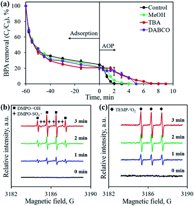
The concentration of leached cobalt ions was determined by ICP-OES. In order to identify the active species for BPA degradation, MeOH, tert-butyl alcohol (TBA), and 1,4-diazabicyclo[2.2.2]octane (DABCO) were employed as scavengers for both SO4˙− and ˙OH, only ˙OH, and 1O2, respectively.18–20 Electron paramagnetic resonance (EPR) experiments were performed to record the signals of radicals using 5,5-dimethyl-1-pyrroline N-oxide (DMPO) and 2,2,6,6-tetramethyl-4-piperidinol (TEMP) as spin trapping agents on a JEOL JES-FA200 spectrometer.
Results and discussion
Conversion of Co2+–nucleic acid complex to cobalt phosphide/carbon composite
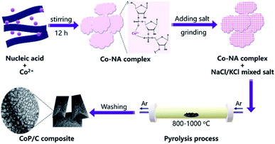
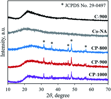
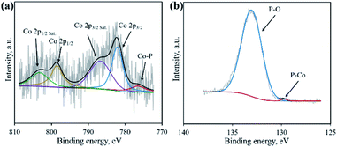
Nucleic acid is one of the essential components in cells, which contains an abundance of carbon, nitrogen and phosphorus. Phosphate groups in the backbone and amino groups in the bases (adenine, guanine, cytosine, etc.) of nucleic acid could possibly coordinate with cobalt ions to form a Co–NA complex precipitate. The abundant C and N in nucleic acid allow for the formation of an advanced carbonaceous material. Therefore, the conversion of a Co–NA complex to a cobalt phosphide/carbon composite is highly possible if the proper treatment method is chosen. Herein, we adopted a facile pyrolysis procedure to achieve the conversion. As illustrated in Fig. 1, first, Co2+ ions coordinated with the functional groups (e.g., phosphate group) of nucleic acid in aqueous solution and precipitated out. The produced precipitate of the Co–NA complex was ground with a mixed salt of NaCl and KCl. Secondly, the powder mixture underwent thermal treatment under an inert gas atmosphere. With increasing pyrolysis temperature, the mixed salt transformed to the molten state. Meanwhile, various gaseous products were generated from the biomass precursor (nucleic acid). Both events are important for the formation of cobalt phosphide/carbon composites, which will be discussed later. After washing off the salt crystal, the final products were obtained.XRD was first adopted to characterize the crystal structure of the as-obtained samples. As shown in Fig. 2, no diffraction peaks are found for the Co–NA complex, indicating that it has an amorphous nature. After pyrolyzing at 800–1000 °C, typical diffraction peaks located at 2θ of 31.5°, 36.2°, 46.1°, 48.0° and 56.7° appear, which agree well with the pattern of CoP (JCPDS card no. 29-0497).10 Recent studies confirmed the possibility of utilizing phosphorus from biomass (yeast) to produce metal phosphides.9,15,16 Different from the reported Co2P crystal phase, CoP is the only crystal phase found in this study. Although the formation mechanism of two kinds of cobalt phosphides is not fully understood, it is believed that the higher content of P in nucleic acid (6.12%) than that of yeast biomass (∼1%) should be one reason. In terms of the C-900 sample without Co2+ incorporation, only broad diffraction peaks (2θ = 21.9° and 43.5°) are observed, indicating that partially graphitized carbon is present.17 To further confirm the formation of CoP, XPS was conducted. As illustrated in Fig. 3a, the XPS Co 2p spectrum is deconvoluted into five peaks, corresponding to the cobalt ion in CoP (776.5 eV), Co 2p3/2 (782.1 eV), Co 2p1/2 (798.5 eV) and satellite peaks (786.7 and 803.2 eV), respectively.21 The XPS P 2p spectrum is deconvoluted into two peaks located at 129.8 eV and 133.1 eV, which agree well with a P–Co bond in CoP and P–O bond in the surface oxidized phosphate (Fig. 3b).21
The elemental compositions of as-obtained samples are listed in Table 1. Interestingly, it is noted that more than 2% of N is preserved in the pyrolyzed samples. It is accepted that the presence of N (N-containing functional groups) in biochar/biocarbon is beneficial for various applications, such as adsorption, energy storage, advanced oxidation processes, etc.22–24 However, a high temperature treatment would induce the remarkable loss of non-metal elements (N, S, etc.). In this study, the utilization of a mixed salt (NaCl and KCl) as the protecting reagent hindered the decomposition of N, leaving a relatively high N content in the pyrolyzed samples.17 The existing state of N is analyzed by XPS as shown in Fig. S1.† Pyridinic-N, pyrrolic-N, graphitic-N and nitric oxide are found after deconvoluting the N 1s spectrum. N doping into the carbon framework is suggested. Based on the elemental composition analysis, the molar ratio of Co![[thin space (1/6-em)]](https://www.rsc.org/images/entities/char_2009.gif) :
:![[thin space (1/6-em)]](https://www.rsc.org/images/entities/char_2009.gif) P in as-obtained samples could be calculated. The developed CP-800, CP-900 and CP-1000 samples all possess a Co
P in as-obtained samples could be calculated. The developed CP-800, CP-900 and CP-1000 samples all possess a Co![[thin space (1/6-em)]](https://www.rsc.org/images/entities/char_2009.gif) :
:![[thin space (1/6-em)]](https://www.rsc.org/images/entities/char_2009.gif) P molar ratio close to 1, further confirming the formation of the CoP crystal phase.
P molar ratio close to 1, further confirming the formation of the CoP crystal phase.
| Sample | Elemental composition, wt% | Co![[thin space (1/6-em)]](https://www.rsc.org/images/entities/char_2009.gif) : :![[thin space (1/6-em)]](https://www.rsc.org/images/entities/char_2009.gif) P (molar ratio) P (molar ratio) |
SSAd, m2 g−1 | Vtotal, cm3 g−1 | Vmicroe, cm3 g−1 | Vmicro/Vtotal | |||
|---|---|---|---|---|---|---|---|---|---|
| Ca | Na | Cob | Pc | ||||||
| a Obtained from CHN elemental analysis.b Measured by ICP-OES.c Measured by spectrophotometric method.d Specific surface area obtained from N2 physisorption.e Pore volume obtained from N2 physisorption. | |||||||||
| Nucleic acid | 37.23 | 5.14 | — | 6.12 | — | — | — | — | — |
| Co-NA | 42.44 | 1.07 | 2.72 | 0.74 | 1.93 | — | — | — | — |
| CP-800 | 50.59 | 4.85 | 7.93 | 4.72 | 0.88 | 853.0 | 0.446 | 0.216 | 48.4% |
| CP-900 | 58.95 | 2.60 | 9.89 | 4.87 | 1.07 | 1063.1 | 0.667 | 0.209 | 31.3% |
| CP-1000 | 61.63 | 2.04 | 11.19 | 5.55 | 1.06 | 1124.5 | 0.664 | 0.180 | 27.1% |
| C-900 | 64.14 | 3.33 | — | 1.29 | — | 908.0 | 0.536 | 0.237 | 44.2% |
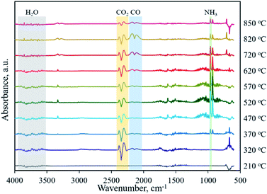
Typically, the formation of metal phosphides requires an organic phosphorus precursor (trioctylphosphine, triphenylphosphine, or trioctylphosphine oxide) or inorganic precursor (NaH2PO2, red phosphorus, etc).4 In situ emitted or extraneously introduced reducing gases (H2, CO, CH4, PH3, etc.) were believed to be crucial for the conversion of high valence Px+ in the precursor to low valence Py− in the phosphide. In this work, we demonstrate the successful fabrication of CoP without introducing a hazardous P precursor. The inherent and environmentally benign phosphate in nucleic acid functioned as the P precursor, underwent a reduction process, and was finally converted to phosphide. To determine the reduction mechanism of P in such a conversion process, TG-MS and TG-IR were conducted for the Co–NA complex. Fig. 4a shows the weight loss and corresponding differential thermogravimetric (DTG) curve. The 10.7% weight loss below 200 °C could be ascribed to the adsorbed water molecules in the sample. From 200–400 °C, a 26.5% weight loss is found, which agrees well with the emitted gases of H2O and CO2, as revealed in Fig. 4d. A gradual weight loss occurs in the temperature range of 400–800 °C, which should be the result of the gradual decomposition of organic components in the nucleic acid. Along with the increasing pyrolysis temperature, typical reducing gases including CO, H2 and PH3 are detected (Fig. 4b and c). Particularly, the emitted CO is obvious at an elevated temperature of ∼800 °C, indicating that the applied synthesis temperature (800–1000 °C) for cobalt phosphide in this study is reasonable. FTIR spectra of the gaseous products obtained in the pyrolysis process of the Co–NA complex, as shown in Fig. 5, further confirm the generation of reducing gas CO (2250–2060 cm−1).25 Other gaseous products including H2O (4000–3500 cm−1), CO2 (2400–2250 cm−1) and NH3 (964 cm−1) are also found,25 agreeing well with the TG-MS results. The presence of such reducing gases makes the conversion of phosphate to phosphide highly possible.
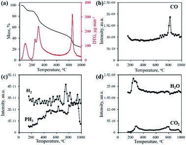 | ||
| Fig. 4 TG and DTG curves (a) and gaseous product emission (b–d) during the pyrolysis process of the Co–NA complex obtained by TG-MS. | ||
The morphologies of the yeast-extracted nucleic acid, Co–NA complex and as-obtained CoP/C samples are observed by FESEM and TEM as shown in Fig. S2† and 6. No distinct morphology is found for the organic precursor of the nucleic acid (Fig. S2a†). The Co–NA complex presents micro-sized particles with aggregation (Fig. 6a). During pyrolysis at 800–1000 °C in the presence of a mixed salt (NaCl and KCl), the organic precursor underwent a dramatic change with the rearrangement of non-metal elements. Irregular particles in the micrometer size range are observed for the C-900, CP-800, CP-900 and CP-1000 samples (Fig. 6b and S2b–d†) without a remarkable difference between them. Interestingly, voids of a few hundred nanometers are present in the pyrolyzed samples. NaCl and KCl in the molten state would become crystals in the cooling process, which could create voids after being washed off.17 Under high magnification, CoP particles are found, as indicated in Fig. 6c by the white arrow. The TEM image of the CP-900 sample in Fig. 6d clearly shows the as-formed voids and CoP nanoparticles (10–20 nm).
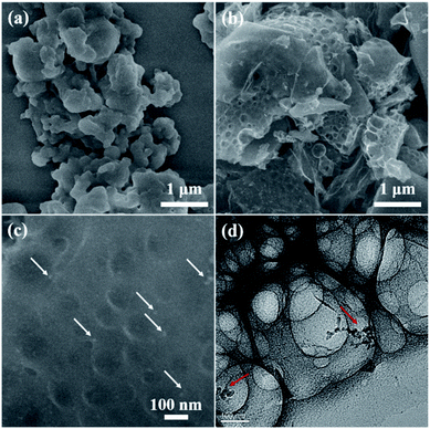 | ||
| Fig. 6 FESEM and TEM images of Co–NA (a) and CP-900 (b–d) samples. Arrows in (c and d) indicate the presence of CoP nanoparticles. | ||
The textural properties of the as-obtained samples were investigated by N2 physisorption. As shown in Fig. 7a, all samples present type IV adsorption isotherms with representative H4-type hysteresis loops, indicating the presence of a mesoporous structure.26 Pore size distribution curves shown in Fig. 7b suggest the existence of both mesopores (average pore size ∼2 nm) and macropores (>50 nm). With increasing pyrolysis temperature, the specific surface area increases from 853.0 m2 g−1 for CP-800 to 1124.5 m2 g−1 for CP-1000, along with an increase of the total pore volume. The addition of the mixed salt (NaCl and KCl) in the precursor is believed to be important component in creating pores. At elevated temperatures, the mixed salt in the molten state could etch the carbon structure.17,27 Meanwhile the molten salt would become crystalline salt and embed into the carbon structure upon cooling down. After removing the salt by washing, the pore structure is formed. Interestingly, it is calculated that the micropore percentage (Vmicro/Vtotal) decreases from 48.4% of CP-800 to 27.1% of CP-1000 with increasing pyrolysis temperature from 800 to 1000 °C (Table 1). As shown in Fig. 4, gases are continually produced during pyrolysis process, even after 800 °C. The as-produced gases may favor the expansion of micropores, leading to the high content of meso- and macro-pores for the CP-1000 sample.
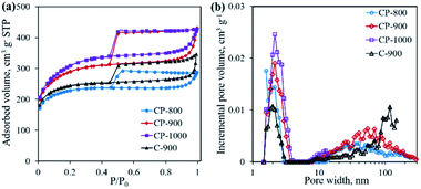 | ||
| Fig. 7 N2 adsorption–desorption isotherms (a) and pore size distribution curves (b) of C-900 and cobalt phosphide/carbon composite samples. | ||
Through the above material characterization, the developed CoP/C is suggested to be a CoP/N-doped porous carbon composite. In the synthesis process (Fig. 1), the molten salt not only hindered the loss of N, which favored the conservation of N-containing functional groups, but also assisted the formation of a porous carbon structure. The reducing gases played a crucial role in the reduction of phosphate to phosphide, which finally led to the formation of CoP.
BPA removal through adsorption and advanced oxidation process
The developed CoP/C composites possess high specific surface area and porosity, which implies their potential application in pollutant adsorption. The presence of CoP can also serve as a PMS activator for the catalytic degradation of organic pollutants.10 In this study, we chose the typical organic molecule BPA, an endocrine disrupter commonly applied in the plastic industry, as a model pollutant to evaluate the performance of CoP/C for pollutant removal. As shown in Fig. 8, all samples exhibit a considerable adsorption ability for BPA. Except for CP-800 with the lowest specific surface area, the other samples could remove 70.9–75.5% BPA in 60 min by adsorption. Typically, the high percentage of micropores in a sample would lead to strong diffusion resistance, which slows down pollutant adsorption rate. Therefore, the BPA adsorption rate follows the order of CP-1000 > CP-900 > C-900 > CP-800, which is consistent with the meso- and macro-pore percentage order for samples (Table 1). Once the adsorption equilibrium is achieved, the oxidant PMS was added into the reaction system (time of 0 min in Fig. 8) to initiate the further catalytic degradation of BPA by the AOP. In the absence of a solid sample, PMS alone barely degraded BPA due to the limited efficiency of the active species generation. Only ∼1% of BPA was degraded in 45 min. Remarkably, in the presence of the as-developed samples, BPA could be totally removed with different degradation rates. CP-800 could achieve 100% BPA degradation in 45 min with a pseudo-first-order reaction rate constant (k) of 0.151 min−1 (Fig. S3†). Increasing the pyrolysis temperature to 900 °C and 1000 °C not only promoted the pore structure improvement of CP-900 and CP-1000, but also facilitated BPA degradation. 100% BPA degradation efficiency is reached in 2 min and 10 min for CP-900 and CP-1000, corresponding to pseudo-first-order reaction rate constants of 1.730 min−1 and 0.406 min−1 (Fig. S3†), respectively. Interestingly, it was found that the sample without CoP involvement (C-900) also performed well for BPA degradation. 100% BPA degradation efficiency was obtained in 30 min with a pseudo-first-order reaction rate constant of 0.181 min−1. Generally, PMS can be activated by metal ions (homogeneous or heterogeneous) to generate a highly active sulfate radical and hydroxyl radical. Free Co2+ ions and Co2+-containing heterogeneous catalysts (Co3O4, Co2P, CoP, CoFe2O4, etc.) are typical examples.9,10,28–31 Therefore, the presence of CoP is of great importance for PMS activation in this study. Besides, PMS activation based on metal-free catalysts (graphene, g-C3N4, N-doped carbon, nano-diamond, etc.) has been reported recently, which also shows an efficient degradation ability for organic pollutants due to the generation of reactive species (1O2) through a non-radical pathway.32–35 The partial graphitization and N-doping properties of the carbon component in the developed sample enabled the efficient activation of PMS for BPA degradation. Overall, the advanced features of the CoP/C sample, including a well-constructed pore structure, crystallized CoP and partially graphitized carbon with N-doping, could achieve the efficient removal of BPA through both the adsorption and advanced oxidation process.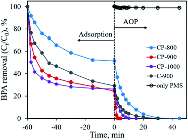 | ||
| Fig. 8 BPA removal through adsorption and advanced oxidation processes. Experimental conditions: [BPA]0 = 0.1 mmol L−1, [catalyst] = 0.4 g L−1, [PMS] = 0.4 g L−1. | ||
Metal ion leaching was commonly found in the process of PMS activation when heterogeneous metal-containing catalysts were adopted because the H+ ion released from the PMS molecule would decrease the solution pH from near neutral to ∼3. Considering the possible toxicity of the metal ion, it is necessary to monitor the leached metal ion concentration. When CoP/C samples were adopted for PMS activation, the leached Co2+ concentration was in the range of 0.54–0.65 mg L−1, corresponding to the loss of 1.45–1.70% of cobalt from the samples. Both values were comparable or even lower than that of reported studies.9,29,36 Moreover, the leached Co2+ concentration is within the regulatory limit (1.0 mg L−1, environmental quality standards for surface water, GB 3838-2002, China). The small leaching percentage could possibly be ascribed to the small particle size and good crystallization of CoP.
The initial solution pH is an important factor that may affect the removal efficiency of the pollutant and limit the application of the material. Fig. 9 shows the influence of the initial solution pH on BPA removal using CP-900 as both the adsorbent and catalyst. Under the investigated solution pH of 3.0–9.0, no obvious difference in the BPA removal is found. Over 75.5% of BPA is adsorbed in 60 min and the residual BPA could be degraded in 2–3 min once PMS was added into the solution. Even after adjusting the initial solution pH to 11.0, CP-900 could still adsorb 65.9% of BPA in 60 min, although the adsorption kinetics were relatively slow. The residual 35.1% of BPA could also be removed in less than 4 min through the catalytic reaction. Therefore, the developed CP-900 sample possesses great potential for organic pollutant removal in a relatively broad solution pH range.
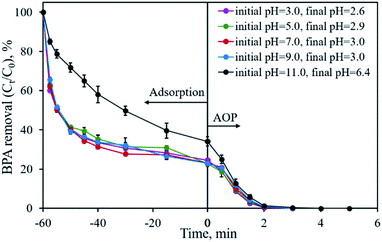 | ||
| Fig. 9 Effect of initial solution pH on BPA removal. Experimental conditions: [BPA]0 = 0.1 mmol L−1, [CP-900] = 0.4 g L−1, [PMS] = 0.4 g L−1. | ||
Mechanism of PMS activation for BPA degradation
Previous studies confirmed that the main active species from PMS activation included a sulfate radical (SO4˙−), hydroxyl radical (˙OH) and singlet oxygen (1O2), all possessing great oxidation ability for organic pollutants.28,32,37 To identify the active species generated in the developed CoP/C-PMS system, scavenging tests and EPR measurements were conducted and the results are illustrated in Fig. 10. When MeOH, TBA and DABCO were employed as both SO4˙− and ˙OH, only ˙OH, and 1O2 scavenger, respectively, the BPA degradation rates were obviously inhibited (Fig. 10a). A longer reaction time of up to 9 min was required to achieve 100% BPA degradation. Furthermore, typical signals were observed in the EPR spectra when DMPO and TEMP were employed as trapping reagents for the SO4˙− radical, ˙OH radical, and 1O2, respectively (Fig. 10b and c). Both facts confirm the involvement of three kinds of active species in the CoP/C-PMS system which are responsible for the catalytic degradation of BPA.As one of the most active metal ions for PMS activation, Co2+ on the surface of CoP could induce the generation of SO4˙− by transferring one electron to HSO5−, as described in eqn (1). The simultaneously produced Co3+ reacts with HSO5−, resulting in the formation of SO5˙− and the release of H+ (eqn (2)). The released H+ would cause the pH of the solution to drop, as shown in Fig. 9. At the same time, ˙OH could be produced by the reaction between SO4˙− and H2O (eqn (3)). Then, a series of reactions occur between the radicals and PMS, which lead to the generation of 1O2 (eqn (4)–(6)). The presence of N-doped carbon in the CoP/C composite also contributes to the generation of active species. Similar to previous reported studies employing advanced carbon materials for AOPs, the sp2 hybridized carbon structure and graphitic N present in CP-900 could allow the free-flowing of electrons and unpaired electrons, which facilitates the electron transfer to PMS, thereby resulting in the generation of SO4˙− and ˙OH (eqn (7) and (8)).38,39 The as-formed SO4˙− and ˙OH radicals could also participate in the serial reactions as described in eqn (4)–(6), promoting the generation of 1O2. N doping into the carbon structure also disrupts the pristine carbon configuration, which is favorable for the self-decomposition of PMS and subsequent generation of 1O2 through a non-radical process (eqn (9)).40 Finally, SO4˙−, ˙OH and 1O2 attack and degrade BPA, resulting in the formation of various intermediates and finally the mineralization to CO2 and H2O (eqn (10)). Therefore, both CoP and N-doped carbon play crucial roles for PMS activation, which improve the BPA removal efficiency by the AOP.
| Co2+ + HSO5− → Co3+ + SO4˙− + OH− | (1) |
| Co3+ + HSO5− → Co2+ + SO5˙− + H+ | (2) |
| SO4˙− + H2O → SO42− + ˙OH + H+ | (3) |
| SO4˙− + HSO5− → SO5˙− + HSO4− | (4) |
| ˙OH + HSO5− → SO5˙− + H2O | (5) |
| 2SO5˙− + H2O → 2HSO4− + 1.51O2 | (6) |
| HSO5− + e− → SO4˙− + OH− | (7) |
| HSO5− + e− → SO42− + ˙OH | (8) |
| HSO5− + SO52− → HSO4−˙ + SO42− + 1O2 | (9) |
| SO4˙−/˙OH/1O2 + BPA → intermediates → CO2 + H2O | (10) |
Recycle study and BPA analogues removal
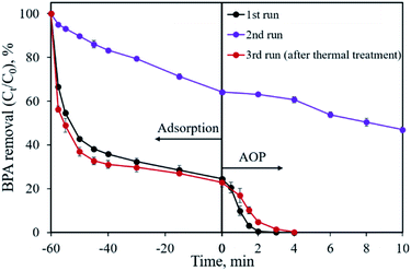
The reusability of the CoP/C sample was evaluated by a recycling study, as shown in Fig. 11. In the first run, 75.5% of BPA was removed by adsorption and the residual 24.5% of BPA was degraded in 3 min by the AOP. However, a dramatic removal efficiency decrease was found in the second run, both in the adsorption and AOP. Only 35.8% of BPA was removed in 60 min by adsorption, while the following AOP degraded 17.3% of BPA in 10 min. Based on previous studies, one possible reason for the removal efficiency decrease is that the reaction intermediates are covering the surface of the sample.18 We attempted a thermal treatment method to reactivate the CP-900 sample. Fortunately, the BPA removal capability of CP-900 was almost totally recovered after re-calcination at 400 °C for 2 h under Ar flow. Compared with the first run, a similar adsorption behavior and slightly slow catalytic reaction kinetics were observed for the regenerated sample in the third run. Therefore, the CP-900 sample could be reused after proper regeneration treatment.BPA analogues such as bisphenol AF (BPAF), bisphenol F (BPF) and bisphenol S (BPS) were also considered as removal pollutant targets using the developed CP-900 sample as both the adsorbent and catalyst. As illustrated in Fig. S4,† CP-900 shows a considerable adsorption capability for BPA analogues with 62.5%, 82.8% and 84.2% removal efficiencies in 60 min for BPAF, BPF and BPS, respectively. The following catalytic process further degrades 34.8% of BPAF and 13.8% of BPS in 10 min, respectively. The overall removal efficiency for BPAF and BPS is 97.3% and 96.6%, respectively. In terms of BPF, the catalytic process could totally remove the residual pollutant in 4 min. The slightly low adsorption removal efficiency for BPAF might be ascribed to its –CF3 group that has a relatively large size. Typical treatments by anaerobic sludge, photo-degradation and biodegradation are not effective for BPS, implying the difficulty of its catalytic removal.41 Overall, the developed CoP/C sample is recyclable and applicable for the removal of BPA analogues.
Conclusions
By coordinating metal ions with a phosphorus-containing biomass of nucleic acid, a single source precursor Co–NA complex was formed, thus enabling the formation of a CoP/carbon composite by pyrolysis. Assisted with TG-MS and TG-IR analysis, we verified that in situ generated reducing gases in the pyrolysis process were responsible for the conversion of phosphate in the precursor to phosphide in CoP. Meanwhile, the adoption of a mixed salt as the protecting agent for N conservation and etching agent for pore construction favored the formation of N-doped porous carbon. Benefiting from the advanced features of a hierarchical pore structure, well-crystallized CoP and N-doped nature, the developed bifunctional CoP/carbon composite performed well for the removal of model pollutant BPA by adsorption and the advanced oxidation process. Through this study, we demonstrate the feasibility of utilizing an environmentally benign precursor for the construction of advanced materials for organic pollutant remediation.Conflicts of interest
There are no conflicts to declare.Acknowledgements
The authors gratefully acknowledge funding support from the National Natural Science Foundation of China (grant number 21808147). We thank Prof. Hui Li from School of Chemical Engineering for the kind assistance on material characterizations.References
- S. T. Oyama, T. Gott, H. Y. Zhao and Y. K. Lee, Catal. Today, 2009, 143, 94–107 CrossRef CAS.
- M. C. Alvarez-Galvan, J. M. Campos-Martin and J. L. G. Fierro, Catalysts, 2019, 9, 293 CrossRef.
- Y. M. Shi and B. Zhang, Chem. Soc. Rev., 2016, 45, 1781 RSC.
- Y. Wang, B. Kong, D. Y. Zhao, H. T. Wang and C. Selomulya, Nano Today, 2017, 15, 26–55 CrossRef CAS.
- W. P. Li, G. Cheng, M. Sun, Z. X. Wu, G. L. Liu, D. S. Su, B. Lan, S. X. Mai, L. Y. Chen and L. Yu, Nanoscale, 2019, 11, 17084–17092 RSC.
- S. Cao, C. J. Wang, W. F. Fu and Y. Chen, ChemSusChem, 2017, 10, 4306–4323 CrossRef CAS.
- X. Wang, H. M. Kim, Y. Xiao and Y. K. Sun, J. Mater. Chem. A, 2016, 4, 14915–14931 RSC.
- C. Alexopoulou, A. Petala, Z. Frontistis, C. Drivas, S. Kennou, D. I. Kondarides and D. Mantzavinos, Appl. Catal., B, 2019, 244, 178–187 CrossRef CAS.
- W. H. Tong, Y. Xie, H. Q. Luo, J. Y. Niu, W. Y. Ran, W. R. Hu, L. Y. Wang, C. H. Yao, W. B. Liu, Y. K. Zhang and Y. B. Wang, Chem. Eng. J., 2019, 378, 122187 CrossRef CAS.
- R. Luo, C. Liu, J. S. Li, J. Wang, X. R. Hu, X. Y. Sun, J. Y. Shen, W. Q. Han and L. J. Wang, J. Hazard. Mater., 2017, 329, 92–101 CrossRef CAS PubMed.
- R. Prins and M. E. Bussell, Catal. Lett., 2012, 142, 1413–1436 CrossRef CAS.
- X. Gong, S. S. Liu, C. Y. Ouyang, P. Strasser and R. Z. Yang, ACS Catal., 2015, 5, 920–927 CrossRef CAS.
- L. Zhao, RSC Adv., 2017, 7, 13904–13910 RSC.
- W. Wan, Q. Wang, L. Zhang, H. W. Liang, P. Chen and S. H. Yu, J. Mater. Chem. A, 2016, 4, 8602–8609 RSC.
- T. Q. Zhang, J. Liu, L. B. Huang, X. D. Zhang, Y. G. Sun, X. C. Liu, D. S. Bin, X. Chen, A. M. Cao, J. S. Hu and L. J. Wan, J. Am. Chem. Soc., 2017, 139, 11248–11253 CrossRef CAS PubMed.
- G. X. Li, J. Y. Yu, J. Jia, L. J. Yang, L. L. Zhao, W. J. Zhou and H. Liu, Adv. Funct. Mater., 2018, 28, 1801332 CrossRef.
- P. Li, H. Xie, Y. Liu, J. Wang, Y. Xie, W. Hu, T. Xie, Y. Wang and Y. Zhang, J. Power Sources, 2019, 439, 227096 CrossRef CAS.
- Y. Xie, P. Y. Li, Y. Zeng, X. Li, Y. X. Xiao, Y. B. Wang and Y. K. Zhang, Chem. Eng. J., 2018, 335, 728–736 CrossRef CAS.
- J. Z. Meng, F. Xu, S. J. Yuan, Y. Mu, W. Wang and Z. H. Hu, Chem. Eng. J., 2019, 355, 130–136 CrossRef CAS.
- C. Huang, Y. L. Wang, M. Gong, W. Wang, Y. Mu and Z. H. Hu, Sep. Purif. Technol., 2020, 230, 115877 CrossRef CAS.
- J. Bai, B. J. Xi, H. Z. Mao, Y. Lin, X. J. Ma, J. K. Feng and S. L. Xiong, Adv. Mater., 2018, 30, 1802310 CrossRef PubMed.
- X. Y. Xu, Y. L. Zheng, B. Gao and X. D. Cao, Chem. Eng. J., 2019, 368, 564–572 CrossRef CAS.
- Y. Q. Guo, W. Liu, R. T. Wu, L. J. Sun, Y. Zhang, Y. P. Cui, S. Liu, H. L. Wang and B. H. Shan, ACS Appl. Mater. Interfaces, 2018, 10, 38376–38386 CrossRef CAS PubMed.
- H. Z. Wang, W. Q. Guo, B. H. Liu, Q. L. Wu, H. C. Luo, Q. Zhao, Q. S. Si, F. Sseguya and N. Q. Ren, Water Res., 2019, 160, 405–414 CrossRef CAS PubMed.
- H. P. Chen, Y. P. Xie, W. Chen, M. W. Xia, K. X. Li, Z. Q. Chen, Y. Q. Chen and H. P. Yang, Energy Convers. Manage., 2019, 196, 320–329 CrossRef CAS.
- M. Thommes, K. Kaneko, A. V. Neimark, J. P. Olivier, F. Rodriguez-Reinoso, J. Rouquerol and K. S. W. Sing, Pure Appl. Chem., 2015, 87, 1051–1069 CAS.
- N. Fechler, T. P. Fellinger and M. Antonietti, Adv. Mater., 2013, 25, 75–79 CrossRef CAS PubMed.
- G. P. Anipsitakis and D. D. Dionysiou, Environ. Sci. Technol., 2004, 38, 3705–3712 CrossRef CAS PubMed.
- W. Zhang, H. L. Tay, S. S. Lim, Y. S. Wang, Z. Y. Zhong and R. Xu, Appl. Catal., B, 2010, 95, 93–99 CrossRef CAS.
- J. Li, M. J. Xu, G. Yao and B. Lai, Chem. Eng. J., 2018, 348, 1012–1024 CrossRef CAS.
- R. Luo, C. Liu, J. S. Li, C. H. Wang, X. Y. Sun, J. Y. Shen, W. Q. Han and L. J. Wang, J. Mater. Chem. A, 2018, 6, 3454–3461 RSC.
- X. G. Duan, H. Q. Sun and S. B. Wang, Acc. Chem. Res., 2018, 51, 678–687 CrossRef CAS PubMed.
- B. C. Huang, J. Jiang, G. X. Huang and H. Q. Yu, J. Mater. Chem. A, 2018, 6, 8978–8985 RSC.
- X. G. Duan, Z. M. Ao, H. Q. Sun, S. Indrawirawan, Y. X. Wang, J. Kang, F. L. Liang, Z. H. Zhu and S. B. Wang, ACS Appl. Mater. Interfaces, 2015, 7, 4169–4178 CrossRef CAS PubMed.
- K. Y. A. Lin and Z. Y. Zhang, Chem. Eng. J., 2017, 313, 1320–1327 CrossRef CAS.
- Y. B. Wang, Y. Xie, S. M. Yin, R. Xu and R. Lau, J. Taiwan Inst. Chem. Eng., 2016, 68, 246–253 CrossRef CAS.
- B. T. Zhang, Y. Zhang, Y. H. Teng and M. H. Fan, Crit. Rev. Environ. Sci. Technol., 2015, 45, 1756–1800 CrossRef CAS.
- W. R. Hu, Y. Xie, S. Lu, P. Y. Li, T. H. Xie, Y. K. Zhang and Y. B. Wang, Sci. Total Environ., 2019, 680, 51–60 CrossRef CAS PubMed.
- X. G. Duan, H. Q. Sun, Y. X. Wang, J. Kang and S. B. Wang, ACS Catal., 2015, 5, 553–559 CrossRef CAS.
- P. Liang, C. Zhang, X. Duan, H. Sun, S. Liu, M. O. Tade and S. Wang, Environ. Sci.: Nano, 2017, 4, 315–324 RSC.
- T. Yang, L. Wang, Y. L. Liu, Z. S. Huang, H. Y. He, X. S. Wang, J. Jiang, D. W. Gao and J. Ma, Water Res., 2019, 148, 115–125 CrossRef CAS PubMed.
Footnote |
| † Electronic supplementary information (ESI) available: XPS spectra, FESEM images, reaction kinetic, BPA analogues removal. See DOI: 10.1039/d0ra00998a |
| This journal is © The Royal Society of Chemistry 2020 |

