 Open Access Article
Vortex fluidic mediated synthesis of polysulfone†‡
Aghil Igder ab,
Scott Pye
 b,
Ahmed Hussein Mohammed Al-Antaki
 b,
Alireza Keshavarz
 a,
Colin L. Raston
 *b and
Ata Nosratia
aSchool of Engineering, Edith Cowan University, Joondalup, Perth, WA 6027, Australia
bFlinders Institute for Nanoscale Science and Technology, College of Science and Engineering, Flinders University, Adelaide, SA 5042, Australia. E-mail: colin.raston@flinders.edu.au
First published on 14th April 2020
Abstract
Polysulfone (PSF) was prepared under high shear in a vortex fluidic device (VFD) operating in confined mode, and its properties compared with that prepared using batch processing. This involved reacting the pre-prepared disodium salt of bisphenol A (BPA) with a 4,4′-dihalodiphenylsulfone under anhydrous conditions. Scanning electron microscopy (SEM) established that in the thin film microfluidic platform, the PSF particles are sheet-like, for short reaction times, and fibrous for long reaction times, in contrast to spherical like particles for the polymer prepared using the conventional batch synthesis. The operating parameters of the VFD (rotational speed of the glass tube, its tilt angle and temperature) were systematically varied for establishing their effect on the molecular weight (Mw), glass transition temperature (Tg) and decomposition temperature, featuring gel permeation chromatography (GPC), differential scanning calorimetry (DSC) and thermal gravimetric analysis (TGA) respectively. The optimal VFD prepared PSF was obtained at 6000 rpm rotational speed, 45° tilt angle and 160 °C, for 1 h of processing with Mw ∼10![[thin space (1/6-em)]](https://www.rsc.org/images/entities/char_2009.gif) 000 g mol−1, Tg ∼158 °C and decomposition temperature ∼530 °C, which is comparable to the conventionally prepared PSF.
000 g mol−1, Tg ∼158 °C and decomposition temperature ∼530 °C, which is comparable to the conventionally prepared PSF.
Introduction
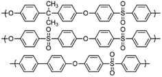
Polymerisation reactions can be classified as arising from step-growth and chain-growth mechanisms, corresponding to condensation and addition reactions respectively.1,2 Condensation polymers involve the reaction between two monomers in building the macromolecule, with or without the elimination of a small molecule such as water.3,4 Among different types of condensation reactions, nucleophilic substitution features the most for preparing commercial organic polymers, such as in epoxide polymerisation,3 or in the production of polysulfide rubbers from aliphatic dichlorides and sodium sulphide.3,5Polysulfone (PSF) is a common thermoplastic polymer and a popular polymer incorporated in nano-filtration (NF) membranes. Aliphatic PSFs have unattractive physical properties including melting point and glass transition temperature, in contrast to PSFs incorporating aromatic moieties, which are prepared commercially via nucleophilic substitution reactions, Scheme 1a,1,5 with the structure of a PSF repeating unit shown in the ESI.‡ Aromatic based PSFs feature in different applications, having desirable thermal,6 chemical and mechanical stabilities.7,8 These polymers are also known as polyethersulfone (PESs) or polyphenylsulfone (PPSFs), depending on the nature of the backbone, Table 1.1,9 The main difference between different types of PSF comes from the bisphenol (BP) repeating unit which controls certain properties, including glass transition temperature (Tg), Table 2.1 Aromatic PSF is commercially obtained by condensation of equimolar quantities of 4,4′-dihalodiphenylsulfone (DHDPS) and a BP in the presence of a base.1,5 This involves two separate steps, Scheme 1b; firstly, BPA is converted to the disodium salt (DiNa salt) by the addition of base, followed by a substitution reaction with dichlorodiphenyl-sulfone (DCDPS). Removal of water by-product generated in the first step is required to prevent hydrolysis of the DCDPS and facilitates the formation of higher molecular weight polymer.1,5 Dimethyl sulfoxide (DMSO) and sulfolane have been used to overcome the otherwise limited solubility of the DiNa salt of BPA under anhydrous conditions. Co-solvents such as chlorobenzene or toluene have also been used to increase the solubility of the salt.1,5 Reaction temperatures >∼120 °C are effective in removing water from the reaction with >150 °C effective in driving the polymerisation to completion, and below this, low molecular weight sodium-capped oligomers precipitate on the internal surface of the reaction vessels.5 Preparing PSF using conventional batch processing,1,5 has some limitations, including that the processing is time consuming and energy intensive, and downstream processing is required to remove by-products.
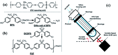 | ||
| Scheme 1 (a) Aromatic PSF repeating unit in PSF, (b) schematic of PSF synthesis involving nucleophilic substitution, and (c) diagram of the vortex fluidic device (VFD).23 | ||
We hypothesised that the high shear stress and intense micro-mixing in thin film microfluidics has potential to overcome these issues, imparting fast kinetics and with simplicity of the processing.10,11
The VFD, is a relatively new thin film microfluidic platform with a diverse range of applications, including graphene exfoliating, enhancing chemical reactivity and selectivity,12,13 as in the synthesis of small molecule pharmaceuticals,14,15 fabricating composite nanomaterials,16 and controlling the pore size of mesoporous silica,17 to mention a few. The rate of water evaporation in the VFD is dramatically increased, due to the large surface area of the thin film created inside the rapidly rotating VFD tube, and there is high heat and mass transfer, with improved reaction homogeneity, and when operating under continuous flow conditions, clogging is not an issue, unlike conventional channel based microfluidics.18 It has also been used in preparing polymeric nanoparticles, notably polyethylenimine (PEI) nanoparticles19 and cross linked bovine serum albumin (BSA) with glutaraldehyde,20 and polymer coated superparamagnetic magnetite nanoparticles,21 as well as manipulating the florescent properties of hyper-branched polymers.22 The benefits of shear stress in the dynamic thin film in the VFD has not been explored for preparing PSF. This is addressed herein, while avoiding the use of potentially toxic reagents such as chlorinated co-solvents. This led to a new synthesis of the PSF, with the optimal conditions established by systematically exploring the operating parameter space of the VFD, including rotational speed, processing time, tilt angle of the tube, and temperature. The processing outcomes were also assessed relative to the glass transition temperature (Tg), molecular weight (Mw), particle size and shape, production yield and thermal stability of the PSF, in comparison with the polymer prepared using conventional batch processing. Different processing parameters in the VFD are likely to produce materials of different morphologies, which is important in the applications of PSF, such as in membrane fabrication.
Experimental
Materials
All chemicals were used as received unless otherwise stated. High purity bisphenol A, [2,2-bis(4-hydroxyphenyl) propane], (BPA) (99%) and 4,4′-dichlorodiphenyl sulfone (DCDPS) (98%) and sodium hydroxide pellets (>97%) were purchased from Sigma Aldrich. Dimethyl sulfoxide (DMSO) (99.9%) and chlorobenzene (99.9%) were purchased from RCI Labscan Limited, with tetrahydrofuran (THF) (99.95%) purchased from Chem-Supply. Ultrapure Milli-Q water was used for preparing aqueous solutions. DMSO was triple distilled before use and kept under nitrogen to limit adsorption of water. The vortex fluidic device (VFD) had a mounted heating block, effective in heating liquids in the tube, up to 175 °C.PSF polymerisation
PSF was initially prepared according to the batch procedure5 detailed in the ESI.‡ For VFD processing, BPA (228 mg, 1.0 mmol) and DMSO (1.0 mL) were placed in the VFD tube (20 mm O.D., 17.5 I.D., 18.5 cm long) and rotated at 4000 rpm at 60 °C for 5 min, affording a clear colourless solution.This reaction was also effective at room temperature, but the processing took 20 minutes. In contrast to the conventional method, no co-solvent was required. An aqueous solution of NaOH (103 μL, 50.2% w/w, 2 mmol) was then added to the tube, which was rotated at 4000 rpm, 45° tilt angle and 60 °C for 15 min. A solution of DCDPS (287 mg, 1 mmol) in DMSO (1.0 mL) was then added to the tube rotating at specific speeds (rpm), tilt angle (°), temperatures (°C), for specified times (min), for every designated experiment in Table S1 & Fig. S1.‡ At the end of each reaction, the sample was purified by filtration and any solid (NaCl by-product) discarded, whereupon, ethanol (10 mL) was added. The resulting coagulated white solid was washed twice and centrifuged (4 min, 805 RFC). The product was then filtered and dried for 2 h at 70 °C, affording PSF as a white solid, with the yield of product determined. In addition, for specific operational conditions, Mw, Tg and temperature variation profiles were determined at the optimal conditions, using gel permeation chromatography (GPC), differential scanning calorimetry (DSC) and thermal gravimetric analysis (TGA) respectively.
Characterization
The intermediate DiNa salt of BPA and the final VFD mediated PSF were characterized using NMR spectroscopy, recorded in DMSO-d6 and CDCl3 respectively (600 MHz Bruker instrument), and FT-IR spectroscopy (PerkinElmer ATR Fourier Transform spectrometer). 1H-NMR spectra were acquired using a relaxation delay-time of 4 seconds. All chemical shifts are presented in ppm, using residual solvent as the internal standard. Scanning electron microscope (SEM) images were recorded on an Inspect FEI F50 SEM. Average molecular weights (Mw) and molecular weight distributions24 were determined using a double detection Shimadzu GPC instrument equipped with an Ultraviolet (UV) and Refractive Index (RI) detectors. Tg and thermal stability measurements used a PerkinElmer DSC 8000 and TGA 8000 instrument, respectively, with instrument settings included in the ESI.‡ These properties were established for all polymers prepared in this study, in establishing the optimal operating parameters of the VFD, namely rotational speed (ω), tilt angle (θ), reaction time (t) and temperature (T). The optimal operational conditions are defined as those for forming the polymer with the highest Tg, Mw, thermal stability, and formed in the highest yield.Results and discussion
The synthesis of PSF was conducted in the VFD and using batch processing for direct comparison on the effect of the unique fluid flow in the microfluidic platform. The production of the intermediate and final products was firstly confirmed using NMR and FTIR spectroscopy. Then the operating parameters of the VFD were systematically explored in mapping out how these affect the nature of the PSF with respect to Tg, Mw and thermal stability (DSC, GPC and TGA). Products were also studied for their morphological properties using SEM images.Synthesis of DiNa salt of BPA
FT-IR and NMR spectroscopy25 confirmed the formation of the DiNa salt of BPA and PSF, for both VFD and batch processing. The choice of solvent is critical for any process.26 The DiNa salt of BPA, as the product of first step, is highly soluble in high boiling point DMSO (189 °C)26 but this is difficult to remove for the isolation of the polymer and isolating the product to be characterized. In contrast, the DiNa salt is only sparingly soluble in THF, and to be able to isolate it for characterization purposes, this was the solvent of choice, with the precipitated salt washed with EtOAc. FTIR spectra of DiNa salt of BPA (Fig. S2a‡) obtained in the first step in the VFD, at ω 4000 rpm, θ 45° and T 60 °C for 5 min, clearly showed the removal of –OH stretching in forming the corresponding conjugate base, with peaks assignable to aromatic C![[double bond, length as m-dash]](https://www.rsc.org/images/entities/char_e001.gif) C (1508–1611 cm−1), C–O (1050–1300 cm−1) and C–H (1365–1465 cm−1).27,28 Peaks at 3000 cm−1 and above 3500 cm−1, are attributed to THF29,30 which can bind to metal centres, including sodium. 1H-NMR of BPA in DMSO-d6 (Fig. 1a) has peaks at ∼1.53 and 9.13 ppm, assigned to the aliphatic protons and hydroxyl groups, respectively, with the later removed on reacting with base in forming DiNa. There are also peaks at 6.97 and 6.64 ppm corresponding to the aromatic protons of BPA (Fig. 1b).31 Overall, changes in the 1H-NMR spectra30 are consistent with the formation of the DiNa salt (Fig. 1a) and the removal of water from the reaction mixture in the VFD. Such removal of water has been reported for the continuous flow synthesis of di-carboxylate esters synthesis.18 For batch synthesis of DiNa, FTIR established that the longer the reaction time, the broader the –OH stretching peak, whereas for VFD processing the –OH stretching is smaller,27,28 which is attributed to water dissipation in the VFD (Fig. S2b‡).
C (1508–1611 cm−1), C–O (1050–1300 cm−1) and C–H (1365–1465 cm−1).27,28 Peaks at 3000 cm−1 and above 3500 cm−1, are attributed to THF29,30 which can bind to metal centres, including sodium. 1H-NMR of BPA in DMSO-d6 (Fig. 1a) has peaks at ∼1.53 and 9.13 ppm, assigned to the aliphatic protons and hydroxyl groups, respectively, with the later removed on reacting with base in forming DiNa. There are also peaks at 6.97 and 6.64 ppm corresponding to the aromatic protons of BPA (Fig. 1b).31 Overall, changes in the 1H-NMR spectra30 are consistent with the formation of the DiNa salt (Fig. 1a) and the removal of water from the reaction mixture in the VFD. Such removal of water has been reported for the continuous flow synthesis of di-carboxylate esters synthesis.18 For batch synthesis of DiNa, FTIR established that the longer the reaction time, the broader the –OH stretching peak, whereas for VFD processing the –OH stretching is smaller,27,28 which is attributed to water dissipation in the VFD (Fig. S2b‡).
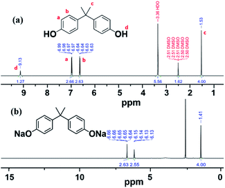 | ||
| Fig. 1 1H-NMR spectra of (a) BPA and (b) DiNa salt of BPA obtained in the VFD in THF. 1H-NMR measurements were recorded in DMSO-d6. | ||
Synthesis of PSF
Fig. S3 and S4–S11‡ show the FTIR and NMR spectra for PSF prepared using both conventional32 and VFD processing, as well as starting material for comparison. Fig. S10 and S11‡ show the 1H and 13C NMR of VFD synthesized PSF at the optimised VFD condition, respectively, matching the corresponding spectra for highly porous PSF membranes.33 The smaller peaks for the aromatic region in Fig. S10,‡ can be assigned to terminal groups of the polymer. In targeting the formation of high molecular weight polymer in the VFD, this region should be minimal.33Varying VFD operational parameters
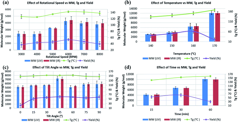
Experiments T1 to T6 in Table S1‡ were carried out to establish the effect of varying ω, from 3000 to 8000 rpm. Average molecular weight (Mw), Tg, and decomposition temperature, as well as yield were determined for all experiments. Mw, measured using GPC, were in the range ∼2000 to ∼11![[thin space (1/6-em)]](https://www.rsc.org/images/entities/char_2009.gif) 000 g mol−1, with the highest, ∼4300 g mol−1, formed at ω 6000 rpm, heating at 150 °C over 30 min, and θ 45° (T4), with little change at higher speeds (Fig. 2a). DSC measurements to determine Tg were carried out under a nitrogen/air atmosphere, with the highest Tg reported thus far for PSF at ∼187 °C.33 Tg values for T1, to T6 were ∼126, 125, 135, 142, 141, and 138 °C respectively, with the highest for PSF formed at 6000 rpm. The highest yield of isolated PSF, 53%, also corresponds to experiment T4, with yields lower for increasing and reducing ω, at 37% and 39% for 3000 and 8000 rpm, respectively. The results clearly show that the properties of PSF (Mw and Tg) change on changing the rotational speed of the tube in the VFD, with 6000 rpm optimal, Fig. 2a.
000 g mol−1, with the highest, ∼4300 g mol−1, formed at ω 6000 rpm, heating at 150 °C over 30 min, and θ 45° (T4), with little change at higher speeds (Fig. 2a). DSC measurements to determine Tg were carried out under a nitrogen/air atmosphere, with the highest Tg reported thus far for PSF at ∼187 °C.33 Tg values for T1, to T6 were ∼126, 125, 135, 142, 141, and 138 °C respectively, with the highest for PSF formed at 6000 rpm. The highest yield of isolated PSF, 53%, also corresponds to experiment T4, with yields lower for increasing and reducing ω, at 37% and 39% for 3000 and 8000 rpm, respectively. The results clearly show that the properties of PSF (Mw and Tg) change on changing the rotational speed of the tube in the VFD, with 6000 rpm optimal, Fig. 2a.
Experiments T7 to T12, Table S1,‡ were at ω 6000 rpm, θ 45°, for 30 min at different temperatures. The effect of the choice of temperature impacts on the molecular weight of the PSF. There is clearly an effect on the temperature of the processing on the Mw of the polymer, and consequently Tg. The highest Mw and Tg were for the PSF prepared at 170 °C, 12![[thin space (1/6-em)]](https://www.rsc.org/images/entities/char_2009.gif) 000 g mol−1 and 168 °C, respectively, Fig. 2b. However, the yield of the isolated product dropped from 61% at 160 °C to 19.4% at 170 °C, and thus 160 °C reaction temperature was regarded as optimal, which is in accordance with temperature in conventional batch polymerisation (155 °C).5 For experiments T7 and T8, at 80 and 120 °C respectively, there was no evidence for the formation of PSF.
000 g mol−1 and 168 °C, respectively, Fig. 2b. However, the yield of the isolated product dropped from 61% at 160 °C to 19.4% at 170 °C, and thus 160 °C reaction temperature was regarded as optimal, which is in accordance with temperature in conventional batch polymerisation (155 °C).5 For experiments T7 and T8, at 80 and 120 °C respectively, there was no evidence for the formation of PSF.
Formation of PSF is incomplete at low temperature (T7 & T8), increasing up to 170 °C, resulting in a higher Mw and Tg. Temperatures higher than ∼160 °C can result in solvent decomposition, discoloration or gelation of the reaction5 and in this context we note that the yield of the product in the VFD drops at 170 °C. The Tg of batch prepared PSF in this research with Mw ∼6300 g mol−1 was ∼106 °C, significantly smaller than the PSF prepared in the VFD with the same Mw, summarised for entry T11, Table S1,‡ Mw ∼6300 g mol−1, Tg ∼152 °C. The relatively high Tg for such a low molecular weight PSF is noteworthy and highlights the novel process in the VFD under high shear.
The tilt angle, θ, in the VFD was varied from 0° (horizontal position) to 90° (vertical position) at intervals of 15°, entries T13–T19, Table S1.‡ There is a significant increase in yield from 21.7% at θ 30° to 59.2% at 45°, Fig. 2c. For θ at 30° and 90° the yields were also relatively high, at 58.3% and 58.1% respectively, but given the higher Mw (∼7100 g mol−1) and Tg (∼153 °C) at θ 45°, this angle was regarded as optimal for the synthesis of PSF in the VFD, and this is in agreement with the outcome of optimisation studies for a number of applications of the device.10–16,23 Understanding the complex fluid flow in general in the VFD is a challenge, and is a major focus of our current research.
The synthesis of PSF in the VFD was then carried out at 160 °C, with ω 6000 rpm and θ 45° for different processing times, entries T20–T22, Table S1.‡ Mw and Tg increased to ∼10![[thin space (1/6-em)]](https://www.rsc.org/images/entities/char_2009.gif) 000 g mol−1 and ∼160 °C, respectively, by increasing the processing time up to 60 min. However, this resulted in a reduction in the yield, down to ∼30% yield, in contrast to 63.7% for 30 min processing time, which has a lower Mw at ∼6700 Mw, Fig. 2d. The lower molecular weight for shorter processing time is consistent with competing reactions, formation of the polymer versus its degradation under prolonged high shear. In this context, we note that polyethylenimine is broken down in the VFD.19 GPC curves for commercial, conventional and VFD synthesized PSF at 6000 rpm, 160 °C, 45 tilt, and 60 min, now regarded as optimal conditions for processing in the VFD, are shown in Fig. 3a. The shorter retention time for commercial PSF is in agreement with its much higher Mw, ∼60
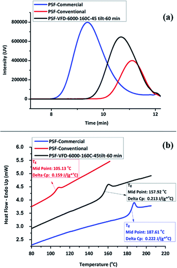
000 g mol−1 and ∼160 °C, respectively, by increasing the processing time up to 60 min. However, this resulted in a reduction in the yield, down to ∼30% yield, in contrast to 63.7% for 30 min processing time, which has a lower Mw at ∼6700 Mw, Fig. 2d. The lower molecular weight for shorter processing time is consistent with competing reactions, formation of the polymer versus its degradation under prolonged high shear. In this context, we note that polyethylenimine is broken down in the VFD.19 GPC curves for commercial, conventional and VFD synthesized PSF at 6000 rpm, 160 °C, 45 tilt, and 60 min, now regarded as optimal conditions for processing in the VFD, are shown in Fig. 3a. The shorter retention time for commercial PSF is in agreement with its much higher Mw, ∼60![[thin space (1/6-em)]](https://www.rsc.org/images/entities/char_2009.gif) 000 g mol−1, with Mw for conventional batch prepared PSF, Mw ∼6000 g mol−1, and that for PSF prepared in the VFD at optimal processing parameters, T22, ∼10
000 g mol−1, with Mw for conventional batch prepared PSF, Mw ∼6000 g mol−1, and that for PSF prepared in the VFD at optimal processing parameters, T22, ∼10![[thin space (1/6-em)]](https://www.rsc.org/images/entities/char_2009.gif) 000 g mol−1. The GPC results show a decrease in retention time of the VFD prepared PSF, the material having a higher Mw compared to the conventional batch prepared PSF. The polydispersity index (PDI) for all these samples were 1.76, 1.78 and 1.76, respectively, and while they are similar, that prepared in the VFD has a narrower Mw distribution, and for the optimal processing parameters in general. In addition, PDIs for specific VFD optimised processing parameters are consistently lower, for example, in the optimal rotational speed, ω 6000 rpm, the PDI is 1.52, T4, Fig. S12 and S13.‡ Lower PDIs for material generated in the VFD are associated with more uniform particle size distributions and highlight the benefit of using the VFD microfluidic platform, ESI (Fig. S14–S25‡). DSC thermograms in Fig. 3b are for commercial and conventional PSF, and optimised VFD fabricated PSF (ω 6000 rpm, 160 °C, θ 45°, and 60 min). All Tg values were collected from the second heating scan to minimise the effect of any evaporation of low volatiles or moisture. The heating curve of the VFD characterized PSF (black curve) has a glass transition at 157.9 °C (mid-point) with a change in the specific heat capacity, cp 0.213 J (g−1 °C). Conventional batch characterized PSF (red curve) has a lower Tg at 105.13 °C with cp 0.159 J (g−1 °C).
000 g mol−1. The GPC results show a decrease in retention time of the VFD prepared PSF, the material having a higher Mw compared to the conventional batch prepared PSF. The polydispersity index (PDI) for all these samples were 1.76, 1.78 and 1.76, respectively, and while they are similar, that prepared in the VFD has a narrower Mw distribution, and for the optimal processing parameters in general. In addition, PDIs for specific VFD optimised processing parameters are consistently lower, for example, in the optimal rotational speed, ω 6000 rpm, the PDI is 1.52, T4, Fig. S12 and S13.‡ Lower PDIs for material generated in the VFD are associated with more uniform particle size distributions and highlight the benefit of using the VFD microfluidic platform, ESI (Fig. S14–S25‡). DSC thermograms in Fig. 3b are for commercial and conventional PSF, and optimised VFD fabricated PSF (ω 6000 rpm, 160 °C, θ 45°, and 60 min). All Tg values were collected from the second heating scan to minimise the effect of any evaporation of low volatiles or moisture. The heating curve of the VFD characterized PSF (black curve) has a glass transition at 157.9 °C (mid-point) with a change in the specific heat capacity, cp 0.213 J (g−1 °C). Conventional batch characterized PSF (red curve) has a lower Tg at 105.13 °C with cp 0.159 J (g−1 °C).
For all samples, the glass transition is superimposed by a small endotherm at 190.1, 108.5, and 160.4 °C, during heating scan, for commercial, conventional and VFD polymers, respectively. The DCS results (Fig. 3b) show a significantly higher Tg for the VFD prepared PSF compared to the conventional batch prepared PSF. This difference presumably relates to the intense micro-mixing and high shear rates in the VFD, and also the high rate of loss of water from the reaction mixture in the device, as established elsewhere.18 However, the Tg for PSF prepared in the VFD is lower than that of commercial PSF (blue curve). Comparative DSC thermograms plots were also recorded in ascertaining the effect of ω on Tg, Fig. S26,‡ showing the best Tg measured is in accordance with the highest Mw polymer obtained at ω 6000 rpm (∼142 °C) while it is ∼125 and 137 °C at ω 4000 and 8000 rpm, respectively.
TGA measurements, carried out based on the setting suggested in Table S2, and Fig. S27,‡ establish a mass loss between 100 and 200 °C (DTG peak) of 7.4 and 0.5% for conventional VFD generated samples respectively, which is attributed to the loss of moisture and lower volatiles. The main decompositions of PSF for VFD processes T9 (140 °C), T10 (150 °C), T11 (160 °C) and T12 (170 °C), conventional processes and commercial material, are at 530.0, 531.9, 533.0, 534.4, 534.6, and 536.4 °C (DTG Peak1), with a mass loss of 68.7, 68.9, 68.9, 66.2, 65.0, and 66.2%, respectively (Fig. S27‡).
The results show that increasing the temperature up to 10 °C during the polymerization reaction has little effect on the main decomposition temperature, and accordingly Mw, Tg, and percent yield were more informative for optimising the processing in the VFD.
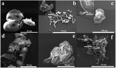
The morphology of PSF is important in its applications, for example, in membranes.34,35 Fig. 4 shows SEM images for drop cast samples of commercial, conventional, and optimised VFD prepared PSF, and coated with ∼5 nm layer of platinum. Commercial PSF has large globular shaped particles, ca. 30 μm in diameter, whereas that formed under batch processing herein are much smaller at submicron dimensions, Fig. 4(a and b), respectively. Interestingly, the size of the particles formed under the optimised VFD processing conditions in the VFD, Fig. 4c, are similar to those of the commercial sample, yet the Mw of the material is significantly less, and the surface morphology is distinctly different. Also, of note is that PSF prepared away from optimised conditions in the VFD, Fig. 4(d–f) have different morphology and apparent particle size. For the shortest reaction time, 15 min, the product is sheet-like, Fig. 4d, changing to semi-spherical particles for 30 min, Fig. 4e, and fibrous material after 90 min, Fig. 4f. More images of the samples are shown in Fig. S28‡ in establishing that the images in Fig. 4 are representative of the bulk materials. The SEM images show that the mechanoenergy delivered into the dynamic thin film in the VFD perturbs the topology of the material, in being able to generate spherical, fibrous or sheet-like products, which is optimal at 6000 rpm, 160 °C, θ 45°, and understanding their formation is major challenge. The origin of this difference possibly relates to the complex fluid dynamics in the VFD becoming increasingly important over time, in moulding the polymer particles. This morphological variation is important in any downstream applications.
Conclusions
The preparation of PSF under high shear in the VFD using the confined mode of operation of the device has been established as an optimised process relative to Mw, Tg and percent yield, an and compared with commercially available material, and that prepared using conventional batch processing. The optimised VFD processing parameters were T 170 °C, ω 6000 rpm, θ 45° and t 30 min, which corresponds has Mw ∼12![[thin space (1/6-em)]](https://www.rsc.org/images/entities/char_2009.gif) 000 g mol−1, Tg 168 °C and decomposition temperature ∼530 °C. However, the lower yield (18%) at this temperature, 160 °C was deemed more optimal, affording Mw ∼7000 g mol−1, Tg ∼154 °C, and ∼64% yield, and for a longer reaction time, 60 min, now affording Mw ∼10
000 g mol−1, Tg 168 °C and decomposition temperature ∼530 °C. However, the lower yield (18%) at this temperature, 160 °C was deemed more optimal, affording Mw ∼7000 g mol−1, Tg ∼154 °C, and ∼64% yield, and for a longer reaction time, 60 min, now affording Mw ∼10![[thin space (1/6-em)]](https://www.rsc.org/images/entities/char_2009.gif) 000 g mol−1 and Tg∼ 158 °C. While the latter results in a lower yield (∼30%), the reaction time can be defined based on the importance of either the Mw or yield of the process.
000 g mol−1 and Tg∼ 158 °C. While the latter results in a lower yield (∼30%), the reaction time can be defined based on the importance of either the Mw or yield of the process.
The VFD prepared PSF has comparable properties relative to that prepared using conventional batch processing, with Mw ∼6000 g mol−1, but this is smaller than that of commercially prepared PSF, ∼60![[thin space (1/6-em)]](https://www.rsc.org/images/entities/char_2009.gif) 000 g mol−1. However, our approach in avoiding the use of toxic reagents such as chlorinated co-solvents (chlorobenzene) is an advance in the field, in endeavouring to develop sustainable technologies. The ability to remove water in situ is also an important part of using the VFD relative to batch processing, in avoiding termination reactions. Also important is the processing time, in changing the morphology of the particles, which may be important in down-stream applications. Indeed, the lower Mw VFD material may open new particle size/chain length specific applications of PSF, further tuned by morphology considerations, sheet like versus globular like particles. We note that the fluid dynamics in the VFD is inherently complex and that this determines the rate of the reactions (high shear and intense micro-mixing) as well as the shape, determined by how the fluid actually flows in the device. This is a major research effort underway involving a number of laboratories. The reduction in percent yield for increasing processing time may arise also from the shear stress resulting in bond cleavage and reduction in the length of the polymer chain. In this context, it is noteworthy that the VFD is effective in breaking down polyethylenamines.19
000 g mol−1. However, our approach in avoiding the use of toxic reagents such as chlorinated co-solvents (chlorobenzene) is an advance in the field, in endeavouring to develop sustainable technologies. The ability to remove water in situ is also an important part of using the VFD relative to batch processing, in avoiding termination reactions. Also important is the processing time, in changing the morphology of the particles, which may be important in down-stream applications. Indeed, the lower Mw VFD material may open new particle size/chain length specific applications of PSF, further tuned by morphology considerations, sheet like versus globular like particles. We note that the fluid dynamics in the VFD is inherently complex and that this determines the rate of the reactions (high shear and intense micro-mixing) as well as the shape, determined by how the fluid actually flows in the device. This is a major research effort underway involving a number of laboratories. The reduction in percent yield for increasing processing time may arise also from the shear stress resulting in bond cleavage and reduction in the length of the polymer chain. In this context, it is noteworthy that the VFD is effective in breaking down polyethylenamines.19
Conflicts of interest
There are no conflicts to declare.Acknowledgements
The paper is dedicated to our beloved co-author, Dr Ataollah Nosrati, who sadly passed away before submitting the manuscript. Support of this research by the Australian Research Council and the School of Engineering, Edith Cowan University, is gratefully acknowledged, as is the Raston research group, especially Jessica Philips at the start of the project, and Flinders Analytical for access to their GPC instrument, Microscopy Australia (MA).Notes and references
- K. Othmer, Encyclopedia of Chemical Technology, Wiley, New York, 4th edn, 1996, p. 19 Search PubMed.
- D. A. Schlüter, C. Hawker and J. Sakamoto, Synthesis of polymers, new structures and methods, Wiley-VCH Verlag GmbH & Co. KGaA., Weinheim, Germany, 2012 Search PubMed.
- F. W. Billmeyer, Textbook of polymer science, John Wily & Sons Inc., New York, 3rd edn, 1984 Search PubMed.
- M. K. Saraf, MSc Thesis, North Carolina State University, 2001.
- R. N. Johnson, A. G. Farnham, R. A. Clendining, W. F. Hale and C. N. Merriam, J. Polym. Sci., Part A-1: Polym. Chem., 1967, 5, 2375–2398 CrossRef CAS.
- S. Zhu, G. Xiao and D. Yan, J. Polym. Sci., Part A: Polym. Chem., 2001, 39, 2943–2950 CrossRef CAS.
- M. J. Jung, J. Parrondo, C. G. Arges and V. Ramani, J. Mater. Chem. A, 2013, 1, 10458–10464 RSC.
- M. Ciobanu, L. Marin, V. Cozan and M. Bruma, Rev. Adv. Mater. Sci., 2009, 22, 89–96 CAS.
- B. Van der Bruggen, J. Appl. Polym. Sci., 2009, 114, 630–642 CrossRef CAS.
- X. Chen, J. F. Dobson and C. L. Raston, Chem. Commun., 2012, 48, 3703–3705 RSC.
- L. Yasmin, X. Chen, K. A. Stubbs and C. L. Raston, Sci. Rep., 2013, 3, 2282 CrossRef PubMed.
- J. Britton, J. M. Chalker and C. L. Raston, Chem.–Eur. J., 2015, 21, 10660–10665 CrossRef CAS PubMed.
- L. Yasmin, K. A. Stubbs and C. L. Raston, Tetrahedron Lett., 2014, 55, 2246–2248 CrossRef CAS.
- M. N. Gandy, C. L. Raston and K. A. Stubbs, Org. Biomol. Chem., 2014, 12, 4594–4597 RSC.
- C. L. Tong, U. H. Stroeher, M. H. Brown and C. L. Raston, RSC Adv., 2015, 5, 7953–7958 RSC.
- F. M. Yasin, R. A. Boulos, B. Y. Hong, A. Cornejo, K. S. Iyer, L. Gao, H. T. Chua and C. L. Raston, Chem. Commun., 2012, 48, 10102–10104 RSC.
- C. L. Tong, R. A. Boulos, C. Yu, K. S. Iyer and C. L. Raston, RSC Adv., 2013, 3, 18767–18770 RSC.
- J. Britton, S. B. Dalziel and C. L. Raston, Green Chem., 2016, 18, 2193–2200 RSC.
- X. Luo, A. H. M. Al-Antaki, S. Pye, R. Meech, W. Zhang and C. L. Raston, ChemPhotoChem, 2018, 2, 343–348 CrossRef CAS.
- X. Luo, A. H. M. Al-Antaki, D. P. Harvey, Y. Ruan, S. He, W. Zhang and C. L. Raston, ACS Appl. Mater. Interfaces, 2018, 10, 27224–27232 CrossRef CAS PubMed.
- N. J. D'Alonzo, P. K. Eggers and C. L. Raston, New J. Chem., 2017, 41, 552–558 RSC.
- J. Tavakoli, N. Joseph, C. L. Raston and Y. Tang, Nanoscale Adv, 2020, 2, 633–641 RSC.
- S. J. Pye, S. J. Dalgarno, J. M. Chalker and C. L. Raston, Green Chem., 2018, 20, 118–124 RSC.
- Handbook of Polymer Synthesise, Characterization, and Processing, ed. E. Saldivar-Guerra and E. Vivaldo-Lima, Wiley, New Jersey, 2013 Search PubMed.
- O. Agboola, J. Maree and R. Mbaya, Environ. Chem. Lett., 2014, 12, 241–255 CrossRef CAS.
- S. P. Zala, K. P. Patel, K. S. Patel, J. P. Parmar and D. J. Sen, Int. J. Drug Dev. Res., 2012, 04, 41–55 CAS.
- M. M. Alavi Nikje and M. Askarzadeh, Polímeros, 2013, 23, 29–31 CrossRef.
- T. Zou, S. Li, W. Huang and X. Liu, Des. Monomers Polym., 2012, 16, 25–30 CrossRef.
- A. Dwivedi, V. Baboo and A. Bajpai, J. Theor. Chem., 2015, 2015, 1–11 CrossRef.
- G. R. Fulmer, A. J. M. Miller, N. H. Sherden, H. E. Gottlieb, A. Nudelman, B. M. Stoltz, J. E. Bercaw and K. I. Goldberg, Organometallics, 2010, 29, 2176–2179 CrossRef CAS.
- P. N. Shah, N. Kim, Z. Huang, M. Jayamanna, A. Kokil, A. Pine, J. Kaltsas, E. Jahngen, D. K. Ryan, S. Yoon, R. F. Kovar and Y. Lee, RSC Adv., 2015, 5, 38673–38679 RSC.
- G. Nechifor, Ş. I. Voicu, A. Nechifor and G. Sorina, Desalination, 2009, 241, 342–348 CrossRef CAS.
- Y. Xie, N. Moreno, V. M. Calo, H. Cheng, P.-Y. Hong, R. Sougrat, A. R. Behzad, R. Tayouo and S. P. Nunes, Polym. Chem., 2016, 7, 3076–3089 RSC.
- M. Elimelech, X. Zhu, A. E. Childress and S. Hong, J. Membr. Sci., 1997, 127, 101–109 CrossRef CAS.
- X. Fu, T. Maruyama, T. Sotani and H. Matsuyama, J. Membr. Sci., 2008, 320, 483–491 CrossRef CAS.
Footnotes |
| † Dedicated to Dr Ataollah Nosrati for his inspiration and leadership, who sadly passed away before publication. |
| ‡ Electronic supplementary information (ESI) available: Experimental details and characterisation results (Fig. S1–S28). See DOI: 10.1039/d0ra00602e |
| This journal is © The Royal Society of Chemistry 2020 |

