DOI:
10.1039/D0RA00562B
(Paper)
RSC Adv., 2020,
10, 10599-10605
Electrochemical grafting of poly(glycidyl methacrylate) on a carbon-fibre surface
Received
18th January 2020
, Accepted 2nd March 2020
First published on 12th March 2020
Abstract
In this work, glycidyl methacrylate (GMA) was polymerised and grafted onto the surface of carbon fiber (CF) by using electrochemical grafting to improve the interfacial properties between the fibre and epoxy resin. The optimised conditions for electrochemical grafting and the reaction mechanism were also investigated. Results showed that GMA was covalently grafted to the CF surface by the assistance of aluminium chloride, which is a good electrolyte for electrochemical grafting. The GMA grafting ratio on the CF surface increased with electrolyte concentration and reaction time, and an optimal current intensity for the electropolymerisation was determined. On the basis of the strong correlation between the grafting ratio and the carboxyl content in the CF, a two-step mechanism of electrochemical grafting on the CF surface was proposed: first, the surface of CF was anodised to produce oxygen-containing functional groups, mainly including COOH, OH and C![[double bond, length as m-dash]](https://www.rsc.org/images/entities/char_e001.gif) O. Next, when CF was used as the anode in the electrical grafting reaction, the COOH on the surface of CF would lose electrons and then remove carbon dioxide to generate carbon radicals on the surface of CF. The carbon radical would attack the carbon–carbon double bond in GMA to initiate the radical polymerisation of GMA monomers and graft polymers would be formed on the CF surface. Compared with untreated CF, the interfacial shear strength (IFSS) test proved the improvement of the interface adhesion of the modified carbon fibre (mCF) composites. This work provided a controllable electrochemical approach that could simply and quickly graft poly(glycidyl methacrylate) (PGMA) on the surface of CF.
O. Next, when CF was used as the anode in the electrical grafting reaction, the COOH on the surface of CF would lose electrons and then remove carbon dioxide to generate carbon radicals on the surface of CF. The carbon radical would attack the carbon–carbon double bond in GMA to initiate the radical polymerisation of GMA monomers and graft polymers would be formed on the CF surface. Compared with untreated CF, the interfacial shear strength (IFSS) test proved the improvement of the interface adhesion of the modified carbon fibre (mCF) composites. This work provided a controllable electrochemical approach that could simply and quickly graft poly(glycidyl methacrylate) (PGMA) on the surface of CF.
1. Introduction
Carbon fibre (CF) is one of the most valuable reinforcements for advanced composites due to its high specific strength, high specific modulus, low density and excellent thermophysical properties.1–3 It has been widely used in the aerospace, automotive, sports and construction fields.4–6 It is well documented that mechanical properties of CF composites are closely associated with the interface between the CF and resin matrix.7 However, the interface of CF composites is usually poor at bonding, which is caused by the strong hydrophobicity and chemical inertness of CF.8 Therefore, modifying the CF surface is a key issue for improving the interfacial properties of CF composites, and has been largely investigated by researchers, and progress has been made.9–11
For example, several methods have been developed to improve CF surfaces, including increasing the surface energy of CF, increasing the number of chemically active functional groups or changing the microstructure of the CF surface12 by chemical grafting, plasma treatment, anodisation or electrochemical grafting modification. Chemical grafting is an effective method to modify the interface of CF composites, but generally, the reaction conditions have higher requirement than those required for other modification methods; for example, acid chloride treatment with fibre13 or longer reaction times14 are required. Besides, the length and type of the grafted molecular chains have a great influence on the interface performance improvement.15–17 Compared with chemical grafting, the effect of plasma modification on the interface properties is unstable and the modification range is smaller.18–20 The anodic oxidation method is affected by the process of electrolytes, and the modification effect is weaker.21,22 As the oxidation result of electrolyte aqueous solution, highly reactive oxygen species (ROS) are formed on the CF surface. The ROS will then electrochemically oxidize and etch the surface of CF and introduce oxygen-containing functional groups, such as COOH, OH and CO.22,23 In the past few years, electrochemical grafting has received great attention as a kind of surface-modification technique for CF. By applying this technology, monomers can be initiated to polymerise and grafted on CF surface in a electrical magnetic field.24 it is possible to the electrochemical grafting has advantages of surface chemistry of CF surface controllable, easy to transfer to industry, low cost and simple conditions required.25–27 Up to date, studies of electrochemical grafting reaction mainly in different monomers.28–30
Poly(glycidyl methacrylate) (PGMA) contains epoxy group that can participate in crosslinking reactions with epoxy resins.31 Besides, the long-chain of PGMA can also form a physical entanglement with epoxy resin molecules which improves the bonding strength between the two components and has a toughening effect on the epoxy resin.32,33 However, existing process is chemical grafting that involved separate steps of surface oxidation, surface functionalisation and grafting, which may bring complexity to the implement for practical applications.34
In this work, we developed a controllable, simple and quick approach to have GMA polymerised and grafted onto CF surface by using CF as anode and AlCl3 as electrolyte. Reaction conditions including the electrolyte type and concentration, reaction time and current intensity were investigated to control the grafting ratio of PGMA on CF surface to find out optimal conditions for electrochemical grafting. The correlation between the grafting ratio and carboxyl content of CF was also investigated, and the mechanism was discussed. By optimizing the grafting parameters, a controlled and quick surface modification was achieved, and the relationship between the grafting ratio and interfacial strength of CF composites were systematically investigated.
2. Experimental
2.1. Materials
CF tow (T800-6K) and anodised carbon fibre (ECF) tow (T800-6K) were all made by Key Laboratory of Carbon Fibre and Functional Polymer Ministry of Education, Beijing University of Chemical Technology, without sizing agent on the surface. Glycidyl methacrylate (GMA) (99%) was purchased from Adamas Reagent Co., Ltd. Aluminium trichloride (AlCl3) was purchased from Tianjin Fuchen Chemical Reagent Factory. Anhydrous ethanol (>99%) was purchased from Beijing Chemical Plant. Tetrahydrofuran (THF) (>99%) and diiodomethane (>99%) was purchased from Beijing Tongguang Fine Chemical Company.
2.2. Electrochemical grafting of GMA on CF surface
The reaction solution was prepared using a suitable concentration (10% mass fraction) of GMA, a certain concentration (0.05–0.20 mol L−1) of electrolyte and a solvent containing ethanol and deionised water at a volume rate of 1![[thin space (1/6-em)]](https://www.rsc.org/images/entities/char_2009.gif) :1. The CF was wound on a glass frame as an anode. The cathode (a graphite plate) and the glass frame were fixed in the solution system. The solution system was immersed in a water bath at a constant temperature of 5 °C and started to react at a certain current intensity. After a certain period of time (20–80 min), the reaction was finished, and the fibre filaments were taken out for post-treatment. The modified carbon fibre (mCF) was first ultrasonically heated (60 °C) with deionised water and shaken for 10 min (this was repeated eight times) and the solvent remaining in the fibre can be washed away. The same washing procedure was followed using tetrahydrofuran (THF is a good solvent for PGMA). After that, the mCF were placed in an oven for drying (100 °C, 6 h). The same procedure was followed for the other CF samples, and the modified fibre were finally characterised.
:1. The CF was wound on a glass frame as an anode. The cathode (a graphite plate) and the glass frame were fixed in the solution system. The solution system was immersed in a water bath at a constant temperature of 5 °C and started to react at a certain current intensity. After a certain period of time (20–80 min), the reaction was finished, and the fibre filaments were taken out for post-treatment. The modified carbon fibre (mCF) was first ultrasonically heated (60 °C) with deionised water and shaken for 10 min (this was repeated eight times) and the solvent remaining in the fibre can be washed away. The same washing procedure was followed using tetrahydrofuran (THF is a good solvent for PGMA). After that, the mCF were placed in an oven for drying (100 °C, 6 h). The same procedure was followed for the other CF samples, and the modified fibre were finally characterised.
Calculation of the grafting of the polymer on the CF surface by thermogravimetric analysis (TGA):
| Grafting (%) = (W2 − W1)/(1 − (W2 − W1)) × 100% |
W2: weight loss rate of the mCF.
W1: weight loss rate of the untreated CF.
2.3. Characterisation of the fibre
An S4700 (Hitachi, Japan) type scanning electron microscope (SEM) was used to investigate the surface morphology of CF samples under an acceleration voltage of 5 kV. To analyse the surface structure of CF samples, Fourier transform infrared (FT-IR) spectra of the CF samples were taken using a Nicolet 5700 FT-IR spectrometer from Thermo Electron Scientific Instruments Corp. The FT-IR spectra were acquired by scanning the specimens for 64 times in the wavenumber range of 400–4000 cm−1 with the resolution of 2 cm−1. The thermal-decomposition behaviour of CF samples was studied using a thermogravimetric analyser (Q600, TA, USA) in the range of 20–600 °C at a heating rate of 10 °C min−1 and a nitrogen flow rate of 100 mL min−1. Besides, X-ray photoelectron spectroscopy (Kratos, a subsidiary of the Shimadzu Group, Japan) was applied to analyse the chemical composition and surface functional groups on the CF surface. The test parameters were a single-colour X-ray source of aluminium target (Al Kα, hν = 1486.7 eV), the energy resolution was 0.48 eV and the XPS imaging space was 200–800 mm. A dynamic contact angle meter (DCAT21, Data Physics Instruments, Germany) was carried out to test dynamic contact angles and surface energy. Two kinds of test liquids were deionized water and diiodomethane. The interfacial shear strength (IFSS) was used to characterize the interfacial adhesion between CF and resin matrix. The interfacial evaluation equipment (MODEL HM410, Japan) was applied to measure the interfacial shear strength of composites by microdroplet test. The sample preparation, test methods and standards in the microdroplet debonding test were followed the procedures in the previous work of Peng et al.35 The epoxy resin (E51), curing agent (MTHPA) and accelerant (aminoethyl piperazine) were mixed in a mass rate of 100:83.5:1 to prepare microdroplets. Then the tip of a pin was used to dip a small amount of the mixed resin and the resin was slowly spread evenly on the CF. The resin formed droplets on the surface of CF under the action of surface tension. The sample was cured at 130 °C for 2 h. Under the optical microscopy, the microdroplets (diameter was around 50 μm) was chosen and debonded by fixture where the debonding load F could be recorded. The value of IFSS were calculated according to eqn (1), which was averaged from the 20 valid data for each sample.where Fmax is the maximum tensile force, d is the diameter of the examined fibre, and L is the length of the fibre part embedded in the matrix.
3. Results and discussion
3.1. Electrochemical graft reaction of CF and GMA
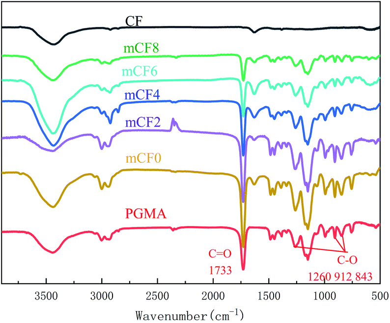
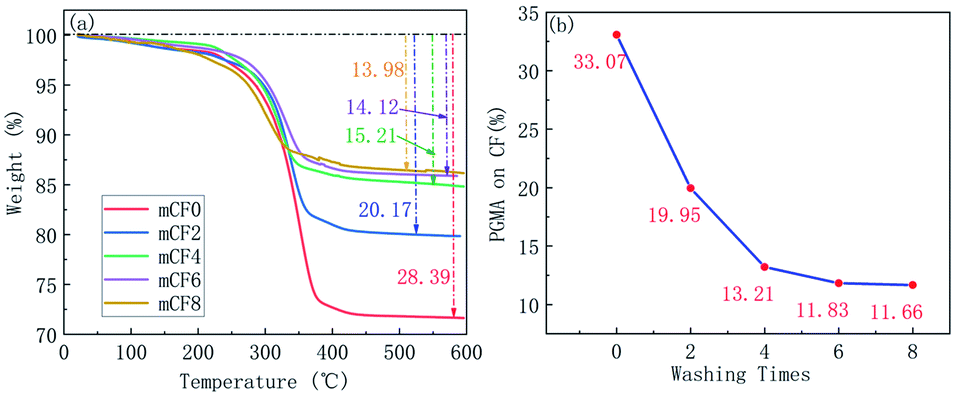
To examine the conjugation between the CF and PGMA, a washing step was conducted by using THF that is a good solvent for PGMA washing,34 thus the PGMA coated on the surface of CF would be dissolved in THF. The samples of mCF were washed by THF for multiple times, the unwashed PGMA was analysed by FT-IR, TGA and SEM. Fig. 1 showed the FT-IR spectra for an mCF sample with different washing times. Characteristic peaks of PGMA appeared on the mCF surface, which included a signal for the CO bond at 1733 cm−1 and others corresponding to the epoxy group (C–O) at 1260, 912 and 843 cm−1. It can be clearly seen that these characteristic peaks did not appear on the CF surface. Besides, it can be seen from Fig. 1 that with increasing number of washing cycles, the characteristic FT-IR peaks of PGMA on the mCF surface were gradually weakened and reached unchanged after 8 times of the washing. The purpose of the TGA test was to determine the amount of polymer grafted on the CF surface. As shown in Fig. 2, the naïve CF had a good thermal stability with only 3.54% heat loss. The thermal weight loss of mCF changed significantly, and the weight loss was decreased with the washing times increased. Fig. 2(b) summarized the quantification results of TGA, from which the grafting ratio of PGMA on CF surface was determined as 11.66%. Taken above together, it could be seen that the CF samples washed eight times with THF following the electrochemical grafting reaction reached the constant weight. It is reasonable to consider that the non-bounded polymer molecules have been dissolved and washed off, and the polymer molecules remaining on the CF are grafted on the CF surface by chemical bind. To further confirm the presence of PGMA on the CF surface, the samples were subjected to SEM observation. It was shown that the surface of naïve CF was smooth and clean, whereas that of unwashed mCF was rough with polymer deposits scattering and disorderly distributed throughout the mCF surface. After washed eight times with THF, the mCF surface was coated with PGMA evenly distributing with a network structure (Fig. 3).
 |
| | Fig. 1 FT-IR spectra for CF and mCF at different washing times (electrolyte: AlCl3, electrolyte concentration: 0.10 mol L−1, current intensity: 0.02 A, reaction time: 60 min, mCFn, n: washing times). | |
 |
| | Fig. 2 TGA curves and grafting ratio of mCF at different washing times (electrolyte: AlCl3, electrolyte concentration: 0.10 mol L−1, current intensity: 0.02 A, reaction time: 60 min). | |
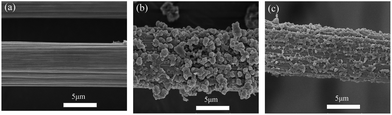 |
| | Fig. 3 SEM images of: (a) a CF, (b) an mCF (unwashed) and (c) an mCF washed eight times (electrolyte: AlCl3, electrolyte concentration: 0.10 mol L−1, current intensity: 0.02 A, reaction time: 60 min). | |
3.2. Selection of electrochemical grafting electrolyte
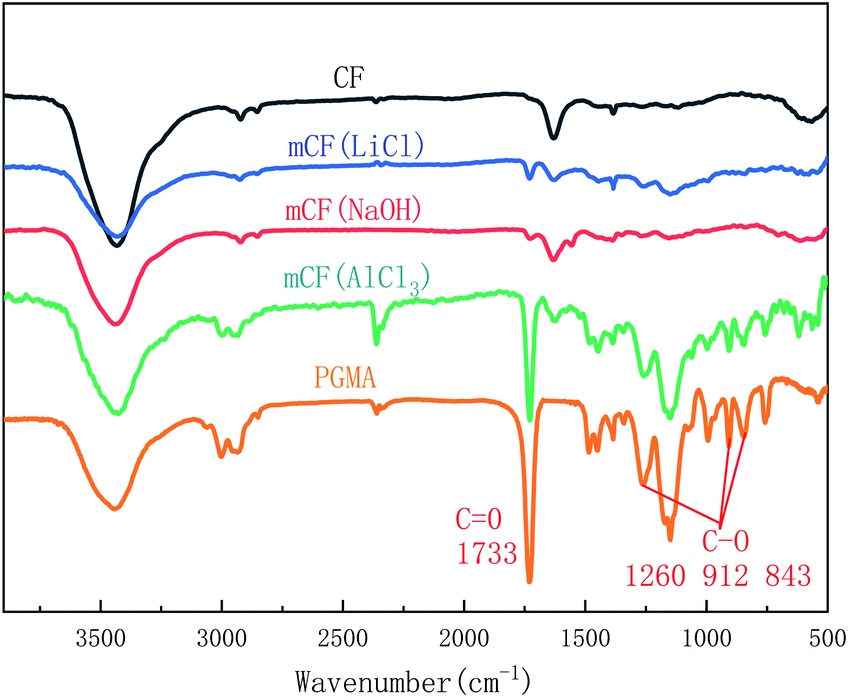
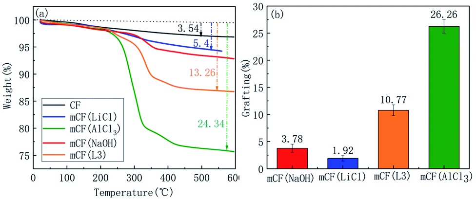
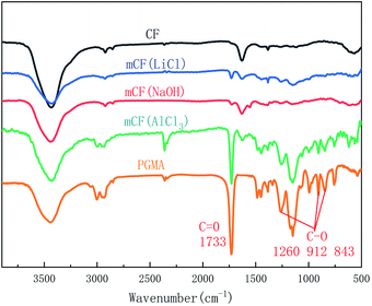
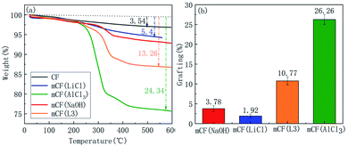
Next, the electrochemical grafting of the CF surface under different electrolyte conditions was investigated. The effects of using different electrolytes, such as AlCl3, LiCl and NaOH, on the electrochemical grafting were investigated experimentally. Fig. 4 showed FT-IR spectra for CF and mCF prepared by using different electrolytes. It was shown that characteristic peaks of PGMA, with a CO signal at 1733 cm−1 and epoxy groups (C–O) signal at 1260, 912 and 843 cm−1, appeared on the surface of CF when the AlCl3 was used in the graft reaction. When LiCl or NaOH was used as electrolyte, there were no obvious characteristic FT-IR peaks of PGMA in the spectra. Fig. 5 showed that mCF prepared using AlCl3 at 0.1 M exhibited higher thermal weight loss, suggesting a higher grafting ratio compared to that of mCF that was prepared using LiCl at 0.1 M or NaOH at 0.1 M as electrolyte. To further elucidate the role of AlCl3, we also prepared a sample using LiCl at 0.3 M (mCF(L3)) to make the reaction solution contain the same number of charges as AlCl3 at 0.1 M. Although the thermal weight loss and grafting ratio of mCF(L3) was higher than that of mCF(LiCl), but still lower than that of mCF (AlCl3). Therefore, the FT-IR and TGA results demonstrated that AlCl3 was the optimal electrolyte for the electrochemical grafting of PGMA on CF. In the electrochemical process, AlCl3 played a role of improving the conductivity of solution and promoting the generation of high active oxygen.
 |
| | Fig. 4 FT-IR spectra of mCF analysed using different electrolytes (electrolyte concentration: 0.10 mol L−1, current intensity: 0.04 A, reaction time: 60 min). | |
 |
| | Fig. 5 TGA curves and grafting ratio of mCF analysed using different electrolytes (electrolyte concentration: 0.10 mol L−1, current intensity: 0.04 A, reaction time: 60 min). | |
3.3. Electrochemical grafting system on CF surface
To determine optimal conditions for electrochemical grafting, grafting ratio at different electrolyte concentrations was investigated. Electrolyte concentration of 0.05, 0.10, 0.15 and 0.20 M, was applied to figure out the relationship between the PGMA grafting ratio and the electrolyte concentration, as shown in Fig. 6. The amount of polymer and the grafting ratio on the CF surface was increased first and then reached a plateau. From the results, it was inferred that the number of grafting reaction sites was proportional to the electrolyte concentration. Therefore, higher concentration of electrolyte would lead to higher grafting ratio22 suggests. When the electrolyte concentration reached a certain level, the degree of anodisation and the number of oxygen-containing functional groups would not change anymore, which resulted in the final grafting ratio.
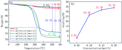 |
| | Fig. 6 TGA curves and weight loss for mCF at different electrolyte concentrations (electrolyte: AlCl3, current intensity: 0.04 A, reaction time: 60 min). | |
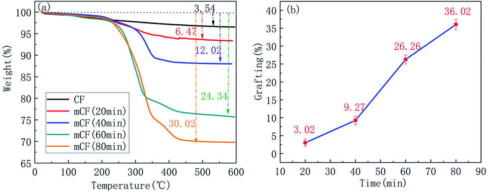
The correlation between grafting ratio and reaction time was also investigated. Fig. 7 showed the TGA curves and grafting ratio for mCF at different reaction times, including 20, 40, 60 and 80 min. Similarly, there is a proportional relationship between reaction time and grafting ratio, which indicated that an increase in the reaction time led to an increase in the number of reaction sites, which ultimately enhanced the grafting ratio, however, the increase rate of the grafting ratio will decrease when the reaction time reached to a certain point; in this case, the degree of anodisation and the number of oxygen-containing functional groups was not changed anymore, which resulted in the final grafting ratio.
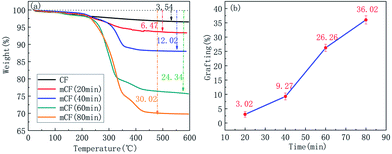 |
| | Fig. 7 TGA curves and weight loss for mCF at different reaction times (electrolyte concentration: 0.10 mol L−1, current intensity: 0.04 A, electrolyte: AlCl3). | |
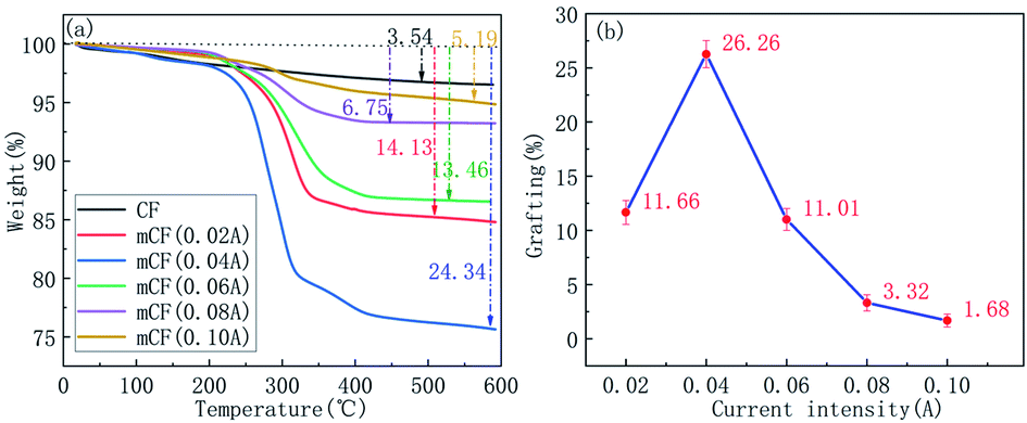
The relationship between grafting ratio and current intensity was also investigated. Fig. 8 showed the TGA curves and grafting ratio for mCF at different current intensities, including 0.02, 0.04, 0.06, 0.08 and 0.10 A. Different from the electrolyte concentration and reaction time, the grafting ratio first increased and then decreased with the current intensity increased. The reason for the grafting ratio reduction was attributable to the occurrence of peroxidation when the current intensity reached to a certain degree.
 |
| | Fig. 8 TGA curves and weight loss for mCF at different current intensities (electrolyte: AlCl3, electrolyte concentration: 0.10 mol L−1, reaction time: 60 min). | |
3.4. Electrochemical grafting of CF with different carboxyl contents
It is reported that the carboxyl-group content was related to current intensity in the anodic oxidation on CF surface.36 Hence CF with different amounts of carboxyl functional groups on surface was prepared and used to investigate the relationship between grafting ratio and carboxyl contents.
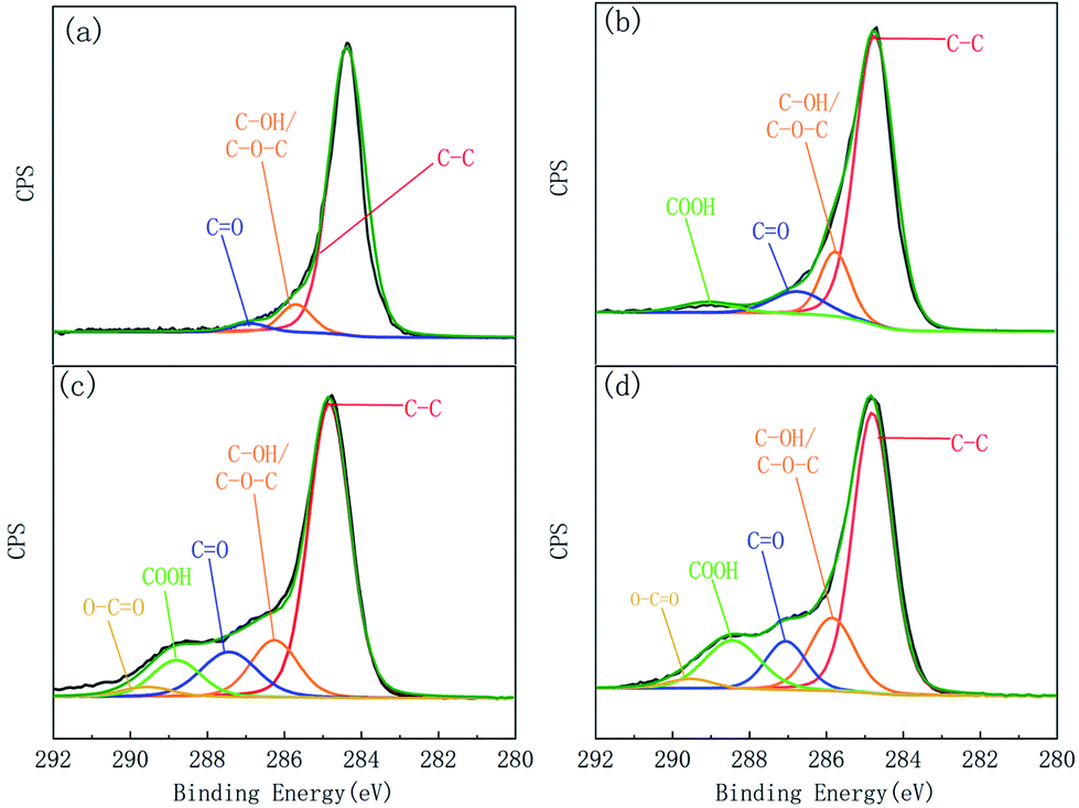
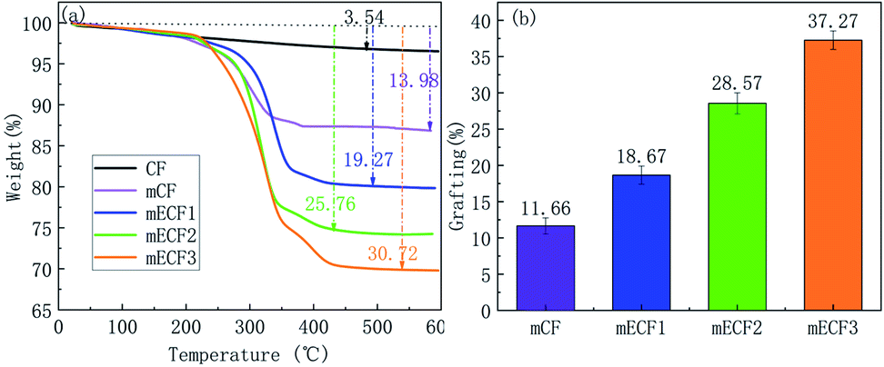
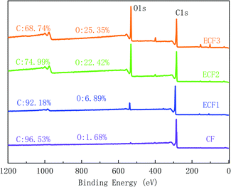
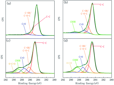
XPS was applied to examine the element content and functional groups on the fibre surfaces, results were given in Table 1 and Fig. 9. The C1s curve of the XPS was fitted to further analyse the changes in the chemical functional groups on the CF surface, as shown in Fig. 10. C1s was divided into five characteristic peaks, including C–C (284.80 eV), C–OH/C–O–C (286.26 eV), CO (287065 eV), COOH (288.40 eV) and O–CO (289.17 eV). ECF1, ECF2, and ECF3 represented anodized CF with different COOH contents, and CF was the control for electrochemical grafting. Fig. 11 presented the TGA curves and grafting ratio for different fibre. It was shown that as the carboxyl content was increased, the thermal weight loss and grafting ratio of the CF surface increased continuously. Compared with naïve CF, the carboxyl content on the surface of ECF1, ECF2 and ECF3 was 3.83%, 9.12% and 13.96%, respectively, and the corresponding grafting ratios were also increased from 11.66% to 18.67%, 28.57% and 37.27%, respectively. Therefore, electrochemical grafting on CF surfaces was proportional to the carboxyl content.
Table 1 Surface element and functional group compositions for CF, ECF1, ECF2 and ECF3
| Samples |
Element composition (%) |
Functional group composition (%) |
| C1s |
O1s |
N1s |
O1s/C1s |
C–C |
C–OH/C–O–C |
CO |
COOH |
O–CO |
| CF |
96.53 |
1.68 |
1.79 |
1.74 |
89.60 |
7.72 |
2.68 |
— |
— |
| ECF1 |
92.18 |
6.89 |
0.65 |
7.47 |
75.28 |
13.07 |
7.82 |
3.83 |
— |
| ECF2 |
74.99 |
22.42 |
2.47 |
29.90 |
61.72 |
13.72 |
12.87 |
9.12 |
2.57 |
| ECF3 |
68.74 |
25.35 |
5.79 |
36.88 |
56.60 |
16.94 |
10.21 |
13.96 |
2.29 |
 |
| | Fig. 9 XPS spectra of CF, ECF1, ECF2 and ECF3. | |
 |
| | Fig. 10 XPS C1s spectra fitted curves for (a) CF, (b) ECF1, (c) ECF2 and (d) ECF3. | |
 |
| | Fig. 11 TGA curves and weight loss for CF with different carboxyl contents (electrolyte: AlCl3, current intensity: 0.02 A, reaction time: 60 min, electrolyte concentration: 0.10 mol L−1). | |
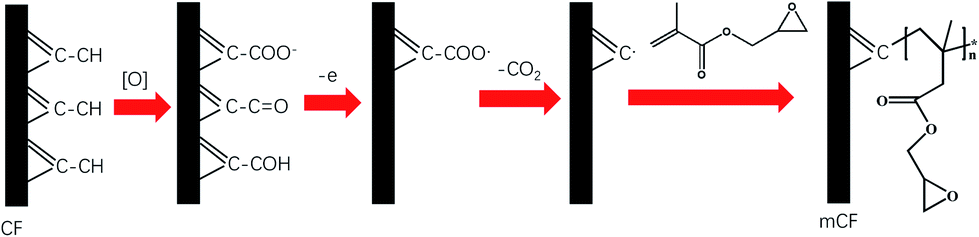
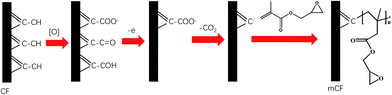
From above analysis, we would suggest that carboxyl functional groups are involved in the electrochemical grafting reaction by a two-step mechanism. The first step is the formation of oxygen-containing functional groups, mainly including –COOH, –OH and CO. The generation of oxygen-containing functional groups on the CF surface is the result of anodic oxidation of CF, the mechanism is described in detail by Qian et al.23 For the reaction of GMA monomer graft polymerisation initiated by COOH, the mechanism can be speculated that is related to the Kolbe reaction.24,37 When CF is used as the anode for the electrical grafting reaction, the COOH on the surface of the CF will first lose electrons and then remove carbon dioxide to generate carbon radicals on the surface of the CF. The carbon radical will attack the carbon–carbon double bond in GMA to initiate the radical polymerisation of GMA monomer, the mechanism is shown in Fig. 12.
 |
| | Fig. 12 Mechanism of electrical grafting on a CF surface. | |
3.5. Interfacial properties of CF composites with different grafting ratios
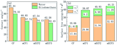
The contact angle test and IFSS test were performed on mCF1, mCF2, and mCF3, the sample information was given in Table 2 to investigate the interfacial properties of CF with different grafting ratios. The contact angle of mCF with ratio was shown in Fig. 13. It was shown that the contact angle decreased from 97.44° to 68.85°, 67.54° and 62.58° for water and from 79.32° to 57.74°, 54.13° and 52.43° for diiodomethane when the grafting ratio was 9.27%, 11.66% and 17.94%. The total surface free energy of the untreated CF was 19.66 mJ m−2, and its dispersion component and polar component was 17.84 and 1.81 mJ m−2, respectively. When the grafting ratio was 9.27%, the dispersion and polar components of surface energy was increased to 29.86 mJ m−2 and 9.2 mJ m−2 respectively, whereas the total surface free energy was increased to 39.07 mJ m−2. The highest surface free energy of mCF3 was 44.21 mJ m−2 with the dispersion components (32.93 mJ m−2) and polar components (11.29 mJ m−2). The increased surface energy would be beneficial to the wettability between the CF and matrix, promoting the comprehensive performance of CF reinforced resin composite. IFSS is one of the most important performances to characterize interface adhesion between CF and epoxy resin, which was obtained from the droplet test and showed in Table 2. The IFSS value of CF, mCF1, mCF2 and mCF3 composites was 39.13 MPa, 68.34 MPa, 72.72 MPa and 78.84 MPa, respectively. Compared with naïve CF, mCF1, mCF2 and mCF3 increased IFSS of the composites by 74.65%, 85.84% and 101.48%. Taken above together, the interfacial properties of mCF composites was improved by the PGMA modification.
Table 2 IFSS of CF, mCF1, mCF2 and mCF3
| Samples |
Grafting of PGMA (%) |
IFSS (MPa) |
Improvements (%) |
| CF |
0 |
39.1 ± 1.3 |
0.00 |
| mCF1 |
9.27 |
68.34 ± 1.1 |
74.65 |
| mCF2 |
11.66 |
72.72 ± 2.0 |
85.84 |
| mCF3 |
17.94 |
78.84 ± 2.3 |
101.48 |
 |
| | Fig. 13 Contact angles and surface free energy of untreated CF and mCF with different grafting ratios (grafting ratio of mCF1: 9.27%, grafting ratio of mCF2: 11.66%, grafting ratio of mCF3: 17.94%). | |
4. Conclusion
In summary, we developed a simple and controllable electrochemical graft polymerisation approach that was able to have GMA polymerised and grafted on CF surface effectively by using AlCl3 as electrolyte and CF as anode. The reaction is possibly involved with a two-step mechanism. The surface modification improved the interfacial properties of CF epoxy composites.
Conflicts of interest
We declare that we do not have any commercial or associative interest that represents a conflict of interest in connection with the work submitted.
Acknowledgements
This work was supported by Ministry of Education of the People's Republic of China (6141A02033233) and State Administration of Science, Technology and Industry for National Defense (JCKY2018110C139).
Notes and references
- Y. Liu and S. Kumar, Polym. Rev., 2012, 52, 234–258 CrossRef CAS.
- Y. Liu, X. Zhang, C. Song, Y. Zhang, Y. Fang, B. Yang and X. Wang, Mater. Des., 2015, 88, 810–819 CrossRef CAS.
- J. J. Li, C. K. Zhu, Z. J. Zhao, P. Khalili, M. Clement, J. F. Tong, X. L. Liu and X. S. Yi, J. Appl. Polym. Sci., 2019, 136, 47801 CrossRef.
- Y. Yang, Y. Pan, Z. Feng and S. Shi, New Carbon Mater., 2014, 29, 161–168 Search PubMed.
- F. A. A. Matias and M. Tubino, J. Air Waste Manage. Assoc., 2001, 51, 962–965 CrossRef CAS PubMed.
- L. Yang, S. Cheng, Y. Ding, X. Zhu, Z. L. Wang and M. Liu, Nano Lett., 2012, 12, 321–325 CrossRef CAS PubMed.
- X. Zhang, X. Fan and C. Yan, et al., ACS Appl. Mater. Interfaces, 2012, 4, 1543–1552 CrossRef CAS PubMed.
- M. Sharma, S. Gao, E. Maeder, H. Sharma, L. Y. Wei and J. Bijwe, Compos. Sci. Technol., 2014, 102, 35–50 CrossRef CAS.
- L. Cui, P. Wang, Y. Zhang, L. Zhang, Y. Chen, L. Wang, L. Liu and X. Guo, RSC Adv., 2017, 7, 42783–42791 RSC.
- Z. Liu, B. Hao and Y. Zhang, RSC Adv., 2015, 5, 40668–40677 RSC.
- Z. Liu, L. Zhang, E. Yu, Z. Ying, Y. Zhang, X. Liu, W. Eli and Y. Zhang, Curr. Org. Chem., 2015, 19, 991–1010 CrossRef CAS.
- E. A. M. Hassan, D. Ge, L. Yang, J. Zhou, M. Liu, M. Yu and S. Zhu, Composites, Part A, 2018, 112, 155–160 CrossRef CAS.
- B. Gao, R. Zhang and C. Wang, Polym. Test., 2016, 56, 192–199 CrossRef CAS.
- B. Gao, J. Zhang, Z. Hao, L. Huo, R. Zhang and L. Shao, Carbon, 2017, 123, 548–557 CrossRef CAS.
- B. Gao, R. Zhang, M. He, C. Wang, L. Liu, L. Zhao, Z. Wen and Z. Ding, Composites, Part A, 2016, 90, 653–661 CrossRef CAS.
- Y. Wang, L. Meng, L. Fan, G. Wu, L. Ma, M. Zhao and Y. Huang, Appl. Surf. Sci., 2016, 362, 341–347 CrossRef CAS.
- Y. Wang, L. Meng, L. Fan, L. Ma, M. Qi, J. Yu and Y. Huang, Appl. Surf. Sci., 2014, 316, 366–372 CrossRef CAS.
- J. Sun, F. Zhao, Y. Yao, Z. Jin, X. Liu and Y. Huang, Appl. Surf. Sci., 2017, 412, 424–435 CrossRef CAS.
- Q. Chang, H. Zhao and R. He, Surf. Interface Anal., 2017, 49, 750–754 CrossRef CAS.
- J. Friedrich, K. Altmann, S. Wettmarshausen and G. Hidde, Plasma Processes Polym., 2017, 14, 1600074 CrossRef.
- Q. Ma, Y. Gu, M. Li, S. Wang and Z. Zhang, Appl. Surf. Sci., 2016, 379, 199–205 CrossRef CAS.
- M. Andideh and M. Esfandeh, Compos. Sci. Technol., 2016, 134, 132–143 CrossRef CAS.
- X. Qian, X. Wang, Q. Ouyang, Y. Chen and Q. Yan, Appl. Surf. Sci., 2012, 259, 238–244 CrossRef CAS.
- D. Belanger and J. Pinson, Chem. Soc. Rev., 2011, 40, 3995–4048 RSC.
- A. Bauer, D. Meinderink, I. Giner, H. Steger, J. Weitl and G. Grundmeier, Surf. Coat. Technol., 2017, 321, 128–135 CrossRef CAS.
- H. Randriamahazaka and J. Ghilane, Electroanalysis, 2016, 28, 13–26 CrossRef CAS.
- S. Gabriel, R. Jerome and C. Jerome, Prog. Polym. Sci., 2010, 35, 113–140 CrossRef CAS.
- B. Lin, R. Sureshkumar and J. L. Kardos, Chem. Eng. Sci., 2001, 56, 6563–6575 CrossRef CAS.
- K.-B. Hung, J. Li, Q. Fan and Z.-H. Chen, Composites, Part A, 2008, 39, 1133–1140 CrossRef.
- S. Shkolnik and C. Barash, Polymer, 1993, 34, 2921–2928 CrossRef CAS.
- G. Shi, X. S. Li, Z. Y. Feng, L. Y. Wu and C. H. Ni, Polym.-Plast. Technol. Eng., 2015, 54, 881–888 CrossRef CAS.
- T. Wang, J. Wang, W. Chen, H. J. Duan, H. B. Xiao, J. P. Wang and J. J. Yang, High Perform. Polym., 2015, 27, 177–182 CrossRef CAS.
- M. S. Broujerdi, M. Masoomi and M. Asgari, J. Reinf. Plast. Compos., 2013, 32, 1675–1684 CrossRef.
- D. Lan, L. Xiong, H. Wanyan, Y. Yuan, Q. Fan, X. Zeng, Y. Chen and Z. Cao, Polym. Polym. Compos., 2017, 25, 113–118 CAS.
- Q. Peng, Y. Li, X. He, H. Lv, P. Hu, Y. Shang, C. Wang, R. Wang, T. Sritharan and S. Du, Compos. Sci. Technol., 2013, 74, 37–42 CrossRef CAS.
- Y. Guo, J. Liu and J. Liang, J. Mater. Sci. Technol., 2005, 21, 371–375 CAS.
- A. Wiebe, T. Gieshoff, S. Mohle, E. Rodrigo, M. Zirbes and S. R. Waldvogel, Angew. Chem., Int. Ed., 2018, 57, 5594–5619 CrossRef CAS PubMed.
|
| This journal is © The Royal Society of Chemistry 2020 |
Click here to see how this site uses Cookies. View our privacy policy here. 
 Open Access Article
 This Open Access Article is licensed under a Creative Commons Attribution-Non Commercial 3.0 Unported Licence
 ,
Ruyu Ruan,
Wenshun Wang
,
Ruyu Ruan,
Wenshun Wang