 Open Access Article
Fundamentals and recent progress relating to the fabrication, functionalization and characterization of mesostructured materials using diverse synthetic methodologies
Soroush Soltani *a,
Nasrin Khanianb,
Umer Rashidc and
Thomas Shean Yaw Choonga
aDepartment of Chemical and Environmental Engineering, Universiti Putra Malaysia, 43400 Selangor, Malaysia. E-mail: soroush.soltaani@gmail.com; Tel: +60 122635051
bDepartment of Physics, Islamic Azad University, Karaj, Iran
cInstitute of Advanced Technology, Universiti Putra Malaysia, 43400 Selangor, Malaysia
First published on 24th April 2020
Abstract
Since 1990 and the invention of the very first generation of ordered mesoporous silica materials, several innovative methodologies have been applied to synthesize, characterize, and modify silica/non-silica mesoporous materials. The growth of the mesoporous materials field has generated significant environmental and economic advantages compared to various other industrial developments. According to the literature, there are several key synthesis approaches and parameters that can affect the structural, textural and morphological characteristics of mesoporous materials. To date, huge attempts have been made to maximize the activities and selectivities of these materials through either the in situ or post-synthesis functionalization of the large interior surface areas and internal mesostructured frameworks in the presence of specific organic/inorganic components. However, the main challenge is to provide good control over the incorporation and distribution of multiple guest components within the mesostructured hosts. Mesostructured materials have received great attention for various applications, such as being used in electronics, medicine, photocatalysis, catalyst supports, catalysis, absorbers, sensors, gas separation, etc. In the current paper, several recent developments have been highlighted and reviewed regarding the fabrication and characterization of siliceous/non-siliceous mesoporous materials via various synthetic approaches. Furthermore, the availability of diverse functionalization methods has been reviewed to provide comprehensive approaches for synthesizing new generations of suitably modified mesoporous materials with superior structural, physicochemical, and textural characteristics.
Introduction
Among all synthesized porous materials, microporous zeolites are known as one of the best, with superior characteristics during various processes. The combination of several unique properties, such as ion exchange capabilities, uniform and stable pore structures, and good thermal and mechanical stabilities, gives them the potential to be widely applied to separation, sorption, catalysis, etc. Over the last few decades, several innovative fabrication methodologies have been applied to enhance the structural and textural characteristics of these zeolites. However, some limitations, such as weaker acid strength and less functionalization capabilities (due to small pore sizes), have encouraged the scientific community to design and synthesize alternative advanced materials. Following the invention of the very first generation of ordered mesoporous silica (OMS) materials, tremendous attention has been paid to the development of new compositions and structures through the synthesis of silica/non-silica mesoporous materials.Recently, diverse synthetic approaches have been proposed for fabricating inorganic mesoporous materials. According to empirical studies, there are several key synthesis approaches and parameters that can affect the structural and morphological characteristics of the final materials, including the properties of the components, chemical ratios, operating times and temperatures, pH values, and type of reactor used (reflux system, or microwave or autoclave assisted techniques). Generally speaking, the synthesis of mesostructured materials can be controlled through altering the surfactant type (ionic or non-ionic) and the interaction mechanism between the template (if employed) and silica components.1,2 M41S silica molecular sieves were initially synthesized under alkaline conditions, where the anionic inorganic species (I−) become stable in the presence of the cationic surfactant (S+) through S+I− strong interactions. Similarly, silica mesostructures could be shaped with an anionic surfactant (S−) under acidic conditions (inorganic species: I+) using the S–I+ approach. SBA materials are typically synthesized in an acidic environment through a ((S0H+)(X−I+)) indirect interaction between the surfactant and positively charged template.3 Another example is HMS materials, which are formed via a (S0I0) neutral interaction between an inorganic component and surfactant. All types of interactions are illustrated in Fig. 1.4 It should be noted that there are other crucial elements, such as the chemical volume, the type of solvent, and the presence of additives (like swelling agents, salts, co-surfactants, and co-solvents), that allow the fine-tuning of the prepared materials.
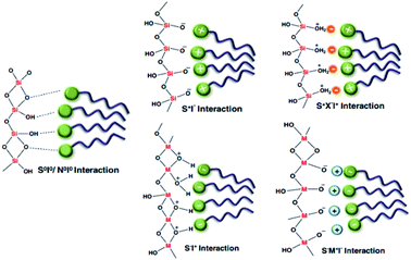 | ||
| Fig. 1 A schematic illustration showing all types of interaction mechanism between surfactant and silica components4 [anionic inorganic species: (I−); cationic inorganic species: (I+); cationic surfactant: (S+); anionic surfactant: (S−)]. Reprinted with permission from ref. 59. Copyright 2011 RSC. | ||
Generally, the fabrication of templated mesostructured materials can be done through the following steps:
(i) The dissolution of template components in the solvent.
(ii) The addition of the silica source under constant stirring.
(iii) Hydrolysis and pre-condensation at a certain reaction temperature using appropriate thermal treatment.
(iv) The recovery of the as-synthesized sample through washing and drying treatments.
(v) The removal of the template using either extraction or calcination techniques.
The extraction approach often remains incomplete and cannot be applied to all surfactants and sources.5 However, it is preferred from cost-effective and environmental perspectives as it allows for the recovery or reuse of templates. The calcination procedure leads to the further condensation of the silica matrix in contrast to the extraction approach. A schematic overview of the soft templating approach via two synthetic methodologies, (a) cooperative self-assembly and (b) a “true” liquid-crystal templating process, for the fabrication of ordered mesoporous materials is demonstrated in Fig. 2.6 During the cooperative self-assembly procedure, inorganic components interact with surfactants motivated by coulombic forces, hydrogen bonding or covalent bonds. At the interface, the inorganic components polymerize and crosslink, and subsequently cooperatively assemble with the surfactants. Throughout the reaction, supportive charge density and surfactant arrangements between the organic and inorganic components affect each other. Therefore, the compositions of organic–inorganic hybrids are different to some degree. Similar charge densities are arranged at the surfactant/inorganic interfaces during the assembly procedure, accordingly resulting in phase separation and restructuring, and finally leading to the development of an ordered three-dimensional structure with the lowest energy. On the other hand, the “true” liquid-crystal templating process is based on true or semi-liquid-crystal mesophase micelles, which are produced using high-concentration surfactants as templates. The condensation of inorganic precursors is enhanced due to restrained growth around the surfactants, leading to the structuring of ceramic-like frameworks. Straight after condensation, the organic templates can be detached.
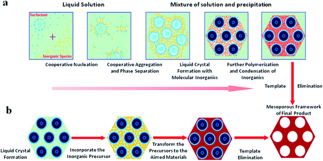 | ||
| Fig. 2 A schematic overview of the soft templating approach via two synthetic methodologies, (a) cooperative self-assembly and (b) ‘‘true’’ liquid-crystal templating processes, for the fabrication of ordered mesoporous materials,6 modified fromref. 7. Reprinted with permission from ref. 6 and 7. Copyright 2013 RSC. | ||
For the synthesis of non-siliceous mesoporous materials, despite the highlighted important elements, the rates of hydrolysis and condensation play crucial roles in controlling the formation of the structure. This is because of the fact that the hydrolysis and condensation processes happen more rapidly for transition metal oxides in comparison with silica materials. So far, comprehensive research has been conducted to allow for the good control of the hydrolysis and condensation processes to avoid phase separations. Indeed, suitable interactions between the surfactant and inorganic components are the result of controlled hydrolysis and condensation procedures. This can occur through increasing the solubility of the metal oxides by adjusting the pH and controlling the amount of water to restrict hydrolysis.8–10 An important point that needs to be taken into consideration is that the thermal stabilities of transition metal oxides are low because of crystallization, phase transitions, and redox reactions. However, there are strategies, such as the extraction of the surfactant as an alternative to calcination, to eliminate unwanted crystallization and avoid structural collapse upon the functionalization of these materials. On the other hand, calcination procedures can be conducted when high crystallinity is a matter of importance. Through the synthesis of mesoporous transition metal oxides, functionalization treatments can be carried out to modify the structural stability.
In the current paper, a brief comparison of zeolites with mesoporous materials has been provided. Attempts have been made to provide an overview of some of the most favourable approaches for the synthesis of siliceous/non-siliceous mesostructured materials. In order to modify siliceous/non-siliceous mesoporous materials, it is highly essential to bridge the knowledge gap between the structure of the materials and their functionality for desired applications. Furthermore, numerous synthetic schemes relating to functionalization are reviewed that allow for better control through the incorporation and, importantly, distribution of functional components within the mesostructured matrix. From this viewpoint, several highly cited papers have been published in this area; these are undoubtedly landmarks and historical contributions when it comes to the development of ordered mesoporous materials and the evolution of this field since its discovery, and progress has been based on these achievements.7,11–16 The authors do not propose that this is the only promising material relating to mesoporous composites, but the key purpose is to stimulate further research into mesoporous materials and to formulate new synthetic procedures and functionalization steps for a wide range of applications.
Mesostructured materials versus zeolites
The discovery of porous materials, particularly zeolites, has generated significant environmental and economic advantages over various other industrial developments. The actual portfolio of microporous architectures, including 201 framework forms, 22 disordered zeolite frameworks and several unknown structures, has been officially recognized by the Structure Commission of the International Zeolite Association.13 Despite the huge variety of zeolite structures, pore diameter has remained a main barrier to chemical reactions involving bulky particles. Therefore, the development of mesoporous materials with pore sizes ranging from 2–50 nm would be a proper answer to this problem. The discovery of ordered mesoporous materials goes back 20 years to the scientists of Mobil;17 this attracted the attention of the scientific community, who were aware of the remarkable characteristics of these mesostructured materials.From a physicochemical point of view, mesoporous materials cannot be distinguished from zeolites, however, these materials should be strictly linked to microstructured materials. The fabrication of mesoporous materials can be considered as a development from zeolites. In the process of the crystallization of microporous materials, organic molecules, which are called templates, hydrate inorganic cations to form three dimensional zeolite architectures. Then, template removal takes place based on chemical extraction or calcination to form microstructures with pore sizes of less than 1 nm. In the case of mesoporous materials, amphiphilic surfactant molecules of various natures (cationic, anionic, non-ionic) containing a hydrophilic polar head play a crucial role in the formation of micelles with different shapes (such as bi-layers, spheres or rods) in the presence of a polar medium.18 The shape of the micelles can be varied by varying the ratio of surfactant molecules to polar chains. It should be noted that the final product possesses the real shape and diameter of the mesoporous architecture.
On the other hand, the low thermal or hydrothermal stabilities and acid strengths of mesostructured materials are still the main barriers preventing their industrial application in comparison with zeolites. Generally speaking, the lack of these properties is related to their amorphous natures. However, these critical issues can be eliminated through various post-functionalization treatments. These can be performed using metal and non-metal elements in the reaction mixture, resulting in the homogeneous dispersal of heteroatoms. In this approach, acid strength can be controlled through the incorporation of monomeric species of Al, such as NaAlO2, Al(i-PrO)3 and Al2(SO4)3, into the amorphous walls, however, dealumination may be enhanced by reducing the SiO2/Al2O3 molar ratio.19,20
Nevertheless, a removal process involving calcination or ion exchange may lead to the formation of both Lewis and Brønsted acid types; however, these Brønsted sites are not comparable with those present in zeolite structures in terms of strength. The acid strengths of mesostructured materials were examined via the pyridine adsorption–desorption technique using Fourier-transform infrared spectroscopy (FTIR). According to the data reported in Table 1, zeolite beta contains the highest concentration of both Lewis and Brønsted acid sites compared with mesoporous silica alumina (MSA), amorphous microporous silica-alumina (ERS-8), and MCM-41.21
| Acid strength (μmol g−1) | |||||||
|---|---|---|---|---|---|---|---|
| Material | Si/Al | Weak | Medium | Strong | |||
| Lewis | Brønsted | Lewis | Brønsted | Lewis | Brønsted | ||
| Zeolite beta | 11 | 117 | 86 | 12 | 69 | 211 | 125 |
| MCM-41 | 19 | 45 | 83 | 41 | 20 | 87 | 17 |
| MSA | 50 | 17 | 23 | 7 | 14 | 77 | 10 |
| ERS-8 | 50 | 15 | 21 | 20 | 17 | 73 | 0 |
The innovation of mesoporous materials has led to new research interest in employing nanosized mesoporous materials, due to their possession of remarkable physical properties for a wide range of prospective applications in different industrial fields. These nanoparticular matrices could have high loading capacities and good mass-transfer characteristics because of their extremely large surface areas and flexible and tunable pore structures. The mesoporous structure can be controlled via the sophisticated selection of surfactants or templates. Besides, the pore size can also be controlled by varying the reaction parameters (such as the chemical composition and operating temperature) or adding supporting organic chemicals. Up to know, only a few elements (such as Ge, V, Ti, Fe, B, and Ga) can be accommodated into zeolites, while many more elements (such as Sn, Zr, Ta, Nb, Zn, etc.) can be incorporated into meso-frameworks. Moreover, nanoscale mixed metal oxides can form in the mesopore walls, which is highly impossible in the case of zeolites due to pore diameter limitations.
The surface areas and porosities of synthesized samples can be controlled through varying the calcination temperature. During the post-annealing process, typically the template condenses on a large scale, which leads to the formation of larger pore diameters.22,23
Summary of key mesostructured materials
Silica-based mesoporous materials
Siliceous mesoporous materials are recent developments in the field of nanotechnology, possessing mesoporous silica architecture. The most common classes of mesostructured materials are Mobil Composition of Matter (or Mobil Crystalline Materials, MCM) and Santa Barbara Amorphous (SBA). The very first generation of mesostructured silica was synthesized in 1970 and went almost unnoticed. Research continued into mesoporous architectures and, later, MCM was fabricated at Mobil Corporation laboratories. Six years later, researchers at the University of California, Santa Barbara successfully synthesized mesostructured silica nanoparticles (MSNs) with hexagonal arrays of pores possessing much larger pore diameters, ranging from 4 nm to 30 nm; this was named SBA-15.The very first reported silica mesophase material was M41S, which is known as an MCM and is in the mesoporous range. It was initially synthesized by Mobil researchers in 1992 through self-assembly with a surfactant as a template to form SiO2 mesoporous materials. M41S materials possess uniform and long-range porosity with pore walls of amorphous silica. M41S materials can be classified into three major types: MCM-41 (cubic); MCM-48 (hexagonal); and MCM-50 (rod).10 There are several key factors that greatly influence the formation of M41S materials, such as the kind of surfactant and its chain length, the operating temperature and operating time, the hydrogel structure, and the alkalinity. The mesophase class can be verified via measuring the surfactant packing factor (g factor, see eqn (1) and Fig. 3(a)), which also describes the hydrophobicity and hydrophilicity of the materials:
 | (1) |
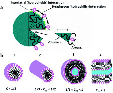 | ||
| Fig. 3 (a) A schematic illustration of surfactant self-assembly demonstrating the critical packing parameters24 and (b) the critical packing factors based on head group area, total volume and the length of the surfactant tail.25 Reprinted with permission from ref. 24 and 25. Copyright 2011 and 2016 respectively MDPI. | ||
From a classical micelle chemistry point of view, a mesostructure can be formed only if the g value goes above a critical value. In this regard, spherical architecture can be obtained in the presence of polar head groups with large surface area, and a rod structure can occur due to the tight aggregation of polar head groups. However, by changing the g factor using different reaction conditions, the ordering of the materials will be affected (see Fig. 3(b)). In general, for packing factors of 1/3, 1/2, 1/2–2/3, and 1, the mesophase can involve cubic (Pm3n), hexagonal (P6m), cubic (la3d), and rod structures, respectively.
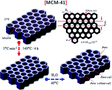 | ||
| Fig. 4 A schematic illustration of the hexagonally shaped MCM-41.28 Reprinted with permission from ref. 28. Copyright 2019 Elsevier. | ||
For conventional MCM-41 materials, the pore diameters vary between 1.5 and 20 nm, where larger pore diameters can be formed in the presence of an excess amount of swelling agent. The occurrence of narrow pore walls in the MCM-41 architecture is the main reason for its low thermal, hydrothermal, and chemical stabilities.29,30 However, attempts have been made to maximize the stability of this material either via the in situ doping of numerous salts or post-functionalization treatments.16
![[thin space (1/6-em)]](https://www.rsc.org/images/entities/char_2009.gif) :
:![[thin space (1/6-em)]](https://www.rsc.org/images/entities/char_2009.gif) silica ratios greater than 1. Cubic MCM-48 material possesses similar textural properties to MCM-41; it also has narrow pore walls, leading to similar limitations. A notable structural characteristic of the MCM-48 material is its three-dimensional bi-continuous pore structure.31 In comparison with one-dimensional systems, the three-dimensional network brings about several advantages relating to separation and catalysis systems, significantly reducing diffusion limitations.
silica ratios greater than 1. Cubic MCM-48 material possesses similar textural properties to MCM-41; it also has narrow pore walls, leading to similar limitations. A notable structural characteristic of the MCM-48 material is its three-dimensional bi-continuous pore structure.31 In comparison with one-dimensional systems, the three-dimensional network brings about several advantages relating to separation and catalysis systems, significantly reducing diffusion limitations.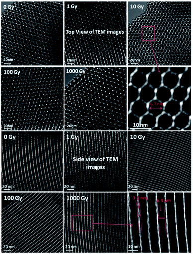 | ||
| Fig. 5 HRTEM images of SBA-15 from the top, with the honeycomb-like mesoporous morphology formation visible, and the side, with the highly parallel, homogeneous pores and channel-like structure visible. Reprinted with permission from ref. 35. Copyright 2018 ACS Nano. | ||
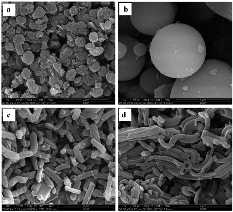
It is worth mentioning that SBA-15 possesses a highly stable internal architecture of mesopores due to its highly hydrophobic nature.36 Through varying the lengths of the copolymer blocks, the internal stability and pore wall thickness can be tuned.37 However, there are other parameters that directly or indirectly affect the morphologies and general characteristics of SBA-15 materials, such as the operating temperature, pH value, and kind of additives used (like salts, co-surfactants, and swelling agents). Up to now, a large variety of morphologies have been reported for SBA-15, consisting of platelets, spheres, and rods. Fig. 6 displays scanning electron microscopy (SEM) images of a few SBA-15 morphologies. Moreover, due to their desirable characteristics, SBA-15 materials have high potential to be introduced as templates for the fabrication of carbon replicates and nanowires using different metals.38
SBA-16 materials can be synthesized in powder form or deposited as films on different substrates using inexpensive and eco-friendly systems. The performance of SBA-16 can be highly improved through its functionalization with various organic or hetero-element groups through either in situ or post-modification approaches.
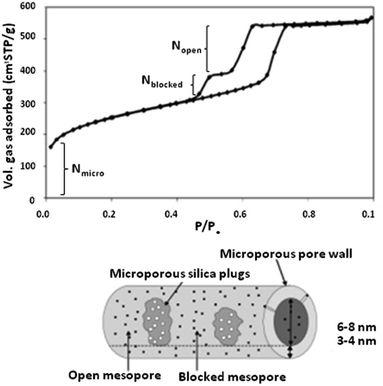 | ||
| Fig. 7 An N2 sorption isotherm of a typical PHTS material.48 Reprinted with permission from ref. 48. Copyright 2002 RSC. | ||
To date, various morphologies of PHTS are known and have been reported. According to the literature, different morphologies can be shaped via tuning the stirring temperature and concentration of tetraethylorthosilicate (TEOS) used in the synthesis procedure. For instance, a high stirring temperature leads to the formation of spherical morphology, while low TEOS amounts and stirring temperatures lead to smooth rods.49,50
The functionalization of PHTS can be performed via introducing catalytically active elements. In this procedure, metal particles can be dispersed on the surface of PHTS using different methods (such as molecular designed dispersion (MDD)), followed by post-calcination. By cautiously choosing the right method, and tuning the size of the nanoparticles and the applied temperature, the active elements can be selectively positioned either (i) in the plugged sections, (ii) in the pores, (iii) on the surfaces of open pores, or (iv) in the silica walls.
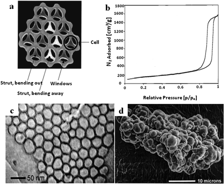 | ||
| Fig. 8 (a) A schematic cross-section diagram of the strut-like structure of MCF. (b) The N2 sorption isotherm of MCF. (c) A TEM image of MCF at high magnification. (d) An SEM image of MCF with cauliflower-type morphology.56 Reprinted with permission from ref. 56. Copyright 2000 American Chemical Society. | ||
The structural characteristics, morphologies and particle sizes of MCF can be controlled through adjusting the synthesis conditions and methods, such as the operating temperature, pH value, and doping of some additives.52–54 The functionalization of MCF materials can be performed using either in situ or post-modification methods to enhance their capabilities.55 Having a larger pore structure increases mass transfer and also increases the chances of large molecules accessing the mesopore channels, which is beneficial for various applications, such as separation, sorption, catalysis, etc.
 | ||
| Fig. 9 (a–d) TEM micrographs of MSU-1, MSU-2, MSU-3, and MSU-4, respectively, with noticeable core–shell structures and mesoporous shells, as evidently highlighted by the higher contrast of the core.59 Reprinted with permission from ref. 59. Copyright 2011 RSC. | ||
Because of the fact that the synthesis process takes place in a neutral (non-acidic) medium, there is neutral contact between the inorganic material and surfactant of the type S0I0, which significantly eases the separation of the surfactant. In this regard, the synthesis process can be done in a more cost-effective manner due to the greater recycling yield of the surfactant after the separation step. Similar to all mesoporous templated materials, the morphological and structural features of MSU could be adjusted via tuning the synthesis conditions and methods, such as the operating temperature, pH value, and doping of some additives.60–62
The DLCT procedure can be used for the fabrication of mesostructured silica and aluminosilicates. Alkylene oxide segments present in the surfactant interact with inorganic ions, resulting in the direct formation of mesoporous silica. This interaction allows for the smooth diffusion of heteroatoms through the silica framework. According to reports, as well as aluminum, noble and base metal ions (such as Pt, Ru, Rh, Ni, Co, Ag, and Cu) can be incorporated into mesostructured silica and aluminosilicates.64–68
It is worth mentioning that the characteristics, especially the acid strengths of the sites, of DLCT aluminosilicates highly depend on the Si![[thin space (1/6-em)]](https://www.rsc.org/images/entities/char_2009.gif) :
:![[thin space (1/6-em)]](https://www.rsc.org/images/entities/char_2009.gif) Al ratio, however, the acid strengths at all Si
Al ratio, however, the acid strengths at all Si![[thin space (1/6-em)]](https://www.rsc.org/images/entities/char_2009.gif) :
:![[thin space (1/6-em)]](https://www.rsc.org/images/entities/char_2009.gif) Al ratios are greater than in MCM-41 materials. This characteristic is a matter of interest in catalysis, where a requirement is the presence of medium acid strength.
Al ratios are greater than in MCM-41 materials. This characteristic is a matter of interest in catalysis, where a requirement is the presence of medium acid strength.
Non-silica based mesoporous materials
Surfactant templating methodologies have been used to synthesize non-silica based mesostructured materials since 1993. To date, several species of non-siliceous mesostructured solids have become known, consisting of metal oxide, phosphate, and sulphide based materials.69 Non-siliceous mesostructured materials are synthesized under a large range of reaction conditions in the presence of surfactants of different natures (ionic, cationic, geminal, or neutral). These materials possess unique characteristics, including tolerating diverse fabrication conditions, and having pore diameter (ranging from 2 nm to 10 nm) and framework structure flexibility, making them applicable to various application fields. It has been stated that the oxidation states of transition metal ions have a great impact on composite mesoporous materials.70,71One-dimensional mesoporous anatase TiO2 nanocrystals were fabricated using carbon nanotubes (CNTs) as a pore-forming agent.72 The synthesized mesoporous TiO2 possessed nanoscale and sub-microscale components with a large surface area of 102.1 m2 g−1 and a pore diameter of 12 nm. In other research, Du et al. synthesized two-dimensional hexagonal (p6mm) ordered mesoporous TiO2 using colloidal crystals as a pore-forming agent.73 The synthesized ordered mesoporous TiO2 possessed unified periodic macropore channels and a large specific surface area and pore diameter of 256 m2 g−1 and 4.9 nm, respectively. As shown in Fig. 10, the existence of unified periodic macropores reduced the length of the mesoporous matrix and improved the specific surface area of the synthesized material. Furthermore, graphene was also added to the ordered macro-mesoporous TiO2 structure to avoid the recombination of charge in the film because of its exceptional electrical characteristics. In other research, Lin Chen et al.74 utilized TiCl4 and Ti(OBu)4 as titania resources in the presence of P123 as a template to fabricate three-dimensional mesoporous titanium dioxide using the EISA method.
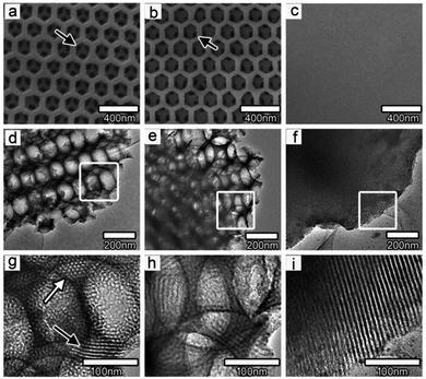 | ||
| Fig. 10 TEM and SEM images of (a, d, g) macro-mesoporous TiO2 film, (b, e, h) TiO2 film with graphene, and (c, f, i) pure mesoporous TiO2 film. (a, b) The black arrows point out the unified channels between the macropores in the film, while (g) the white and black arrows indicate the mesopores contained in the macropore walls.73 Reprinted with permission from ref. 73. Copyright 2011 American Chemical Society. | ||
With the EISA technique, micelles are formed through solvent evaporation, followed by hydrolysis and condensation to provide strong interactions between the template and inorganic titania.75 As the framework is formed, such a slight thermal procedure will play a role in strengthening the network followed by template extraction via post-calcination treatment. An important point that needs to be taken into consideration is that uncontrolled thermal and calcination treatments may cause phase transformation and the collapse of the mesostructured framework.76,77
Titania materials can be attained in bulk form, as nanoparticles, or as films on various substrate with two-dimensional, three-dimensional, and hierarchical structures.78 Like mesoporous silica materials, the structural characteristics, morphologies and particle sizes of titania materials can be controlled through adjusting the synthesis conditions and methods, such as the operating temperature, calcination temperature, aging time and pH value.79 In order to modify the characteristics of mesoporous titania, the functionalization of materials with guest species, like ions, nanoparticles, organic and inorganic molecules, can take place through either in situ or post-treatment methods. Fig. 11 displays schematic representations of the synthesis of mesoporous titania films via either in situ or post-synthesis methods.80 It has been frequently reported that functionalization through post-synthesis techniques fails to regulate the deposition of foreign particles into the mesostructured framework, resulting in a non-uniform distribution in the titania mesoporous material. Moreover, the existence of excess amounts of these particles may block mesopore channels and highly reduce surface areas. The in situ method is a promising method, which allows for the high dispersion of guest particles and eliminates crystal growth, the non-uniform distribution of particles, phase transformations, and pore blockages.
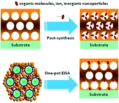 | ||
| Fig. 11 Schematic representations of the synthesis of mesoporous titania films via either in situ or post-synthesis methods.80 Reprinted with permission from ref. 80. Copyright 2011 Elsevier. | ||
Titania nanotubes are another species of TMO material that have received great attention for various applications, such as in electronics, medicine, photocatalysis, catalyst supports, absorbers, sensors, etc. Mesostructured titania nanotubes are typically synthesized in the presence of sodium hydroxide using template-free hydrothermal and microwave assisted methods.81–84 These materials possess open-ended pores, easing the accessibility of reactants to inner pores.
Other than the primary successful route for the fabrication of mesoporous titania, several mesostructured metal oxides and mixed metal oxides have been fabricated via hydrogen-bonding, electrostatic mediation, van der Waals, and covalent interactions between template components and metal particles.85,86 For example, perfect templated zirconium dioxide (ZrO2) nano-disks were synthesized via self-assembly, using Zr(OC4H9)4 as a precursor and dodecylbenzenesulfonic acid (DBSA) as a template (see Fig. 12).87
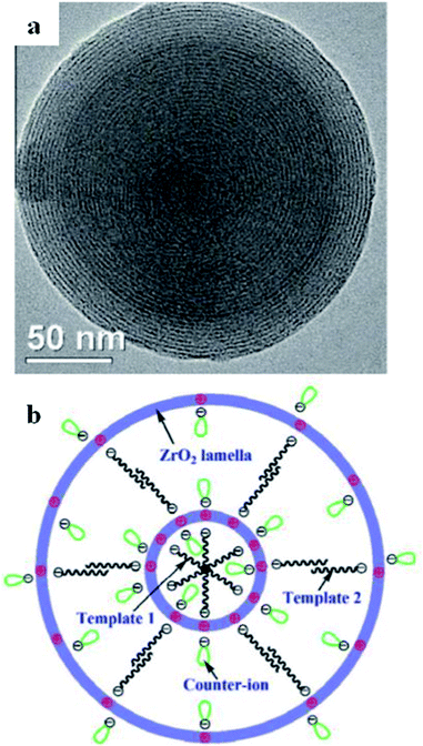 | ||
| Fig. 12 (a) An ideal DBSA-templated ZrO2 multi-ring nanodisk self-assembled at 21 °C with Cl− counter-ions, and (b) the projected structural form of the self-assembled ZrO2 nanodisks with altered counter-ions.87 Reprinted with permission from ref. 87. Copyright 2011 Elsevier. | ||
In one of our research works, polymeric mesoporous carbon@zinc core–shell spheres were synthesized using a hydrothermal-assisted method in the presence of PEG as the surfactant and D-glucose as the template.88 In this study, the effects of different zinc concentrations and calcination temperatures on the structural and textural properties of the synthesized samples were examined and are presented in Table 2. The average crystallite size and pore size diameter were increased from 53.26 to 70.36 nm and from 3.45 to 4.63 nm, respectively, upon raising the calcination temperature from 600 °C to 900 °C, however, the specific surface area significantly declined from 396.56 to 174.87 m2 g−1. It was clearly seen that with an increase in the calcination temperature to 900 °C, the reflection peaks shifted toward higher 2θ angles. This can be attributed to structural shrinkage as a consequence of greater template carbonization. At very high calcination temperatures, D-glucose particles might severely decompose and then collapse, resulting in deformations of the template where ZnO nanoparticles were going to be placed. Furthermore, the shell thickness of the mesoporous carbon@zinc core–shell spheres changed from around 5 nm to 75 nm at different zinc concentrations (2–8 mmol). Similarly, nanocrystalline mesoporous mixed metal oxide (carbon@CuO–ZnO) spheres were hydrothermally fabricated.89 The effects of different Cu![[thin space (1/6-em)]](https://www.rsc.org/images/entities/char_2009.gif) :
:![[thin space (1/6-em)]](https://www.rsc.org/images/entities/char_2009.gif) Zn ratios (0.5, 0.75, and 1.0) on the textural properties were examined; upon raising the metal ratio, the surface area was enhanced (419.13, 477.54, and 517.03 m2 g−1) while the pore size decreased (3.35, 3.11, and 2.88 nm). In another research work, polymeric mesoporous mixed metal oxides (ZnAl2O4) with different Al/(Zn + Al) molar ratios (0.5, 0.75, and 1.0) were hydrothermally synthesized.90 Similarly, upon loading higher metal molar ratios, the surface area increased (414.27–440.38 m2 g−1) while the average pore diameter (3.40–3.10 nm) and average crystallite size (55.92–43.66 nm) decreased.
Zn ratios (0.5, 0.75, and 1.0) on the textural properties were examined; upon raising the metal ratio, the surface area was enhanced (419.13, 477.54, and 517.03 m2 g−1) while the pore size decreased (3.35, 3.11, and 2.88 nm). In another research work, polymeric mesoporous mixed metal oxides (ZnAl2O4) with different Al/(Zn + Al) molar ratios (0.5, 0.75, and 1.0) were hydrothermally synthesized.90 Similarly, upon loading higher metal molar ratios, the surface area increased (414.27–440.38 m2 g−1) while the average pore diameter (3.40–3.10 nm) and average crystallite size (55.92–43.66 nm) decreased.
| Sample | SBETa | Pore diameterb | Total pore volumec | Average crystallite sized |
|---|---|---|---|---|
| a Specific surface areas (m2 g−1) were obtained using the Brunauer–Emmett–Teller (BET) method.b Average pore sizes (nm) were calculated from N2 desorption branches using the BJH model.c Total pore volumes (cm3 g−1) were calculated at P/Po = 0.99 from the N2 adsorption isotherms.d Average crystallite sizes (nm) were calculated from the value of the FWHM of the (101) diffraction peak using the Scherrer equation. | ||||
| Zinc 2 mmol | 126.51 | 4.60 | 0.20 | 60.81 |
| Zinc 4 mmol | 216.03 | 4.56 | 0.22 | 57.28 |
| Zinc 6 mmol | 345.63 | 3.52 | 0.26 | 53.26 |
| Zinc 8 mmol | 290.26 | 3.91 | 0.24 | 49.56 |
| 600 °C | 396.56 | 3.45 | 0.31 | 53.26 |
| 700 °C | 345.63 | 3.52 | 0.26 | 57.12 |
| 800 °C | 209.03 | 4.59 | 0.22 | 60.82 |
| 900 °C | 174.87 | 4.63 | 0.20 | 70.36 |
The strategy for the formation of C@Zn core–shell solids using a PEG-assisted method is displayed in Fig. 13. The formation and development of C@Zn core–shell solid spheres occurred over the following sequence of reaction steps in a Teflon-lined stainless-steel autoclave:88
| nZn(NO3) → nZn2+ + [NO3]2n | (I) |
| nZn2+ + OH− → ZnOH− | (II) |
| ZnOH− → ZnOH + e | (III) |
| ZnOH + OH− → Zn(OH)2 + e | (IV) |
| [Zn(OH)2]n + nPEG → [Zn(OH)2-PEG]n | (V) |
 | ||
| Fig. 13 A schematic representation of the formation of C@Zn using a PEG-assisted method, including an SEM image of a C@Zn solid sphere that was hydrothermally synthesized at 200 °C for 24 h and post-annealed at 600 °C for 4 h.88 Reprinted with permission from ref. 88. Copyright 2016 Elsevier. | ||
Under hydrothermal reaction conditions (high temperature and high pressure), D-glucose, as the carbon source, decomposed into gaseous compounds such as CO, CO2, and H2. These compounds further acted as templates for building primary carbon spheres. Along with the formation of carbonaceous spheres, zinc nitrate decomposed to Zn2+ cations, which electrostatically interacted with hydrophilic groups (–OH) to form Zn(OH)2 (steps (I)–(III)). As time went by, a complex compound of [Zn(OH)2]n formed as neighbouring Zn(OH)2 entities interacted with each other via their hydrophilic groups (step (IV)). Next, the oxygen atoms from the PEG components basically adsorbed due to the positive charge of Zn(OH)2 via hydrogen bonding to form chains of [Zn(OH)2-PEG]n (step (V)). Basically, PEG molecules were adsorbed on the surfaces of the particles as a result of water-miscible long-range bonding, inhibiting the adhesion and accumulation of metal particles. As the reaction temperature reached 180 °C inside the autoclave, Zn(OH)2 was transformed to zinc oxide (ZnO), which further interacted with and was incorporated into the carbonaceous cores, with a shell of ZnO nanoparticles placed in the exterior layer of the carbon sphere wall. Next, the post-annealing process proceeded to transform the core–shell architecture into a mesostructured one under a N2 atmosphere; this eventually resulted in the formation of a smooth ZnO shell around a carbon core.
In comparison with silica-based materials, very little attention has been paid to non-silica-based mesostructured composites due to the following reasons:4
(i) Transition metal oxides show high reactivity toward hydrolysis and condensation reactions, which results in unrestrained phase separation between inorganic and organic species.
(ii) The crystallization and phase transitions of these oxides often result in a breakdown in structural integrity.
(iii) The synthetic procedures are highly sensitive to some external elements, making it impossible to reproduce results in many cases.
Functionalization of the macroscopic characteristics of mesoporous materials
Functionalization of mesoporous materials can be performed via either in situ or post-modification methods to enhance their capabilities for the desired applications.In situ functionalization approaches
The very first advantage of one-pot modification is its simplicity, as the incorporation of functional components into mesopore channels occurs via just one synthetic procedure. On the other hand, functional species must only be distributed to the desired regions and must not interrupt the process of mesophase self-assembly. This fact explains some limitations relating to this method in aqueous solutions, as hydrophobic functional components tend to interact with organic templates in the meso-channels, hydrophilic functional components tend to be incorporated into the inorganic framework walls, and amphiphilic functional components tend to be distributed at interface sites. Therefore, the choice of functional component plays a crucial role in the choice of one-pot modification route used in an aqueous solution system.
The co-condensation of mixed metal oxides into mesopore channels is a known synthetic route for the functionalization of mesostructured materials. A schematic representation showing a co-condensation method to incorporate a functional component (R) into mesoporous inorganic materials via direct co-assembly is illustrated in Fig. 14.91 The incorporation of Al into mesoporous silica can be taken as an example, as Lewis or Brønsted acid functional components can be incorporated into inorganic meso-channels. Also, the co-condensation of mesoporous silica with transition metal oxides (such as V, Ti, and Cr) and rare-earth elements (such as Tb and Eu) has been widely reported. The solution pH conditions should be chosen according to the template used. For instance, slow precipitation leads to the formation of films, fibers and monoliths, while quick co-condensation leads to the formation of powders. Generally, mesoporous mixed metal oxide materials should be synthesized under basic pH conditions to enable an effective co-condensation procedure with higher heteroatom loading into the silica channels.
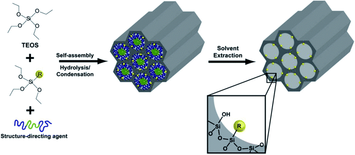 | ||
| Fig. 14 A schematic representation of a co-condensation method used to incorporate a functional component (R) into mesoporous inorganic materials via direct co-assembly.91 Reprinted with permission from ref. 91. Copyright 2009 Elsevier. | ||
Another category of functionalized mesoporous materials is referred to as periodic mesoporous organosilicas (PMOs), which are considered to be innovative organic/inorganic hybrid nanocomposites. PMOs are typically synthesized through hydrolysis and condensation in the presence of organosilica sources using a suitable template and a self-assembly method. As highly ordered mesostructured materials, PMOs possess hexagonal and cubic structures with high surface areas.
Four proposed routes for the fabrication of PMOs with organic species in their frameworks are as follows:12
(i) The use of single-bridged organosilica precursors.
(ii) The use of dual bridged organosilica precursors containing diverse functional species.
(iii) The presence of the dangling organic species in the bridged organosilica and silica precursors.
(iv) The post-synthetic functionalization of bridged organic species of the synthesized PMO.
A schematic representation of the four proposed routes for the fabrication of PMOs with organic species in their frameworks is demonstrated in Fig. 15. The main advantage of PMOs is the uniform hybridization of organic and inorganic components ((R′O)3Si-R-Si(OR′)3 (R′ = methyl or ethyl; R = the bridged organic groups)) as a bridge within the mesopore walls of silica.92 Through the organic functionalization of PMO materials, it is possible to highly control surface characteristics such as hydrophobicity and hydrophilicity, and the incorporation of foreign particles. Along with this, there is the inherent potential to protect the mesopore channels from the accumulation of guest particles.93 In contrast to other siliceous analogs, PMOs possess less fragility and greater hydrophobicity.94 To date, significant efforts have been made to achieve great advancements in the fabrication of functionalized PMOs for certain applications, such as in gas separation, electronic devices, and catalysis.12
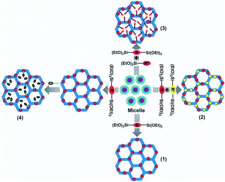 | ||
| Fig. 15 A schematic representation of the four proposed routes used for the fabrication of PMOs with organic species in their frameworks: (1) a single-bridged organosilica precursor; (2) dual-bridged organosilica precursors with dissimilar functional groups; (3) bridged organosilica and silica precursors with dangling organic groups; and (4) secondary amendment via a chemical procedure involving a bridged organic moiety following the fabrication of the PMO.12 Reprinted with permission from ref. 12. Copyright 2013 Springer Nature. | ||
Shinji Inagaki et al.95 reported the fabrication of an ordered PMO material, using a benzene-silica hybrid component in the presence of a surfactant. Fig. 16 illustrates a simulated model of the mesoporous benzene-silica with crystal-like pore walls. Benzene chains are arranged in a loop around the pores, associated on two sides with silicate chains, while Si–OH groups are incorporated into silicate at the surface. However, benzene layers with a hydrophobic nature and silicate layers with a hydrophilic nature are arranged along the channels. The orange, red, white, and yellow colours represent silicon, oxygen, carbon, and hydrogen, respectively.
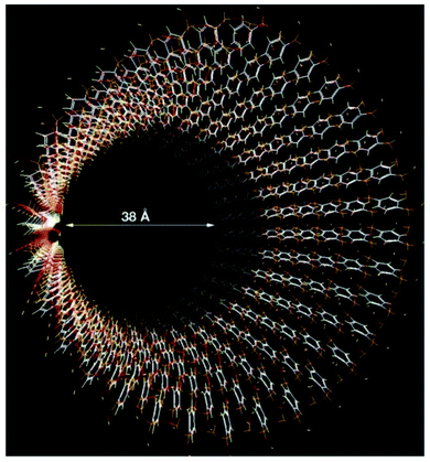 | ||
| Fig. 16 A simulated model of mesoporous benzene-silica with crystal-like pore walls. Benzene rings are associated in a circle just around the pores, associated on both sides with silicate chains. Silicate was joined to silanol (Si–OH) at the surface. The hydrophilic silicate layers and hydrophobic benzene layers are arrayed alternately at an interval of 7.6 Å along the channel route; silicon: orange; carbon: white; hydrogen: yellow; oxygen: red.95 Reprinted with permission from ref. 95. Copyright 2002 Springer Nature. | ||
An important point that needs to be taken into consideration is that the hydrophobic/hydrophilic nature and mechanical and chemical properties of these materials can be perfectly tuned via the careful arrangement of the framework organic component numbers and species. For instance, the dual surface modification of mesostructured silica can be performed through the self-assembly and co-condensation of acid functional groups and organosiloxane sources using a block co-polymer template. These materials can be used for catalyzing the esterification of free fatty acid (FFA) to produce biodiesel. The hydrophobicity can be improved via adding hydrophobic organosiloxane species into the mesopore structure to eradicate the presence of molecules of water near the active sites. It is known that the presence of water causes the formation of soap and deactivates catalysts through chemical reactions.96–100 In a research work, Yang et al.101,102 applied the one-pot acid functionalization of phenylene-silica via co-condensation in the presence of 1,4-bis(triethoxysilyl)benzene and (3-mercaptopropyl)-trimethoxysilane using a non-ionic surfactant in an acidic medium. Characterization proved the successful bonding of oxidized species of the mercaptopropyl group (C3H6SO3H) to the silicate mesopore layers (see Fig. 17). The synthesized materials have the great potential to esterify acetic acid in the presence of ethanol.
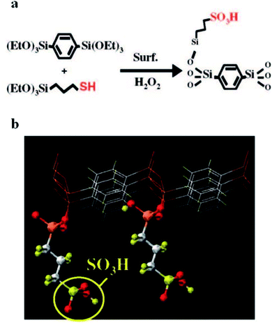 | ||
| Fig. 17 A schematic illustration indicating (a) the in situ fabrication of SO3H-phenylene-silica via co-condensation in the presence of 1,4-bis(triethoxysilyl)benzene and (3-mercaptopropyl)-trimethoxysilane using a non-ionic surfactant in an acidic medium; and (b) a CG image of a functionalized surface with propylsulfonic species.92 Reprinted with permission from ref. 92. Copyright 2008 American Chemical Society. | ||
The introduction of co-assembly/co-condensation approaches is not only applicable to oxidic systems but also to obtaining mesostructured channels of mixed semiconducting materials. These classes of mesostructured semiconductor materials have large specific surface areas of several hundreds of m2 g−1, and the conductivity highly depends on the framework species. The combination of these characteristics makes these materials applicable to photonic, electronic and sensor applications.
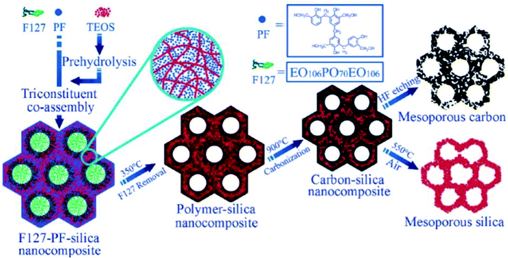 | ||
| Fig. 18 A schematic illustration indicating a synthesis method for the fabrication of mesostructured polymer-silica nanocomposites.103 Reprinted with permission from ref. 103. Copyright 2006 American Chemical Society. | ||
There are other non-covalent functional components, such as conjugated polymers and surfactant-passivated nanoparticles, that can be applied to mesostructured inorganic–organic sites via a co-assembly method. Mesostructured materials can be modified with conjugated polymers for optoelectronic and electronic applications. For instance, hydrophobic sections of block co-polymer silica were combined with hydrophobic conjugated polymer sources, such as poly-[2-methoxy-5-(2′-ethyl-hexyloxy)-1,4-phenylenevinylene], under non-aqueous conditions.104–106 Through controlling the template and solvent components, it is possible to improve the interfacial contact between the conjugated polymer particles and mesostructured network through a co-assembly synthesis method. Similarly, mesostructured materials can be functionalized with surfactant-passivated nanoparticles. Fan H. et al.107 synthesized well-ordered three-dimensional nanocrystalline mesoporous gold nanoparticles through co-assembling hydrophilic nanocrystalline micelles within a silica framework (see Fig. 19). In this case, water was used as an intermediate for the soluble nanocrystals. The dimensions of the cells were tuned via adjusting the sizes of the nanocrystals and/or the chain lengths of the surfactants. Using an excess amount of the cross-linking silica source, co-assembly took place, fabricating an inorganic matrix near the gold nanoparticles with a hydrophobic nature. Non-covalent functional components have high potential to co-assemble, since they are highly compatible with inorganic sources, solvents and template components. These materials have the potential to incorporate via co-assembly into mesostructured matrices and to interact with several self-assembling components in only one synthetic step.
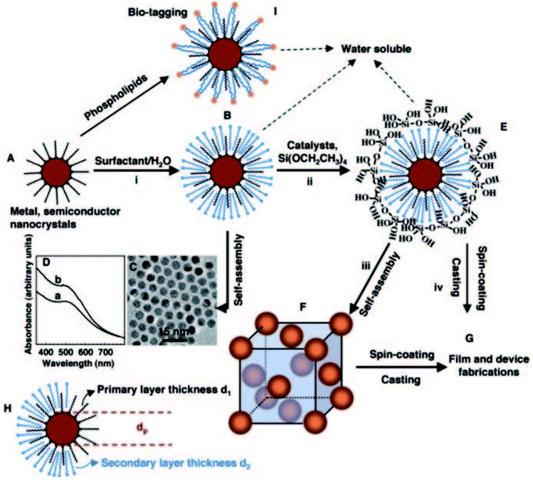 | ||
| Fig. 19 A schematic illustration showing a synthesis method for the fabrication of water-soluble gold nanocrystal micelles and periodically ordered gold nanocrystal/silica mesostructures. (A) Gold nanocrystals were synthesized using 1-dodecanethiol as a stabilizing agent, where heat treatment was applied to additionally narrow the size of the particles. (B) Thiol-stabilized nanocrystals were encapsulated into surfactants via an oil-in-water microemulsion technique to form water-soluble nanocrystal (NC) micelle structures that, after evaporation, (C) self-assemble to form hexagonally ordered NC arrays. (D) The UV-visible spectra of (a) gold nanocrystals in chloroform and (b) gold NC micelles in water. (E) Silicic acid moieties produced through the hydrolysis of TEOS were ordered at the hydrophilic surfactant–water interface of NC micelles, leading to a gold NC/silica mesophase (F) composed of NCs ordered in a periodic face-centered cubic lattice inside a strong silica framework. (G) Under acidic conditions, casting or spin-coating resulted in ordered thin-film NC/silica mesophases. (H) The lattice constant of the NC/silica mesophase was restricted by the nanocrystal size, the primary layer thickness of the alkanethiol, and/or the secondary layer thickness of the surfactant. (I) Lipids or polyethylene glycol surfactants were proposed to prepare biocompatible water-soluble NC micelles for bio-labeling.107 Reprinted with permission from ref. 107. Copyright 2004 The American Association for the Advancement of Science. | ||
Post-synthetic functionalization approaches
Occasionally, one-pot synthetic approaches are not suitable to functionalize mesostructured materials with the desired microscopic characteristics. Post-synthetic modification is an approach in which mesostructured materials can be initially synthesized and subsequently functionalized via ordered steps to attain the desired properties. Post-synthetic modification allows for the incorporation of multiple organic or inorganic functional species into a mesostructured system, which is not possible with an in situ modification route. In the case of organic functional components, post-synthetic incorporation regularly takes place between components on the inner mesopore surfaces, while for inorganic functional components, post-synthesis modification can take place between components at charged surface positions.91Moreover, functional components with high surface loading can be incorporated into mesostructured frameworks with insignificant effects on the overall ordering of the as-synthesized material. However, there are limitations regarding some functional components with larger sizes than the diameters of the mesopores. In this case, they may not enter into the mesopore channels and can only concentrate around external particles, fibers, and film or monolith surfaces.
Prior to post-synthetic modification, there are some necessary treatments which must be carried out in order to obtain efficient modification results. The used template must be removed either by solvent extraction or oxidation procedures.14 Besides, it is common to eliminate concentrations of hydroxyl groups from the surfaces of as-synthesized materials via mild/high-temperature thermal treatments. According to recent research, post-heat treatment along with adjusting the pH value can significantly enhance the hydrothermal stability and textural properties, such as enlarging the pore size, increasing the surface area, and allowing uniform distributions.108 Post-heat treatment (<100 °C) in water results in the blockage of mesopore channels.109 Michal Kruk and Liang Cao110 synthesized SBA-15 silica using the [EO20PO70EO20] block co-polymer Pluronic P123 as a template in the presence of hexane as a hydrophobic swelling agent. They examined the effects of post-thermal treatment (40–130 °C) and different periods of treatment time. As shown in Fig. 20(a and b), obvious changes in the pore diameter were observed due to changing the operating temperature and length of thermal treatment. Via increasing the post-heating treatment temperature (up to 130 °C) and period of time (up to 2 h), pore diameters were enlarged to larger values of around 16 nm and 18 nm, respectively.
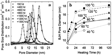 | ||
| Fig. 20 Barrett, Joyner, and Halenda (BJH) pore size distributions for fabricated mesoporous SBA-15 samples hydrothermally treated (a) at various temperatures (40 °C to 130 °C) for 24 h and (b) for different periods of time (0–120 h) at various temperatures (40 °C to 130 °C).110 Reprinted with permission from ref. 110. Copyright 2007 American Chemical Society. | ||
Mesoporous materials are typically functionalized to retain certain characteristics for desired applications. Recently, great efforts have been focused on the post-functionalization of mesoporous mixed metal oxides or calcined silica to covalently incorporate a large diversity of organic or inorganic components for catalysis, absorber and separation applications. In research done by our group, post-sulfonation treatment was applied to functionalize as-prepared mesoporous ZnO material with sulfonic groups (–SO3H), used for the esterification of FFA to produce biodiesel.111 The strategy for the post-sulfonation of the as-synthesized C@Zn core–shell solid is displayed in Fig. 21. During the sulfonation process, zinc oxide and SO3H functional groups interact electrostatically together through hydrogen bonding groups to enrich the mesopore channels. The pore size decreased significantly from 3.45 nm to 3.16 nm after post-acid treatment, proving that functional components were positioned in the internal pores of the surface. Moreover, the hydrophobicity of the functionalized catalyst was confirmed based on the absence of hydroxyl groups in the FTIR spectra in comparison with the unfunctionalized material.
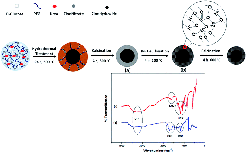 | ||
| Fig. 21 A schematic representation of the post-sulfonation of as-prepared mesoporous ZnO material to fabricate a hydrophobic heterogeneous catalyst used for ester production. FTIR spectra of mesoporous ZnO (a) and SO3H–ZnO (b) are provided for a comparative study.111 Reprinted with permission from ref. 111. Copyright 2017 Elsevier. | ||
In another research work, we hydrothermally synthesized polymeric mesoporous mixed metal oxide (ZnAl2O4) materials and then functionalized them with benzene-sulfonic acid under reflux conditions and a flow of N2.90 Furthermore, the effects of different sulfonation temperatures on the textural characteristics of the parent material were examined, as indicated in Table 3. The post-sulfonation temperature had a significant effect on the textural properties, and the surface area (399.66–189.81 m2 g−1) and porosity (3.21–2.11 nm) were reduced at high temperatures. It is worth mentioning, however, that although the pore size sharply dropped upon raising the sulfonation temperature to 200 °C, the mesostructured framework was preserved. This might be attributed to the successfully attachment of sulfonic compounds to the inner pores of the surface.
| Catalyst | SBETa | Dpb | Vpc | Acid densityd |
|---|---|---|---|---|
| a Specific surface area (m2 g−1).b Average pore diameter (nm).c Total pore volume at P/Po = 0.99 (cm3 g−1).d Based on ammonia temperature programmed desorption (NH3-TPD) measurements (mmol g−1). | ||||
| Fresh ZnAl2O4 | 396.58 | 3.45 | 0.14 | 0.19 ± 0.05 |
| SO3H-ZnAl2O4 (100 °C) | 399.66 | 3.21 | 0.15 | 1.39 ± 0.05 |
| SO3H-ZnAl2O4 (120 °C) | 352.39 | 3.10 | 0.13 | 1.95 ± 0.07 |
| SO3H-ZnAl2O4 (140 °C) | 301.65 | 2.73 | 0.10 | 2.28 ± 0.10 |
| SO3H-ZnAl2O4 (200 °C) | 189.81 | 2.11 | 0.04 | 4.17 ± 0.07 |
Fig. 22 shows a schematic illustration of the polymeric and nonpolymeric post-sulfonation treatment of an as-synthesized mesoporous ZnAl2O4 material. It reveals that post-sulfonation treatment using a polymeric approach provided more opportunities to attach acid functional groups to the surfaces of active sites. It should be noted that the diffusion of polar by-products to the surface of the catalyst causes the deactivation of the catalyst.112 Moreover, the synthesized mesoporous SO3H–ZnAl2O4 catalyst was simply recovered and recycled, which significantly reduced the cost of production.113 As a consequence, reusable eco-friendly solid acid catalysts have the potential to replace environmentally unfriendly homogeneous acid catalysts.114 The synthesized mesoporous SO3H–ZnAl2O4 catalyst was further utilized for methyl ester production, where the synthesized catalyst was able to stay highly active for eight continuous esterification reaction cycles without needing further recovery.115 The CHNS results revealed that the sulfur content leaching was insignificant from the first to the eighth cycle (dropped from 2.23 to 1.50 wt%). The remarkable stability of the synthesized mesoporous SO3H–ZnAl2O4 catalyst corresponded to the polymeric attachment of SO3H groups to the inner pore walls under proper post-sulfonation conditions.116 The same strategy was recently used to synthesize core–shell ZnO–TiO2 hollow spheres117 and a mesoporous NiO–ICG core–shell solid sphere catalyst118 via an in situ hydrothermally assisted method for ester production applications.
 | ||
| Fig. 22 A schematic illustration of the polymeric and non-polymeric post-sulfonation treatment of as-synthesized mesoporous carbon@ZnAl2O4 material.115 Reprinted with permission from ref. 115. Copyright 2016 Elsevier. | ||
The post-synthesis acid functionalization of mesoporous silica materials for catalysis applications can be carried out to maximize the activities and selectivities of these mesoporous materials via strengthening the acidity and, ultimately, the hydrophobicity. As an example, organosulfonic mesoporous silicas were synthesized and further post-functionalized with hydrophobic organic species.119 The post-synthesis acid functionalization affected the textural properties; the average pore size and total pore volume sharply declined, while the interior and exterior surface areas were highly improved. The decrease in porosity corresponded to the agglomeration of SO3H functional groups in the pore channels. Also, the thermal stability of the functionalized mesoporous catalyst increased, as no further mass loss was found after 350 °C from the thermal gravimetric analysis (TGA) plot. The catalytic performance of the synthesized catalyst was finally evaluated for the esterification of FFA, resulting in a high conversion rate of 94% at 120 °C over 120 min. In another research work,120 SO3H-OMC was fabricated via the covalent post-attachment of –SO3H-holding aryl radicals to the surface of a mesostructured material (see Fig. 23). Initially, three forms of mesoporous SBA-15 material were fabricated at three different operating temperatures (100 °C, 130 °C, and 150 °C), followed by post-sulfonation treatment in the presence of 4-benzene-diazoniumsulfonate and H3PO2 aqueous solution to modify OMC-100, OMC-130, and OMC-150 to OMC-SO3H-100, OMC-SO3H-130, and OMC-SO3H-150, respectively. The effects of the temperature-dependent post-sulfonation treatment on the textural properties and catalytic performance were studied, and the results are summarized in Table 4.120
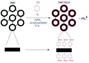 | ||
| Fig. 23 A schematic representation of the post-synthetic functionalization of mesoporous OMC with sulfonic acid reagents.120 Reprinted with permission from ref. 120. Copyright 2008 Elsevier. | ||
| Catalyst | SBETa | Pore sizeb | Pore volumec | Acid densityd | Conversione (%) |
|---|---|---|---|---|---|
| a Specific surface area (m2 g−1).b Average pore diameter (nm).c Total pore volume at P/Po = 0.99 (cm3 g−1).d Determined via a titration method.e Esterification reaction conditions: catalyst concentration, 50 mg; ethanol, 0.05 mol; oleic acid, 0.005 mol; at 80 °C for 10 h. | |||||
| OMC-100 | 1384 | 3.4 | 1.20 | — | — |
| OMC-130 | 1338 | 4.5 | 1.52 | — | — |
| OMC-150 | 1254 | 5.5 | 1.75 | — | — |
| OMC-100-SO3H | 689 | 2.1 | 0.45 | 1.95 | 69.12 |
| OMC-130-SO3H | 813 | 3.2 | 0.69 | 1.82 | 69.21 |
| OMC-150-SO3H | 741 | 4.2 | 0.85 | 1.70 | 73.59 |
Yasutaka Kuwahara et al.121 functionalized mesoporous zirconosilicate with sulfonic functional groups using direct and post-synthesis sulfonation in the presence of ammonium sulfate ((NH4)2SO4). According to the obtained results, direct-sulfonation gave a higher surface area than the other method, while samples synthesized via post-synthesis acid treatment possessed larger pore diameters and higher acid densities. This proves that the formation of larger pore diameters provides better opportunities for sulfonic functional species to successfully be incorporated into mesopore channels. Both prepared catalysts were applied to the esterification of FFA, and higher FFA conversion was achieved over the post-sulfonated mesoporous zirconosilicate catalyst in comparison with the one-pot functionalized mesoporous zirconosilicate catalyst.
Recently, considerable efforts have been devoted to employing functionalized mesoporous inorganic materials as supports for enhancing heterogeneous counterparts of homogeneous catalysts due to their well-suited textural characteristics.16 To date, a wide range of organometallic species, such as Mo, Mn, Ir, Rh, and Pd, have been incorporated into mesostructured inorganic supports.122,123 These classes of heterogenous materials not only satisfy environmental concerns regarding recovery and recyclability, but also enhance catalytic performance compared to homogenous samples. It has been reported that mesoporous MCM-41 combined with Pd components resulted in higher hydrogenation selectivity and reactivity in comparison with its homogenous counterparts due to considerable interactions between the mesoporous support and active metal species. It is worth mentioning that the existence of uniform and large diameter mesopores gives the opportunity to large species to be incorporated post-synthetically into interior mesopore sites, which can significantly enhance the dynamics, stabilities and performances of materials obtained under various reaction conditions. Generally, the main challenge is to control the incorporation of guest species into as-synthesized mesostructured materials to avoid agglomeration and the subsequent blockage of mesopore channels, which results in a loss of catalytic performance.15
These materials regularly display superior structural, physicochemical and textural properties, acidities, and catalytic performances in comparison with materials synthesized via co-condensation synthetic methods.124 Post-modification can also be performed through the deposition of consecutive layers of various metal oxides on mesostructured silica. Fig. 24(a and b) shows a schematic diagram of hydrolytic and non-hydrolytic surface sol–gel synthetic methods.125
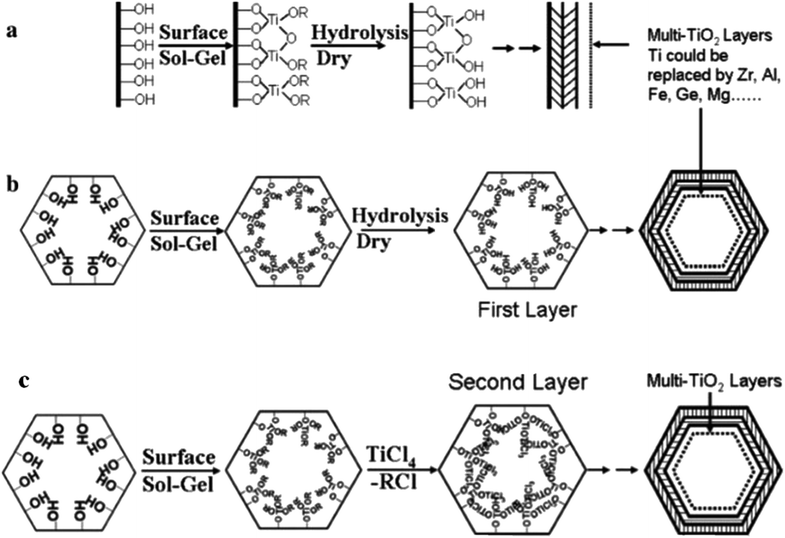 | ||
| Fig. 24 A schematic diagram showing (a and b) hydrolytic and (c) non-hydrolytic surface sol–gel synthetic methods.125 Reprinted with permission from ref. 125. Copyright 2005 American Chemical Society. | ||
Aluminosilica is a very common example of this type, where AlCl3 or Al(NO3)3 reacts with silanol species to synthesize mesoporous aluminosilica materials.126–130 In comparison with the one-pot co-condensation method, this approach provides for the better diffusion of reactants into active sites due to modified surface Lewis/Brønsted acid spots.131
As another example, Cheralathan et al.132 accomplished post-functionalization alumina distribution on the pore walls of mesoporous silica in the presence of inorganic aluminum salts using H2O/NH3 vapour as a hydrolyzing mediator at high temperature via an autoclave-assisted technique followed by calcination. In this procedure, aluminum salts were initially added into the mesopore channels of SBA-15 through a continuous multi-step wet impregnation approach; then, internal hydrolyzation took place based on H2O/NH3 vapour inside the autoclave at high temperature under autogenous pressure, homogeneously depositing aluminium hydroxide on the walls of SBA-15, which was followed by post-calcination treatment (Fig. 25). In this case, higher loadings of alumina could be incorporated on the mesopore walls of SBA-15 with insignificant pore blocking and less crystallinity.
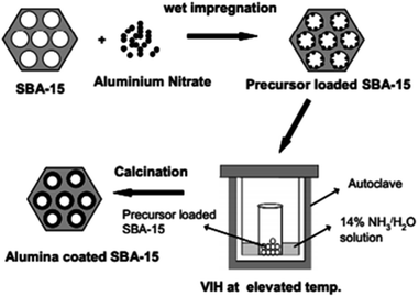 | ||
| Fig. 25 A schematic diagram of post-functionalization alumina distribution on the pore walls of mesoporous silica via the VIH method.132 Reprinted with permission from ref. 132. Copyright Elsevier. | ||
Along with transition/common metal oxides, rare-earth elements, such as Yb3+, Er3+, and Eu3+, have been repeatedly applied as functional groups that electrostatically interact with the non-cationic surface areas of mesopore frameworks.133,134
An important point that needs to be taken into consideration is that there is a higher risk of the leaching or poisoning of supported species incorporated in the mesopore channels via post-functionalizing strategies compared to those prepared via in situ approaches. In fact, supported components are generally positioned on internal mesopore surfaces where they interact with other dispersing and reacting components in the mesopore framework.
Hybrid mesoporous compounds, particularly immobilized mesoporous silica nanoparticles, involve the strong binding of organic ligands and their corresponding metal complexes to inorganic matrices. The immobilization of metal complexes can significantly enhance the surface characteristics of these mesoporous materials to maximize their interactions with biological targets.135 Eduardo Guimarães Vieira et al. immobilized two oxindolimine complexes based on zinc(II) and copper(II) which can act as carriers of water-insoluble anticancer metallodrugs.136 The immobilization of the studied complexes on the MCM-41 matrices was done as follows. Initially, solutions of the oxindolimine-copper(II) complex and the analogous zinc(II) complex were prepared at a pH value of ∼6.4. Modified and unmodified MCM-41 was added to each complex solution, and the mixtures were kept under constant stirring for 24 h at room temperature. Next, materials were filtrated and washed a number of times with a mixture of H2O/dimethyl sulfoxide and then dried at 70 °C overnight. The BET results confirmed the presence of a type IV nitrogen adsorption isotherm and H1 hysteresis loop, indicating a class of hexagonal cylinder MCM-41 (Table 5). After the immobilization of the copper(II) or zinc(II) complexes on the modified and unmodified MCM-41 matrices, the surface areas and pore volumes decreased significantly. The exception was MCM-atzac-Zn, as both its surface area and pore volume showed higher values in comparison with the MCM-atzac precursor. In fact, stronger interactions between the MCM-atzac matrix and the zinc complex 2 through an immobilization process caused the occupation of the internal pore channels and an external expansion of its distribution, resulting in an enhancement of the surface area and pore volume.
| Sample | BET surface area (m2 g−1) | Pore volume (cm3 g−1) |
|---|---|---|
| MCM-41 | 1018 | 1.225 |
| MCM-[Cu(isapn)] | 525 | 0.269 |
| MCM-[Zn(isapn)] | 641 | 0.461 |
| MCM-atzac | 716 | 0.365 |
| MCM-atzac-[Cu(isapn)] | 365 | 0.333 |
| MCM-atzac-[Zn(isapn)] | 801 | 0.382 |
The XRD diffractograms of MCM-atzac confirm the disappearance of the (110) and (200) reflections and the shifting of the (100) reflection toward higher angles in comparison with the other materials. This could be attributed to the attachment of atzac functional groups to the matrix (see Fig. 26).
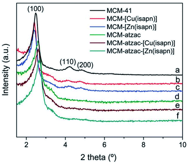 | ||
| Fig. 26 XRD diffractograms of copper(II) and zinc(II) complexes immobilized on modified and unmodified matrices.136 Reprinted with permission from ref. 136. Copyright 2019 RSC. | ||
Mesoporous silica nanoparticles have been similarly developed as nanocarriers for metal-based complexes. Mesoporous silica nanoparticles also possess remarkable characteristics as nanocarriers, including chemical stability, tunable pore size, and the ability for simple surface adaptation in the presence of various functional species for subsequent drug conjugation. In a series of experiments, mesoporous silica nanoparticles were employed as carriers for tin, titanium, and ruthenium complexes.137–139 It was reported that the entire nanostructure of the mesoporous silica–drug conjugate was associated with setting off cancer cell apoptosis, and merely a minor release of the encapsulated metallodrug created cytotoxic effects. This study was innovative, as it pointed in the direction of a non-classical strategy of action compared to those regularly perceived for these sorts of systems. Besides, it was found that the existence of the nanostructure and the minor release of metallodrug from mesoporous silica nanoparticles were the causes associated with the death of cancer cells.
For controlled release applications like drug delivery, functionalized mesostructured inorganic materials can be applied to adjust mass transfer via changing the rate of desorption of an adsorbed compound.140 In this case, the organic surface functionalization of mesostructured silica is an approach for controlling drug release via modifying the surface-binding characteristics. As an example, the release rate of ibuprofen from mesoporous silica could be significantly improved upon introducing various organic functional species to the exteriors of internal mesopores. In fact, the incorporation of organic species enhances the hydrophilic nature of the mesopore surfaces, therefore affecting ibuprofen binding strength and subsequently enhancing the desorption degree. The novel post-functionalization of mesoporous SBA-15 was proposed by Blanca González,141 where three generations (named G1, G2, and G3) of poly(propyleneimine) dendrimers with 4, 8 and 16 primary amine functional groups, respectively, at their periphery were covalently incorporated into a mesoporous framework via post-synthesis grafting (see Fig. 27(a)). The performance of these novel materials as controlled delivery devices was examined through studying the adsorption and release rates of ibuprofen (see Fig. 27(b)). The total ibuprofen loaded into these post-functionalized mesoporous SBA-15 materials gradually increased from 21.5% in pure SBA-15 to 28.8%, 40.8% and 48.0% in SBA-15-G1, SBA-15-G2, and SBA-15-G3, respectively. Ibuprofen release was fitted using the Higuchi model: [IBU] = kt1/2, where IUB represents the amount of ibuprofen released against time t, and k represents a kinetic constant. According to the proposed model, there is a linear association between the square root of time and the ibuprofen released; by gradually increasing the dendrimer generation from G1 to G3, ibuprofen release increased, confirming the excellent drug release conditions. Therefore, the adsorption and release rates of a drug can be effectively controlled via the selection of a proper dendrimer group for modifying mesoporous silica. In a comparative study, amine functionalized mesoporous silica gave slower rates of ibuprofen release, which was consistent with the less hydrophilic nature of its surface.142
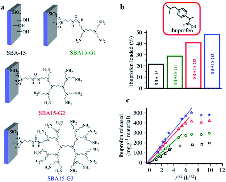 | ||
| Fig. 27 (a) A schematic representation of pure SBA-15 and post-functionalized SBA-15-G1, SBA-15-G2, and SBA-15-G3, using poly(propyleneimine) dendrimers. (b) Ibuprofen loading percentages and (c) ibuprofen released against time by pure SBA-15 and post-functionalized SBA-15-G1, SBA-15-G2, and SBA-15-G3; squares: pure SBA-15; stars: SBA15-G1; circles: SBA15-G2; triangles: SBA15-G3;141 modified from ref. 140. Reprinted with permission from ref. 140 and 141. Copyright 2009 and 2012 respectively RSC. | ||
Amorphous silica materials have the potential to be applied to controlled release procedures due to their advantageous characteristics, including their isolated, uniform and large diameter pore voids, which can host guest components. In this case, each isolated pore void could be a nanoscale host for foreign molecules. An alternate technique to control release rates is to control the mass transfer of guest molecules from the components that act as molecular gates to the interior/exterior of the mesostructured matrix.143 An intermolecular reversible photodimerization–cleavage cycle is reported as a promising post-synthetic modification approach to regulate access to mesopore channels. Irradiation from 250 nm UV light causes the cleavage of the coumarin dimer, regenerating its monomer. Subsequently, the “double doors” of mesoporous silica will be broken, resulting in the release of foreign components. However, irradiation from UV light with a wavelength higher than 310 nm is insufficient to open the “double doors” of the mesopore channels, resulting in the trapping of guest particles inside the pores. The “open/closed double doors” methodology is highly promising for the photo-switchable controlled release of various species.144 The modified pore voids are expected to provide more effective control of the passage of guest molecules through molecular gates than unmodified ones.
Through a post-synthesis oxidation approach, introduced thiol groups can be oxidized via a post-synthetic method. However, the main drawback to this post-synthesis oxidation method is that the good preservation of the mesopore structure cannot be guaranteed. Through in situ oxidation, the oxidation of thiol functional groups is concurrent with the formation of the mesostructured material. This is the best approach to counter the collapse of the mesopore walls due to the post-synthesis oxidation approach.145–149 Mesoporous catalysts synthesized via in situ oxidation possess remarkable characteristics, such as high surface areas, uniform and large pores, and good mechanical and thermal stabilities, making them favourable for various catalytic applications.150–156
Summary and outlook
The main key to the wide-ranging potential applications of mesoporous inorganic materials is the ability for their interior pore channels and surface areas to be modified using numerous organic/inorganic components. Up to now, numerous synthetic schemes have been proposed to attain better control through the incorporation and distribution of functional components within the mesostructured matrix. Through the cautious selection of components and reaction conditions, functional species could be selectively diffused on the internal surfaces of mesopore channels or within the mesopore wall frameworks. The availability of a large number of functionalization options presents an increased opportunity to design and synthesize these materials, continuing with the suitable modification of the structural, textural, and physicochemical properties of these materials, particularly at the molecular level. The use of both organic and inorganic functional components, such as common or transition metal oxides, rare-earth elements, and acid/base agents, to functionalize mesoporous inorganic materials has been increasingly exercised through either in situ (co-assembly/co-condensation) or post-synthetic functionalization strategies based on a variety of physicochemical interactions.Generally, broadening the range of characteristics of mesoporous materials to expand their range of possible applications greatly requires expanding and diversifying the composition of mesoporous materials. It is essential to adjust the interfacial characteristics via surface functionalization procedures in order to develop their functionalities. Moreover, the hierarchical frameworks and porosities, in particular pore geometry, pore size, pore volume, and wall thickness, which are related to the performances of mesoporous materials, should be well established, and interfacial shortcomings require additional research. On the other hand, studies should also focus on multi-component and multi-layered mesopore structures, obtained via multiple templates, which could lead to unpredicted effects that are likely to allow multi-functional materials to be exploited for various applications. To sum up, the preparation and functionalization of mesoporous materials should move in the following corresponding directions: (i) the development of nanotechnology should cover more varieties of precursors for templated mesostructures; (ii) comparative analyses of the interactions between templating components and precursors under various synthesis conditions should be carried out; and (iii) the exploration of expendable and eco-friendly templates for synthesizing mesoporous materials with more industrial value should be conducted. Although some topics have already been well developed, much remains to be explored and discovered.
Abbreviation
| NH3-TPD | Ammonia temperature programmed desorption |
| ERS-8 | Amorphous microporous silica-alumina |
| BJH | Barrett, Joyner and Halenda |
| BET | Brunauer–Emmett–Teller |
| DLCT | Direct liquid crystal templating |
| DBSA | Dodecylbenzenesulfonic acid |
| EISA | Evaporation induced self-assembly |
| FTIR | Fourier-transform infrared spectroscopy |
| FFA | Free fatty acid |
| M41S | Group name of mesoporous MCM materials |
| HMS | Hexagonal mesoporous silica |
| HRTEM | High resolution transmission electron microscopy |
| MSA | Mesoporous silica alumina |
| MCF | Mesostructured cellular foam |
| MSN | Mesostructured silica nanoparticle |
| MSU | Michigan State University |
| MCM | Mobil Composition of Matter |
| MDD | Molecular designed dispersion |
| NC | Nanocrystal |
| OMS | Ordered mesoporous silica |
| PMO | Periodic mesoporous organosilica |
| PHTS | Plugged hexagonal templated silica |
| PEG | Polyethylene glycol |
| PEO | Polyethylene oxide |
| PPO | Polypropylene oxide |
| SBA | Santa Barbara Amorphous |
| SEM | Scanning electron microscopy |
| SBET | Specific surface area based on BET |
| TMO | Templated mesostructured transition metal oxide |
| TEOS | Tetraethylorthosilicate |
| TPP | Tetraphenylporphyrin |
| TGA | Thermal gravimetric analysis |
| TEM | Transmission electron microscopy |
| XRD | X-ray diffraction |
Conflicts of interest
There are no conflicts to declare.Acknowledgements
The authors would like to extend their profound gratitude to the Universiti Putra Malaysia (UPM) for financial support that funded this research work through Geran Putra UPM GP-IPB/2016/9515200. We also would like to convey our deepest gratitude and appreciation to Dr Maryam Shad for her ceaseless support.References
- K. Szczodrowski, B. Prélot, S. Lantenois, J. Zajac, M. Lindheimer, D. Jones, A. Julbe and A. van der Lee, Microporous Mesoporous Mater., 2008, 110, 111–118 CrossRef CAS.
- E. B. Celer and M. Jaroniec, J. Am. Chem. Soc., 2006, 128, 14408–14414 CrossRef CAS PubMed.
- N. D. Petkovich and A. Stein, Chem. Soc. Rev., 2013, 42, 3721–3739 RSC.
- N. Pal and A. Bhaumik, Adv. Colloid Interface Sci., 2013, 189–190, 21–41 CrossRef CAS PubMed.
- R. Hosseinzadeh, K. Khorsandi and S. Hemmaty, PLoS One, 2013, 8, e57353 CrossRef CAS PubMed.
- T. Wagner, S. Haffer, C. Weinberger, D. Klaus and M. Tiemann, Chem. Soc. Rev., 2013, 42, 4036–4053 RSC.
- W. Li and D. Zhao, Chem. Commun., 2013, 49, 943–946 RSC.
- A. J. Schwanke, R. Balzer and S. Pergher, in Micro and Nano Technologies, ed. C. B. T.-H. of N. for I. A. Mustansar Hussain, Elsevier, 2018, pp. 908–915 Search PubMed.
- P. Hesemann, T. P. Nguyen and S. El Hankari, Materials, 2014, 7, 2978–3001 CrossRef PubMed.
- V. Meynen, P. Cool and E. F. Vansant, Microporous Mesoporous Mater., 2009, 125, 170–223 CrossRef CAS.
- S. Soltani, U. Rashid, S. I. Al-Resayes and I. A. Nehdi, Energy Convers. Manag., 2017, 141, 183–205 CrossRef CAS.
- T.-Y. Ma, L. Liu and Z.-Y. Yuan, Chem. Soc. Rev., 2013, 42, 3977–4003 RSC.
- S. S. Park, M. Santha Moorthy and C.-S. Ha, Npg Asia Mater, 2014, 6, e96 CrossRef CAS.
- C. Perego and R. Millini, Chem. Soc. Rev., 2013, 42, 3956–3976 RSC.
- Q. Huo, Synthetic Chemistry of the Inorganic Ordered Porous Materials, Elsevier, Amsterdam, 2011, ch. 16, pp. 339–373 Search PubMed.
- W. Xin and Y. Song, RSC Adv., 2015, 5, 83239–83285 RSC.
- C. T. Kresge and W. J. Roth, Chem. Soc. Rev., 2013, 42, 3663–3670 RSC.
- Y. Wan and D. Zhao, Chem. Rev., 2007, 107, 2821–2860 CrossRef CAS PubMed.
- B. A. Holmberg, H. Wang and Y. Yan, Microporous Mesoporous Mater., 2004, 74, 189–198 CrossRef CAS.
- G. Crépeau, V. Montouillout, A. Vimont, L. Mariey, T. Cseri and F. Maugé, J. Phys. Chem. B, 2006, 110, 15172–15185 CrossRef PubMed.
- C. Perego, S. Amarilli, A. Carati, C. Flego, G. Pazzuconi, C. Rizzo and G. Bellussi, Microporous Mesoporous Mater., 1999, 27, 345–354 CrossRef CAS.
- L. Zhang, J. Yan, M. Zhou, Y. Yang and Y.-N. Liu, Appl. Surf. Sci., 2013, 268, 237–245 CrossRef CAS.
- L. Zhang, J. Yan, M. Zhou, Y. Yu, Y. Liu and Y. Liu, Trans. Nonferrous Met. Soc. China, 2014, 24, 743–749 CrossRef CAS.
- S. K. Mehta and G. Kaur, Microemulsions: Thermodynamic and Dynamic Properties, 2011, pp. 381–406 Search PubMed.
- D. Lombardo, P. Calandra, D. Barreca, S. Magazù and M. A. Kiselev, Nanomaterials, 2016, 6, 125–151 CrossRef PubMed.
- J. Silvestre-Albero, A. Sepúlveda-Escribano and F. R. Reinoso, Microporous Mesoporous Mater., 2008, 113, 362–369 CrossRef CAS.
- A. C. Pradhan, A. Paul and G. R. Rao, J. Chem. Sci., 2017, 129, 381–395 CrossRef CAS.
- D. M. Bezerra, I. W. Zapelini, K. N. Franke, M. E. Ribeiro and D. Cardoso, Mater. Charact., 2019, 154, 103–115 CrossRef CAS.
- F. Carniato, C. Bisio, G. Paul, G. Gatti, L. Bertinetti, S. Coluccia and L. Marchese, J. Mater. Chem., 2010, 20, 5504–5509 RSC.
- D. Rath, S. Rana and K. M. Parida, RSC Adv., 2014, 4, 57111–57124 RSC.
- A. J. Schwanke, R. Balzer and S. Pergher, Handbook of Ecomaterials, ed. L. M. T. Martínez, O. V. Kharissova and B. I. Kharisov, Springer International Publishing, Cham, 2017, pp. 1–22 Search PubMed.
- C. Gérardin, J. Reboul, M. Bonne and B. Lebeau, Chem. Soc. Rev., 2013, 42, 4217–4255 RSC.
- K. Wang, Y. Lin, M. A. Morris and J. D. Holmes, J. Mater. Chem., 2006, 16, 4051–4057 RSC.
- C. R. P. Silva, F. da Rocha Ferreira, G. D. Webler, A. O. S. da Silva, F. C. de Abreu and E. J. S. Fonseca, Mater. Res. Express, 2017, 4, 65402 CrossRef.
- S. Iqbal and J. Il Yun, RSC Adv., 2018, 8, 32211–32220 RSC.
- R. Narayan, U. Y. Nayak, A. M. Raichur and S. Garg, Pharmaceutics, 2018, 10, 118 CrossRef CAS PubMed.
- V. Tkachenko, C. Matei Ghimbeu, C. Vaulot, L. Josien, L. Vidal, J. Poly and A. Chemtob, Langmuir, 2019, 35, 16324–16334 CrossRef CAS PubMed.
- L. Gai, Z. Chen, H. Jiang, Y. Tian, Q. Wang and D. Cui, J. Cryst. Growth, 2006, 291, 527–532 CrossRef CAS.
- D. Gao, A. Duan, X. Zhang, K. Chi, Z. Zhao, J. Li, Y. Qin, X. Wang and C. Xu, J. Mater. Chem. A, 2015, 3, 16501–16512 RSC.
- J. Herzberger, K. Niederer, H. Pohlit, J. Seiwert, M. Worm, F. R. Wurm and H. Frey, Chem. Rev., 2016, 116, 2170–2243 CrossRef CAS PubMed.
- R. M. Grudzien, B. E. Grabicka and M. Jaroniec, Appl. Surf. Sci., 2007, 253, 5660–5665 CrossRef CAS.
- P. F. Fulvio, B. E. Grabicka, R. M. Grudzien and M. Jaroniec, Adsorpt. Sci. Technol., 2007, 25, 439–449 CrossRef CAS.
- E. B. Celer, M. Kruk, Y. Zuzek and M. Jaroniec, J. Mater. Chem., 2006, 16, 2824–2833 RSC.
- C.-L. Lin, Y.-S. Pang, M.-C. Chao, B.-C. Chen, H.-P. Lin, C.-Y. Tang and C.-Y. Lin, J. Phys. Chem. Solids, 2008, 69, 415–419 CrossRef CAS.
- L. B. de O. Freitas, I. J. G. Bravo, W. A. de A. Macedo and E. M. B. de Sousa, J. Sol-Gel Sci. Technol., 2016, 77, 186–204 CrossRef CAS.
- B.-H. Min, E.-Y. Jeong, M. Thommes and S.-E. Park, Chem. Commun., 2011, 47, 4673–4675 RSC.
- C. Herdes, M. A. Santos, S. Abelló, F. Medina and L. F. Vega, Appl. Surf. Sci., 2005, 252, 538–547 CrossRef CAS.
- P. Van Der Voort, P. I. Ravikovitch, K. P. De Jong, A. V Neimark, A. H. Janssen, M. Benjelloun, E. Van Bavel, P. Cool, B. M. Weckhuysen and E. F. Vansant, Chem. Commun., 2002, 9, 1010–1011 RSC.
- S. Meoto, N. Kent, M. M. Nigra and M.-O. Coppens, Microporous Mesoporous Mater., 2017, 249, 61–66 CrossRef CAS.
- Y. Mao, Y. Zhou, H. Wen, J. Xie, W. Zhang and J. Wang, New J. Chem., 2014, 38, 3295–3301 RSC.
- L. Hermida, J. Agustian, A. Z. Abdullah and A. R. Mohamed, Open Chem., 2019, 17, 1000–1016 Search PubMed.
- K. De Witte, V. Meynen, M. Mertens, O. I. Lebedev, G. Van Tendeloo, A. Sepúlveda-Escribano, F. Rodríguez-Reinoso, E. F. Vansant and P. Cool, Appl. Catal., B, 2008, 84, 125–132 CrossRef CAS.
- J. Liu, C. Li, Q. Yang, J. Yang and C. Li, Langmuir, 2007, 23, 7255–7262 CrossRef CAS PubMed.
- S.-Y. Chen and S. Cheng, Chem. Mater., 2007, 19, 3041–3051 CrossRef CAS.
- R. Gao, W.-L. Dai, X. Yang, H. Li and K. Fan, Appl. Catal., A, 2007, 332, 138–145 CrossRef CAS.
- P. Schmidt-Winkel, W. Lukens Wayne, P. Yang, D. I. Margolese, J. S. Lettow, J. Y. Ying and G. D. Stucky, Chem. Mater., 2000, 12, 686–696 CrossRef CAS.
- X. Ma, H. Sun and P. Yu, J. Mater. Sci., 2008, 43, 887–891 CrossRef CAS.
- H. Zhong, G. Zhu, P. Wang, J. Liu, J. Yang and Q. Yang, J. Chromatogr. A, 2008, 1190, 232–240 CrossRef CAS PubMed.
- J. Allouche, J.-C. Dupin and D. Gonbeau, Chem. Commun., 2011, 47, 7476–7478 RSC.
- S. A. Bagshaw and I. J. Bruce, Microporous Mesoporous Mater., 2008, 109, 199–209 CrossRef CAS.
- Z. Jin, X. Wang and X. Cui, J. Non-Cryst. Solids, 2007, 353, 2507–2514 CrossRef CAS.
- K. Biswas, J. C. Ray, J.-S. Choi and W.-S. Ahn, J. Non-Cryst. Solids, 2008, 354, 1–9 CrossRef CAS.
- L. Zhang, L. Jin, B. Liu and J. He, Front. Chem., 2019, 7, 22 CrossRef CAS PubMed.
- M. A. A. Aziz, A. A. Jalil, S. Triwahyono, R. R. Mukti, Y. H. Taufiq-Yap and M. R. Sazegar, Appl. Catal., B, 2014, 147, 359–368 CrossRef CAS.
- M. Davidson, Y. Ji, G. J. Leong, N. C. Kovach, B. G. Trewyn and R. M. Richards, ACS Appl. Nano Mater., 2018, 1, 4386–4400 CrossRef CAS.
- D. Xu, H. Lv and B. Liu, Front. Chem., 2018, 6, 550 CrossRef CAS PubMed.
- K. An and G. A. Somorjai, Catal. Lett., 2015, 145, 233–248 CrossRef CAS.
- M. Shamzhy, M. Opanasenko, P. Concepción and A. Martínez, Chem. Soc. Rev., 2019, 48, 1095–1149 RSC.
- S. C. Warren, L. C. Messina, L. S. Slaughter, M. Kamperman, Q. Zhou, S. M. Gruner, F. J. DiSalvo and U. Wiesner, Science, 2008, 320, 1748–1752 CrossRef CAS PubMed.
- N. Kosinov, C. Liu, E. J. M. Hensen and E. A. Pidko, Chem. Mater., 2018, 30, 3177–3198 CrossRef CAS PubMed.
- D. P. Sahoo, D. Rath, B. Nanda and K. M. Parida, RSC Adv., 2015, 5, 83707–83724 RSC.
- Q. Tian, Z. Zhang, L. Yang and S. Hirano, Electrochim. Acta, 2014, 138, 155–162 CrossRef CAS.
- J. Du, X. Lai, N. Yang, J. Zhai, D. Kisailus, F. Su, D. Wang and L. Jiang, ACS Nano, 2011, 5, 590–596 CrossRef CAS PubMed.
- L. Chen, B. Yao, Y. Cao and K. Fan, J. Phys. Chem. C, 2007, 111, 11849–11853 CrossRef CAS.
- M. A. Abdolahi Sadatlu and N. Mozaffari, Sol. Energy, 2016, 133, 24–34 CrossRef CAS.
- L. Mahoney and R. T. Koodali, Materials, 2014, 7, 2697–2746 CrossRef PubMed.
- K. Na and G. A. Somorjai, Catal. Lett., 2015, 145, 193–213 CrossRef CAS.
- B. Niu, X. Wang, K. Wu, X. He and R. Zhang, Materials, 2018, 11, 1910 CrossRef PubMed.
- J. L. Vivero-Escoto, Y.-D. Chiang, K. Wu and Y. Yamauchi, Sci. Technol. Adv. Mater., 2012, 13, 13003 CrossRef PubMed.
- J. H. Pan, X. S. Zhao and W. I. Lee, Chem. Eng. J., 2011, 170, 363–380 CrossRef CAS.
- S. Ribbens, V. Meynen, G. Van Tendeloo, X. Ke, M. Mertens, B. U. W. Maes, P. Cool and E. F. Vansant, Microporous Mesoporous Mater., 2008, 114, 401–409 CrossRef CAS.
- D. Fattakhova-Rohlfing, A. Zaleska and T. Bein, Chem. Rev., 2014, 114, 9487–9558 CrossRef CAS PubMed.
- C.-C. Tsai and H. Teng, Chem. Mater., 2006, 18, 367–373 CrossRef CAS.
- M. Shahrezaei, S. Habibzadeh, A. A. Babaluo, H. Hosseinkhani, M. Haghighi, A. Hasanzadeh and R. Tahmasebpour, J. Exp. Nanosci., 2017, 12, 45–61 CrossRef CAS.
- S. Sun, W. Wang, M. Shang, J. Ren and L. Zhang, J. Mol. Catal. A: Chem., 2010, 320, 72–78 CrossRef CAS.
- Z. Wu, Q. Li, D. Feng, P. A. Webley and D. Zhao, J. Am. Chem. Soc., 2010, 132, 12042–12050 CrossRef CAS PubMed.
- H. Ji, X. Liu, X. Wang and X. Yao, J. Colloid Interface Sci., 2011, 353, 356–362 CrossRef CAS PubMed.
- S. Soltani, U. Rashid, R. Yunus, Y. H. Taufiq-Yap and S. I. Al-Resayes, Renewable Energy, 2016, 99, 1235–1243 CrossRef CAS.
- S. Soltani, U. Rashid, I. A. Nehdi and S. I. Al-Resayes, Chem. Eng. Technol., 2017, 40, 1931–1939 CrossRef CAS.
- S. Soltani, U. Rashid, R. Yunus and Y. H. Taufiq-Yap, Fuel, 2016, 178, 253–262 CrossRef CAS.
- G. L. Athens, R. M. Shayib and B. F. Chmelka, Curr. Opin. Colloid Interface Sci., 2009, 14, 281–292 CrossRef CAS.
- S. Fujita and S. Inagaki, Chem. Mater., 2008, 20, 891–908 CrossRef CAS.
- N. Mizoshita, T. Tani and S. Inagaki, Chem. Soc. Rev., 2011, 40, 789–800 RSC.
- Q. Yang, J. Liu, L. Zhang and C. Li, J. Mater. Chem., 2009, 19, 1945–1955 RSC.
- S. Inagaki, S. Guan, T. Ohsuna and O. Terasaki, Nature, 2002, 416, 304–307 CrossRef CAS PubMed.
- G. Morales, G. Athens, B. F. Chmelka, R. van Grieken and J. A. Melero, J. Catal., 2008, 254, 205–217 CrossRef CAS.
- Y. Chen, Y. Cao, Y. Suo, G.-P. Zheng, X.-X. Guan and X.-C. Zheng, J. Taiwan Inst. Chem. Eng., 2015, 51, 186–192 CrossRef CAS.
- L. Zhao, H. Qin, R. Wu and H. Zou, J. Chromatogr. A, 2012, 1228, 193–204 CrossRef CAS PubMed.
- F. Mumtaz, M. Zuber, K. M. Zia, T. Jamil and R. Hussain, Korean J. Chem. Eng., 2013, 30, 2259–2263 CrossRef CAS.
- A. Drelinkiewicz, Z. Kalemba-Jaje, E. Lalik and R. Kosydar, Fuel, 2014, 116, 760–771 CrossRef CAS.
- Q. Yang, J. Liu, J. Yang, M. P. Kapoor, S. Inagaki and C. Li, J. Catal., 2004, 228, 265–272 CrossRef CAS.
- Q. Yang, M. P. Kapoor, S. Inagaki, N. Shirokura, J. N. Kondo and K. Domen, J. Mol. Catal. A: Chem., 2005, 230, 85–89 CrossRef CAS.
- R. Liu, Y. Shi, Y. Wan, Y. Meng, F. Zhang, D. Gu, Z. Chen, B. Tu and D. Zhao, J. Am. Chem. Soc., 2006, 128, 11652–11662 CrossRef CAS PubMed.
- S. Neyshtadt, M. Kalina and G. L. Frey, Adv. Mater., 2008, 20, 2541–2546 CrossRef CAS.
- S. Kirmayer, E. Dovgolevsky, M. Kalina, E. Lakin, S. Cadars, J. D. Epping, A. Fernández-Arteaga, C. Rodríguez-Abreu, B. F. Chmelka and G. L. Frey, Chem. Mater., 2008, 20, 3745–3756 CrossRef CAS.
- E. Dovgolevsky, S. Kirmayer, E. Lakin, Y. Yang, C. J. Brinker and G. L. Frey, J. Mater. Chem., 2008, 18, 423–436 RSC.
- H. Fan, K. Yang, D. M. Boye, T. Sigmon, K. J. Malloy, H. Xu, G. P. López and C. J. Brinker, Science, 2004, 304, 567–571 CrossRef CAS PubMed.
- G. Wu, J. Li, Z. Fang, L. Lan, R. Wang, T. Lin, M. Gong and Y. Chen, Chem. Eng. J., 2015, 271, 1–13 CrossRef CAS.
- Z. Wu, P. A. Webley and D. Zhao, J. Mater. Chem., 2012, 22, 11379–11389 RSC.
- M. Kruk and L. Cao, Langmuir, 2007, 23, 7247–7254 CrossRef CAS PubMed.
- S. Soltani, U. Rashid, S. I. Al-Resayes and I. A. Nehdi, J. Cleaner Prod., 2017, 144, 482–491 CrossRef CAS.
- V. B. Veljkovic, S. H. Lakicevic, O. S. Stamenkovic, Z. B. Todorovic and M. L. Lazic, Fuel, 2006, 2671–2675 CrossRef CAS.
- F. Guo, Z. Fang, C. C. Xu and R. L. Smith, Prog. Energy Combust. Sci., 2012, 38, 672–690 CrossRef CAS.
- J. H. Clark and D. J. Macquarrie, Chem. Commun., 1998, 8, 853–860 RSC.
- S. Soltani, U. Rashid, I. Arbi and S. I. Al-resayes, J. Taiwan Inst. Chem. Eng., 2016, 1–10 Search PubMed.
- U. Rashid, S. Soltani, S. I. Al-Resayes and I. A. Nehdi, in Metal Oxides, Elsevier, 2018. pp. 303–319 Search PubMed.
- S. Soltani, N. Khanian, U. Rashid and T. S. Y. Choong, Renewable Energy, 2020, 151, 1076–1081 CrossRef.
- S. Soltani, N. Khanian, U. Rashid and T. S. Yaw Choong, RSC Adv., 2019, 9, 31306–31315 RSC.
- I. Mbaraka and B. Shanks, J. Catal., 2005, 229, 365–373 CrossRef CAS.
- R. Liu, X. Wang, X. Zhao and P. Feng, Carbon, 2008, 46, 1664–1669 CrossRef CAS.
- Y. Kuwahara, T. Fujitani and H. Yamashita, Catal. Today, 2014, 237, 18–28 CrossRef CAS.
- P. Das, A. R. Silva, A. P. Carvalho, J. Pires and C. Freire, J. Mater. Sci., 2009, 44, 2865–2875 CrossRef CAS.
- Z. Huang, M. Brookhart, A. S. Goldman, S. Kundu, A. Ray, S. L. Scott and B. C. Vicente, Adv. Synth. Catal., 2009, 351, 188–206 CrossRef CAS.
- Y. Wang, K.-Y. Lee, S. Choi, J. Liu, L.-Q. Wang and C. H. F. Peden, Green Chem., 2007, 9, 540–544 RSC.
- W. Yan, S. M. Mahurin, S. H. Overbury and S. Dai, Chem. Mater., 2005, 17, 1923–1925 CrossRef CAS.
- D. U. Tulyaganov, A. A. Reddy, V. V Kharton and J. M. F. Ferreira, J. Power Sources, 2013, 242, 486–502 CrossRef CAS.
- M. R. Agliullin, V. P. Talzi, N. A. Filippova, V. R. Bikbaeva, S. V Bubennov, T. R. Prosochkina, N. G. Grigorieva, N. Narender and B. I. Kutepov, Appl. Petrochem. Res., 2018, 8, 141–151 CrossRef CAS.
- P. Sreenivasulu, N. Viswanadham and S. K. Saxena, J. Mater. Chem. A, 2014, 2, 7354–7359 RSC.
- N. Musselwhite, K. Na, K. Sabyrov, S. Alayoglu and G. A. Somorjai, J. Am. Chem. Soc., 2015, 137, 10231–10237 CrossRef CAS PubMed.
- J. Čejka and S. Mintova, Catal. Rev., 2007, 49, 457–509 CrossRef.
- D. Srinivas and P. Ratnasamy, Microporous Mesoporous Mater., 2007, 105, 170–180 CrossRef CAS.
- K. K. Cheralathan, T. Hayashi and M. Ogura, Microporous Mesoporous Mater., 2008, 116, 406–415 CrossRef CAS.
- B. An, S. S. Park, Y. Jung, I. Kim and C.-S. Ha, Mol. Cryst. Liq. Cryst., 2008, 492, 210/[574]–220/[584] Search PubMed.
- E. Besson, A. Mehdi, C. Reyé and R. J. P. Corriu, J. Mater. Chem., 2006, 16, 246–248 RSC.
- W. A. Wani, S. Prashar, S. Shreaz and S. Gómez-Ruiz, Coord. Chem. Rev., 2016, 312, 67–98 CrossRef CAS.
- E. Guimarães Vieira, R. B. Miguel, D. Rodrigues da Silva, R. Boni Fazzi, R. A. A. de Couto, J. H. Marin, M. L. A. Temperini, J. da Silva Shinohara, H. E. Toma, L. C. Russo, Y. T. Magalhães, N. L. Dias Filho, F. L. Forti and A. M. da Costa Ferreira, New J. Chem., 2019, 43, 386–398 RSC.
- D. Díaz-García, D. Cenariu, Y. Pérez, P. Cruz, I. del Hierro, S. Prashar, E. Fischer-Fodor and S. Gómez-Ruiz, Dalton Trans., 2018, 47, 12284–12299 RSC.
- Y. Ellahioui, M. Patra, C. Mari, R. Kaabi, J. Karges, G. Gasser and S. Gómez-Ruiz, Dalton Trans., 2019, 48, 5940–5951 RSC.
- S. Gómez-Ruiz, A. García-Peñas, S. Prashar, A. Rodríguez-Diéguez and E. Fischer-Fodor, Materials, 2018, 11, 224 CrossRef PubMed.
- V.-R. María, I.-B. Isabel and C. Montserrat, Philos. Trans. R. Soc., A, 2012, 370, 1400–1421 CrossRef PubMed.
- B. González, M. Colilla, C. L. de Laorden and M. Vallet-Regí, J. Mater. Chem., 2009, 19, 9012–9024 RSC.
- Q. Tang, Y. Xu, D. Wu, Y. Sun, J. Wang, J. Xu and F. Deng, J. Controlled Release, 2006, 114, 41–46 CrossRef CAS PubMed.
- J. Kärger, T. Binder, C. Chmelik, F. Hibbe, H. Krautscheid, R. Krishna and J. Weitkamp, Nat. Mater., 2014, 13, 333–343 CrossRef PubMed.
- C. L. Birmingham, V. Canadien, N. A. Kaniuk, B. E. Steinberg, D. E. Higgins and J. H. Brumell, Nature, 2008, 451, 350 CrossRef CAS PubMed.
- D. Feng, T.-N. Gao, M. Fan, A. Li, K. Li, T. Wang, Q. Huo and Z.-A. Qiao, NPG Asia Mater., 2018, 10, 800–809 CrossRef CAS.
- X. Deng, K. Chen and H. Tüysüz, Chem. Mater., 2017, 29, 40–52 CrossRef CAS.
- E. Zhang, M. E. Casco, F. Xu, W.-B. Sheng, S. Oswald, L. Giebeler, K. Wegner, L. Borchardt and S. Kaskel, Carbon, 2019, 149, 743–749 CrossRef CAS.
- J. Hövelmann, T. M. Stawski, R. Besselink, H. M. Freeman, K. M. Dietmann, S. Mayanna, B. R. Pauw and L. G. Benning, Nanoscale, 2019, 11, 6939–6951 RSC.
- Y. Shi, Y. Wan and D. Zhao, Chem. Soc. Rev., 2011, 40, 3854–3878 RSC.
- J. Deng, L. Zhang, H. Dai and C.-T. Au, Appl. Catal., A, 2009, 352, 43–49 CrossRef CAS.
- H. Jiang, T. Zhao, C. Li and J. Ma, Chem. Commun., 2011, 47, 8590–8592 RSC.
- S. H. Gage, J. Engelhardt, M. J. Menart, C. Ngo, G. J. Leong, Y. Ji, B. G. Trewyn, S. Pylypenko and R. M. Richards, ACS Omega, 2018, 3, 7681–7691 CrossRef CAS PubMed.
- H. Zhu, Y. Chen, Z. Wang, W. Liu and L. Wang, RSC Adv., 2018, 8, 14888–14897 RSC.
- N. Pal and A. Bhaumik, RSC Adv., 2015, 5, 24363–24391 RSC.
- X. Wang, Y. Liu, T. Zhang, Y. Luo, Z. Lan, K. Zhang, J. Zuo, L. Jiang and R. Wang, ACS Catal., 2017, 7, 1626–1636 CrossRef CAS.
- X. Kang, K. Lyu, L. Li, J. Li, L. Kimberley, B. Wang, L. Liu, Y. Cheng, M. D. Frogley, S. Rudić, A. J. Ramirez-Cuesta, R. A. W. Dryfe, B. Han, S. Yang and M. Schröder, Nat. Commun., 2019, 10, 4466 CrossRef PubMed.
| This journal is © The Royal Society of Chemistry 2020 |

