DOI:
10.1039/D0RA00192A
(Paper)
RSC Adv., 2020,
10, 12475-12484
Molecular simulations of gas transport in hydrogenated nitrile butadiene rubber and ethylene–propylene–diene rubber†
Received
8th January 2020
, Accepted 16th March 2020
First published on 27th March 2020
Abstract
Diffusion and sorption of five gases (H2, N2, O2, CO2, CH4) in hydrogenated nitrile butadiene rubber (HNBR) and ethylene–propylene–diene rubber (EPDM) have been investigated by molecular dynamics (MD) and grand canonical Monte Carlo (GCMC) simulations. The diffusion coefficients of gas molecules in HNBR and EPDM are well correlated with the effective penetrant diameter except for CO2. CO2 shows a lower diffusion coefficient due to its linear shape. Additionally, the favorable interaction between CO2 and HNBR is another factor for its lower diffusion coefficient in HNBR. HNBR shows lower diffusion coefficients than EPDM. This is because the polar –CN groups in HNBR chains increase interchain cohesion and result in tight intermolecular packing, low free volume and poor chain mobility, which decreases the diffusion coefficients of HNBR. The solubility coefficients of CH4, O2, N2 and H2 in HNBR are lower than those in EPDM, which is a result of the weak HNBR–penetrant interactions and low free volume of HNBR. However, the solubility coefficient of CO2 in HNBR is higher than in EPDM. This is attributed to the strong interaction between CO2 and HNBR. H2, O2, N2 and CH4 show lower permeability coefficients in HNBR than in EPDM, while CO2 has higher permeability coefficients in HNBR. These molecular details provide critical information for the understanding of structures and gas transport between HNBR and EPDM.
1. Introduction
Due to the excellent elasticity and resilience, elastomer seals have widespread use as sealing components, such as hoses, gaskets, O-rings, and so forth, in the gas and oil industry.1 Ethylene–propylene–diene (EPDM) rubber and hydrogenated nitrile butadiene rubber (HNBR) are two of the most common elastomer materials used in the sealing industry. EPDM elastomer has become a barrier sealing material of significant commercial importance due to its superior resistance to thermal, oxidative, and radiation degradation coupled with its ability to accommodate high volume fractions of filler and liquid plasticizer.2,3 HNBR is prepared by saturated the carbon–carbon double bonds in the backbone of nitrile butadiene rubber (NBR) with hydrogen, which is widely used for applications in the oil and gas industry due to its oil resistance, heat aging and low-temperature flexibility.4,5
As sealing components, one of their key roles is to protect sensitive monitoring equipment from contamination by gases and fluids. The permeation of certain gases through the seals will lead to corrosion of the electronic components that are intended to be protected. Hence, the study of gas permeation behavior of elastomer materials plays an important role in the design of high performance sealing materials, the prediction of the internal atmosphere of the sealed devices and the assessment of the device life. Experimental and computational researches on diffusion and sorption of small molecules in polymeric materials are essential due to the important applications of polymeric materials as barriers or membranes. In order to understand the mechanisms of gas transport in the various polymers of interest, it is useful to relate the chemical composition of the polymer and its morphology to the sorption isotherms and diffusivities of penetrants within it. In this respect, molecular simulations have significant benefits in understanding the sorption and diffusion phenomena in polymers at the molecular scale.
Molecular dynamics (MD) simulations have been extensively used in order to investigate the permeation of gas molecules in glassy and rubbery polymers.6,7 The studied rubbery polymers include silicon rubber,8,9 styrene–butadiene rubber (SBR),10,11 polyisobutylene,12,13 natural rubber,14 EPDM,15 NBR,11,16,17 and poly(butadiene).18 No previous studies have been undertaken to investigate the diffusion and solubility of different gases in HNBR via MD simulations. The diffusion and solubility coefficients of small diffusant in EPDM matrice have been studied by MD simulations and experiment;15 however, the relationship between polymer structures and gas transport is not researched. In this study, the diffusion and solubility of small diffusant in HNBR and EPDM are investigated on a molecular basis by MD simulations. Furthermore, the relationship between polymer structures and gas transport are discussed.
Firstly, MD and grand canonical Monte Carlo (GCMC) simulations are utilized to determine the diffusivity and solubility of five gases (H2, N2, O2, CO2, CH4) in HNBR and EPDM. The predicted values for solubility and diffusivity are compared with available experimental values in the literatures. Next the effects of free volume, chain packing, local chain mobility and polymer–gas interactions on gas transport properties of HNBR and EPDM matrices are discussed.
2. Simulation details
2.1 Construction of polymer microstructures
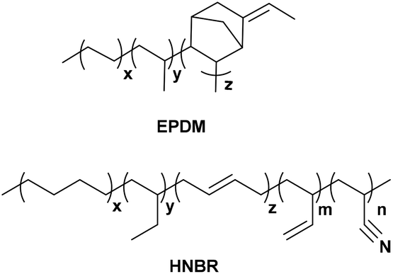
All simulations in this study were performed with Biovia Materials Studio software using the COMPASS (Condensed-phase Optimized Molecular Potentials for Atomistic Simulation Studies) forcefield.19,20 Molecular structures of HNBR and EPDM are shown in Scheme 1. HNBR chains contain acrylonitrile (ACN, 36 wt%), three types of butadiene repeat units (1 wt% in total): trans-1,4, cis-1,4, and 1,2 butadiene, and saturated 1,4 (55 wt%) and 1,2 butadiene (8 wt%). EPDM chains have ethylene (54 wt%), propylene (38 wt%) and 5-ethylidene norbornene (ENB, 8 wt%). The non-bonded force field parameters for HNBR and EPDM are presented in ESI Table S1.† In the following, the generation of HNBR and EPDM cells and their equilibration are summarized. Initially, polymer chains were built using the random copolymer option and geometry optimization was performed using the Forcite Module. In order to ensure that the number of atoms in the HNBR and EPDM simulation boxes were similar, single HNBR and EPDM chain contained 40 and 50 monomer units, respectively. Then, A periodic model of the copolymer, comprising of 8 polymer chains in each cubic unit cell (simulation box), was constructed. Annealing was performed by the NVT dynamics procedure through heating and cooling the system at 1 atm in the temperature range of 300 to 600 K in steps of 50 K. The time of dynamics was 10![[thin space (1/6-em)]](https://www.rsc.org/images/entities/char_2009.gif) 000 ps at each temperature, and the integration step was 10−3 ps. Interactions of nonbond, van der Waals and electrostatic forces, were calculated using an atom-based summation method and Ewald summation method, respectively.21 The annealed cell was later put through a stage-wise equilibration procedure. First the cell was heated to 600 K, and then the temperature was decreased in several stages to 400 K in steps of 50 K. After this, the temperature was decreased in several stages to 300 K in steps of 25 K. Each stage consisted of two consecutive runs in the following order: (i) an NVT run at a specific temperature, and (ii) an NPT run at 1 atm and a specific temperature. Each of the two consecutive runs in all stages was applied for 1000 ps and the integration step was 10−3 ps. The aim of the procedure was to obtain a refined system that would relax at the experimental density of the amorphous polymer at 1 atm and 300 K. Finally, the cell was relaxed by consecutive NVT (at 300 K) and NPT dynamics (at 1 atm and 298 K) to ensure that a constant density has been reached. This final equilibration step was carried out for 1000 ps using 10−3 ps time steps. A density versus time profile was obtained, and the average density of the last 100 frames was calculated. Two criteria were used to determine the equilibrium of the system: (1) the density and cell length of the system remained stable for a long time; (2) the fluctuation of energy was lower than 10%.22 The plots of density, cell length and energy versus simulation time in the NPT for EPDM and HNBR are shown in ESI Fig. S1 and S2.† Fig. S1 and S2† show that the EPDM and HNBR systems have reached equilibrium states.
000 ps at each temperature, and the integration step was 10−3 ps. Interactions of nonbond, van der Waals and electrostatic forces, were calculated using an atom-based summation method and Ewald summation method, respectively.21 The annealed cell was later put through a stage-wise equilibration procedure. First the cell was heated to 600 K, and then the temperature was decreased in several stages to 400 K in steps of 50 K. After this, the temperature was decreased in several stages to 300 K in steps of 25 K. Each stage consisted of two consecutive runs in the following order: (i) an NVT run at a specific temperature, and (ii) an NPT run at 1 atm and a specific temperature. Each of the two consecutive runs in all stages was applied for 1000 ps and the integration step was 10−3 ps. The aim of the procedure was to obtain a refined system that would relax at the experimental density of the amorphous polymer at 1 atm and 300 K. Finally, the cell was relaxed by consecutive NVT (at 300 K) and NPT dynamics (at 1 atm and 298 K) to ensure that a constant density has been reached. This final equilibration step was carried out for 1000 ps using 10−3 ps time steps. A density versus time profile was obtained, and the average density of the last 100 frames was calculated. Two criteria were used to determine the equilibrium of the system: (1) the density and cell length of the system remained stable for a long time; (2) the fluctuation of energy was lower than 10%.22 The plots of density, cell length and energy versus simulation time in the NPT for EPDM and HNBR are shown in ESI Fig. S1 and S2.† Fig. S1 and S2† show that the EPDM and HNBR systems have reached equilibrium states.
 |
| | Scheme 1 The chemical structures of HNBR and EPDM. | |
In all runs, Nosé method was used for temperature control.23 In NPT runs, the pressure was controlled by Berendsen's method. During these simulations, the cutoff for the nonbonded interactions was taken as 15.5 Å both for HNBR and EPDM. The spline and buffer widths were 1 and 0.5 Å.
2.2 Glass transition temperature
The glass transition temperatures, Tg, of HNBR and EPDM were determined from the plot of specific volume (the reciprocal of density) versus temperature.24 NPT simulations were performed to determine polymer density over the range of 50 to 500 K at 50 K intervals. Each NPT simulation was performed for 500 ps. The glass transition temperature was determined as the temperature at which there was a change of slope in the specific volume versus temperature plot using a segmented regression analysis.24
2.3 Solubility parameter
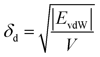
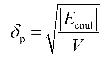
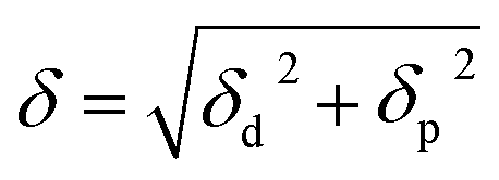
The solubility parameters, δ, of HNBR and EPDM were calculated using the van der Waals and coulombic energy of interactions (EvdW and Ecoul, respectively) and the molar volume, V, which is the ratio of the average molecular weight and the density of the polymer (obtained using the procedure described in Section 2.1).24 The dispersion and polar components of δ were calculated using| |
 | (1) |
and| |
 | (2) |
respectively, and the total solubility parameter, δ, was obtained from| |
 | (3) |
The atom-based summation and Ewald summation methods were used to calculate the above EvdW and Ecoul interaction energies, respectively. The average solubility parameter was calculated from the last 100 equilibrated frames.
2.4 Free volume
The free volume and occupied volume of HNBR and EPDM cells were calculated using the Connolly task. The simulated fractional free volumes (FFV) of the polymers are dependent on the chosen Connolly radius since these are used as the probe particles. The void distribution was estimated by a method previously used for micro-crystalline materials.25,26 Specifically, the simulation cell was divided into three-dimensional fine grids with a size of approximately 0.1 Å. The void size at a grid was determined as the diameter of the maximum cavity that encloses the grid and additionally has no overlap with any polymer atom.
2.5 Determination of local mobility of polymer chains
A segmental vectorial autocorrelation function (VACF) was used to investigate both main-chain and side-chain flexibility. By defining a vector, u(t0), that represents the orientation of a chain segment (backbone or side chain) at a given time, t0, the angle by which the orientation changes over time, t, is given as27| | |
m(t) = 〈u(t0)u(t0 + t)〉
| (4) |
Ensemble averages were computed over 1000 ps of NVE dynamics. The main-chain vector was chosen as extending from C(i) to C(i + 1) in the main chains. For the side chain, the vector was chosen to extend from C(i) to the nitrogen atom of the –CN group attached to C(i) (i.e. C(i)–C–N) in HNBR and from C(i) to the carbon atom of the methyl group attached to C(i) (i.e. C(i)–C) in EPDM.
2.6 MD simulation for diffusion coefficients
Ten molecules of the diffusing species (that is, the penetrant molecules, H2, N2, O2, CH4 or CO2) were placed into the equilibrated simulation box (as described in Section 2.1). This was followed by minimization of the potential energy of the penetrant/polymer system using ‘‘smart minimizing method’’ run for 50000 steps.28 Then, annealing was performed by the NVT dynamics procedure through heating and cooling the system at 1 atm in the temperature range of 300 to 600 K in steps of 50 K. The time of dynamics was 8000 ps at each temperature. The resulting structure was then equilibrated by NVT and NPT simulations at 298 K in order to ensure that its minimized total energy remained approximately constant with respect to the simulation time.
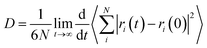
Diffusion coefficients of penetrant in the equilibrated polymer structure were determined from MD simulations. An NVE simulation of the system was performed for 10000 ps. A time step of 10−3 ps was used. The diffusion coefficients can be calculated by means of the Einstein relation29,30
| |
 | (5) |
where
N is the number of penetrants,
ri(0) and
ri(
t) are the initial and final positions of the center of mass of penetrant
i over the time interval
t, and 〈|
ri(
t) −
ri(0)|
2〉 is the averaged mean-square displacement (MSD) of the penetrant. The diffusion coefficient was determined from the slope of MSD
versus time data. In this work, MSD of H
2, O
2, N
2, CO
2 and CH
4 were calculated from the trajectories of ten penetrant molecules in the rubber microstructures.
2.7 Grand canonical Monte Carlo (GCMC) simulation for sorption isotherm
The equilibrated cell was used for GCMC simulations employing the standard Metropolis algorithm using the “Sorption Isotherm” module.31 Both the polymer framework and the penetrant molecules were treated as rigid bodies. The degrees of freedom of the system were accordingly specified by the center-of-mass position and orientation of the molecules. Metropolis sampling was used for inserting or deleting permeant molecules as well as accepting or rejecting their translational and rotational configurational moves. The COMPASS force field and force field assigned partial charges on atoms were used. The Ewald summation method was used for electrostatic interactions, and atom-based summation was used for van der Waals interactions. A VTμ simulation was performed at each fixed pressure and 298 K. The pressure of the penetrant gas was varied from 10 to 160 kPa. For each pressure value, 105 equilibration steps were first performed to ensure proper relaxation of the polymer chains in response to the insertion of the penetrant molecule, following which 106 steps of production run were carried out. The simulation output was the number of penetrant molecules present in the simulation cell at equilibrium. The sorption isotherm can be obtained in the form of a plot of the concentration of sorbed gas, C, as a function of pressure at constant temperature. The solubility coefficient, S, is then obtained from the limiting slope of the sorption isotherm at zero pressure as32| |
 | (6) |
where C is in units of cm3 (STP) cm−3 (polymer) and p is pressure.
3. Results and discussion
3.1 Validation of simulation models
The computed densities (ρ), glass transition temperatures (Tg) and solubility parameters (δ) of HNBR and EPDM are shown in Table 1. The experimental values in the literatures are also shown for comparison. The data obtained from MD simulations in this work match closely to experimental values reported in the literature, with the errors less than 8%. The density, glass transition temperature and solubility parameter of HNBR are higher than those of EPDM. This is due to the strong interactions of polar –CN groups in the HNBR molecular chains, which improve the packing density of polymer chains and the interchain cohesion. Based on these data, we can say that the equilibrated EPDM and HNBR cells reasonably represent their structures.
Table 1 Estimated and experimental values of densities, Tg and solubility parameters for HNBR and EPDM
| Rubber |
|
ρ (g cm−3) |
Tg (K) |
δ (MPa1/2) |
| Experimental values are obtained from ref. 33. Experimental values are obtained from ref. 34–36. |
| HNBR |
This work |
0.93 ± 0.02 |
243 ± 5 |
18.2 ± 0.2 |
| Experimenta |
0.95 |
248 |
19.7 |
| EPDM |
This work |
0.88 ± 0.02 |
219 ± 5 |
15.1 ± 0.3 |
| Experimentb |
0.86 |
218 |
16–16.5 |
3.2 Gas diffusion
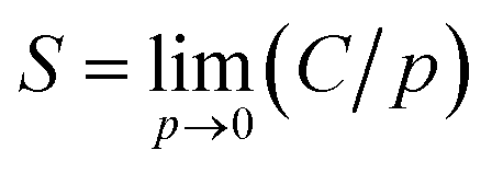
Fig. 1(a) and (b) present the log–log plot for MSD of different gas molecules (H2, N2, O2, CO2, CH4) in HNBR and EPDM as a function of time, respectively. The thin dashed lines in Fig. 1 represent the transition from the nonEinstein (anomalous) diffusion regime to the Einstein diffusion regime. The nearly unit slope of log(MSD) versus log(t) plot indicates that a normal (Einstein) diffusion regime is attained.34 The diffusion coefficients at 298 K obtained from the MSD plots (Einstein diffusion regime) for the five gases in HNBR and EPDM are shown in Table 2. Teplyakov and Meares have developed the following correlation between the diffusion coefficients of penetrant gases and their effective diameters.37| | |
logD = K1 − K2deff2
| (7) |
Here, deff is the effective penetrant diameter. The correlation coefficients K1 and K2 depend on the chemical and physical properties of the polymer matrices. This correlation holds for both glassy and rubbery polymers, as well as for homopolymers and copolymers.38
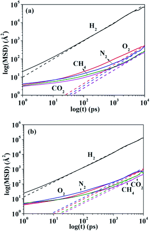 |
| | Fig. 1 Mean-square displacement of penetrant molecules in (a) HNBR and (b) EPDM as a function of time. The thin dashed lines are fitted to diffusion data in the Einstein region. | |
Table 2 Simulated and experimental diffusion coefficients, solubility coefficients and permeability for penetrant molecules in HNBR and EPDM
| Gas |
Da |
Sb |
Pc |
| HNBR |
EPDM |
HNBR |
EPDM |
HNBR |
EPDM |
| Units of (10−6 cm2 s−1). Units of (10−6 cm3 (STP) cm−3 pa−1). Units of (10−12 cm2 cm3 (STP) cm−3 s−1 pa−1). The experimental data of EPDM and NBR are obtained from ref. 15 and 40. |
| Simulated results |
| H2 |
76.1 ± 1 |
87.4 ± 2 |
0.34 ± 0.01 |
0.68 ± 0.01 |
25.87 ± 1 |
59.43 ± 2 |
| O2 |
1.58 ± 0.02 |
2.5 ± 0.01 |
1.63 ± 0.01 |
3.90 ± 0.02 |
2.58 ± 0.1 |
9.75 ± 0.5 |
| N2 |
0.72 ± 0.001 |
2.3 ± 0.01 |
0.49 ± 0.01 |
1.71 ± 0.01 |
0.35 ± 0.01 |
3.93 ± 0.1 |
| CH4 |
0.61 ± 0.001 |
1.8 ± 0.01 |
0.82 ± 0.01 |
5.31 ± 0.01 |
0.50 ± 0.01 |
9.56 ± 0.1 |
| CO2 |
0.52 ± 0.001 |
0.75 ± 0.002 |
39.0 ± 0.5 |
13.4 ± 0.5 |
20.28 ± 0.5 |
10.1 ± 0.5 |
|
| Experimental resultsd |
| H2 |
2.430 |
8.0 |
0.217 |
0.394 |
0.535 |
3.15 |
| O2 |
0.136 |
0.65 |
0.533 |
1.03 |
0.072 |
0.66 |
| N2 |
0.064 |
0.55 |
0.276 |
0.691 |
0.018 |
0.38 |
| CH4 |
|
0.23 |
|
3.10 |
|
0.71 |
| CO2 |
0.038 |
0.36 |
14.70 |
11.1 |
0.559 |
4.00 |
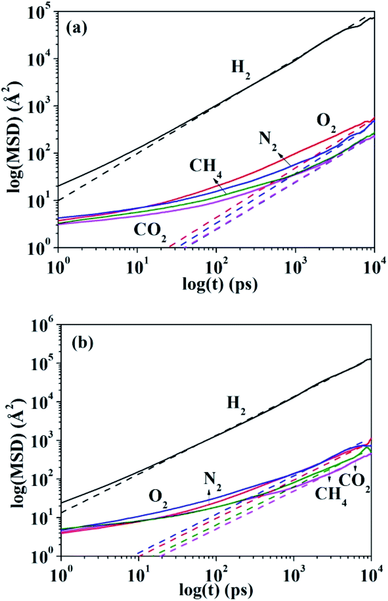
The logarithms of D are plotted against deff2 of the penetrant gases for HNBR and EPDM in Fig. 2. The effective diameters used for the plot in Fig. 2 are those tabulated by Teplyakov and Meares from a comparison of the diffusion coefficients of various gases with those for inert gases in different polymers.39 In Fig. 2 and Table 2, the diffusion coefficients for HNBR and EPDM in this work are also compared with the available experimental data of NBR and EPDM,15,40 reported in the literatures. It can be seen that the diffusion coefficients of penetrants in HNBR and EPDM, calculated using the MD simulations of the present study, show similar trends as the experimental values reported in the literatures. However, they are about one order of magnitude higher than the respective experimental values. Higher simulated diffusion coefficients for HNBR compared to experimental values are also reported by Krishnan.17 The higher D may be attributed to the fact that the MD simulations are for uncross-linked chains of rubber, whereas the experimental values are for crosslinked rubbers. The diffusion coefficients are evidently lower in a cross-linked polymer than in the analogous low-molecular weight un-cross-linked copolymer of identical composition.17 The simulated D(CO2) (5.2 × 10⁻⁷ cm2 s−1) for HNBR in this work agrees well with the simulated D(CO2) (3.7 × 10⁻⁷ cm2 s−1) for HNBR reported by Krishnan.17
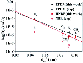 |
| | Fig. 2 Experimental and simulated diffusion coefficients as a function of the squared effective penetrant diameter (deff2) for HNBR, NBR and EPDM. The experimental data for EPDM and NBR are obtained from ref. 15 and 40, respectively. (▲) Simulated and (△) experimental diffusion coefficients for EPDM; (●) simulated diffusion coefficients for HNBR and (○) experimental diffusion coefficients for NBR. | |
The line in Fig. 2 represent the least squares fit of the simulated data for HNBR and EPDM in this work according to eqn (7). It can be seen that the simulated data for HNBR and EPDM in this work conform reasonably well to the correlation given by eqn (7). The results show that K2 (HNBR) > K2 (EPDM). Teplyakov and Meares have reported that K2 increases as the cohesive energy density (CED = δ2) of the polymer matrices increase.37 Our results are consistent with this trend. The gas diffusion coefficients in HNBR and EPDM follow the same order D(H2) > D(O2) > D(N2) > D(CH4) > D(CO2), while the effective diameter order is H2 < O2 < CO2 < N2 < CH4. The prediction of diffusivity based on the effective diameter values for the CO2 is anomalous. Obviously, the D(CO2) value is lower compared with those of N2 and CH4, which is not associated with their effective diameter. This is due to the linear shape of CO2 that takes more time to travel through the cavities in the polymer matrix.41 In the case of HNBR, the more polar CO2 has favorable interaction with the polar –CN groups in the HNBR chains, which binds itself with the HNBR matrix.42 This type of interaction is not present among CH4, N2, O2 and H2 with the HNBR. The above two factors lead to the decrease of D(CO2) in HNBR and EPDM.
The gas diffusion coefficients of HNBR are lower than EPDM and the differences between the diffusion coefficients of the two rubbers increase as the effective penetrant diameter increases. In the following, the effect of free volume, chain packing and local chain mobility on gas diffusivity properties of EPDM and HNBR matrices will be discussed.
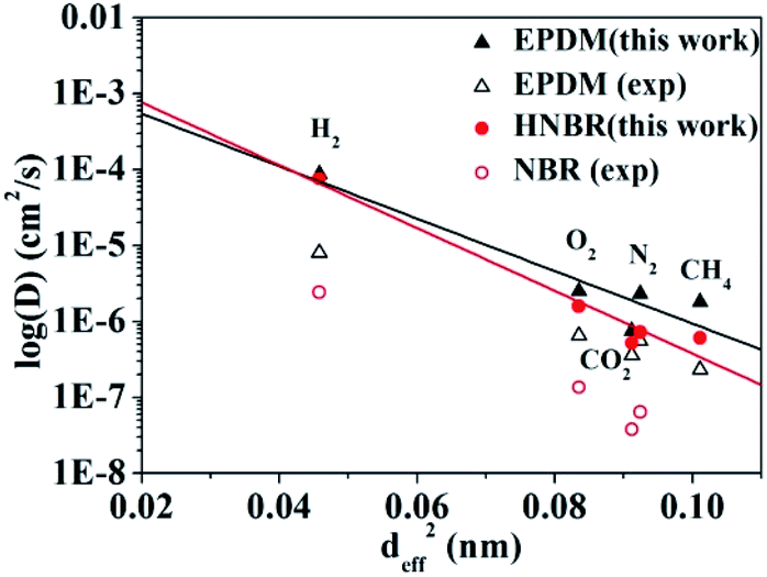
3.2.1 Free volume. The size and distribution of free volume in polymer membranes play a substantially important role in diffusion and sorption of gas species. The morphology of free volume in HNBR and EPDM, including size, shape, and connectivity, are shown in Fig. 3. The free volumes, denoted by the blue regions, were estimated for a probe of radius 0.5 Å. We can quantitatively correlate free volume morphology with gas diffusivity of polymer membranes. HNBR contains more smaller and discontinuous voids and shows low gas diffusivity. The polar –CN groups in HNBR increase the interchain cohesion, resulting in the tight packing of the polymer chains. As a result, the gas diffusivity decreases. Compared with HNBR, EPDM has the more large voids and well-connected network. This is mainly attributed to the presence of norbornene in EPDM, which reduces the chains packing and leads to high gas diffusivity.
 |
| | Fig. 3 Free volume morphologies in (a) HNBR and (b) EPDM matrices estimated for a probe radius of 0.5 Å. | |
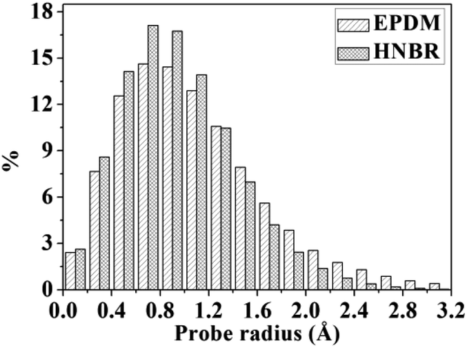
A detail analysis for the distribution of void size is shown in Fig. 4. It is already established that the free volume distributions in amorphous polymers are an important aspect of their transport behavior toward small and medium-sized penetrant molecules.43 The figure shows the monomodal size distribution with maximum opportunity at free volume radius of approximately 0–1.4 Å, which indicates the total extension of an interconnected free volume region.44 It is significant to note that compared with EPDM, HNBR has more voids with radius < 1.3 Å but less voids with radius > 1.3 Å. The number of voids with a volume larger than the diameter of gas molecules has a substantial influence on diffusivity. In comparison to EPDM, HNBR has less large voids, which leads to low gas diffusivity. It is shown before that the differences between the diffusion coefficients of HNBR and EPDM increase as the effective penetrant diameter increases. This is also due to the less large voids in HNBR. The dependence of fractional free volume (FFV) on the size of a spherical probe molecule is shown in Fig. 5. As expected, the FFV shows a steep decrease when the probe size is increased. For reference, the effective radii reported by Teplyakov and Meares for the five gases (H2, O2, N2, CO2 and CH4) considered in this study are indicated on the figure. It is evident that the volumes for these gases in HNBR are lower than those in EPDM, which results in lower gas diffusion coefficients of HNBR.
 |
| | Fig. 4 Distributions of void radius in HNBR and EPDM matrices. | |
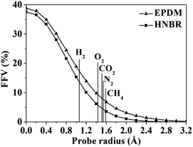 |
| | Fig. 5 Fractional free volume (FFV) of HNBR and EPDM as a function of probe radius. The effective radii of five gases are indicated by vertical lines. | |
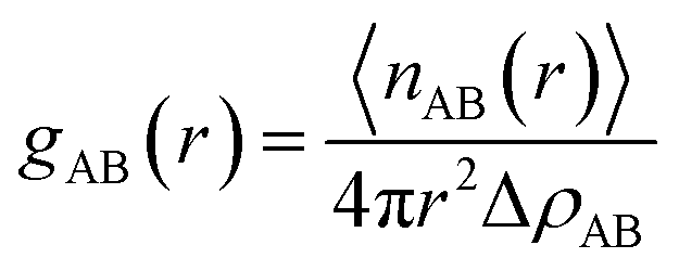
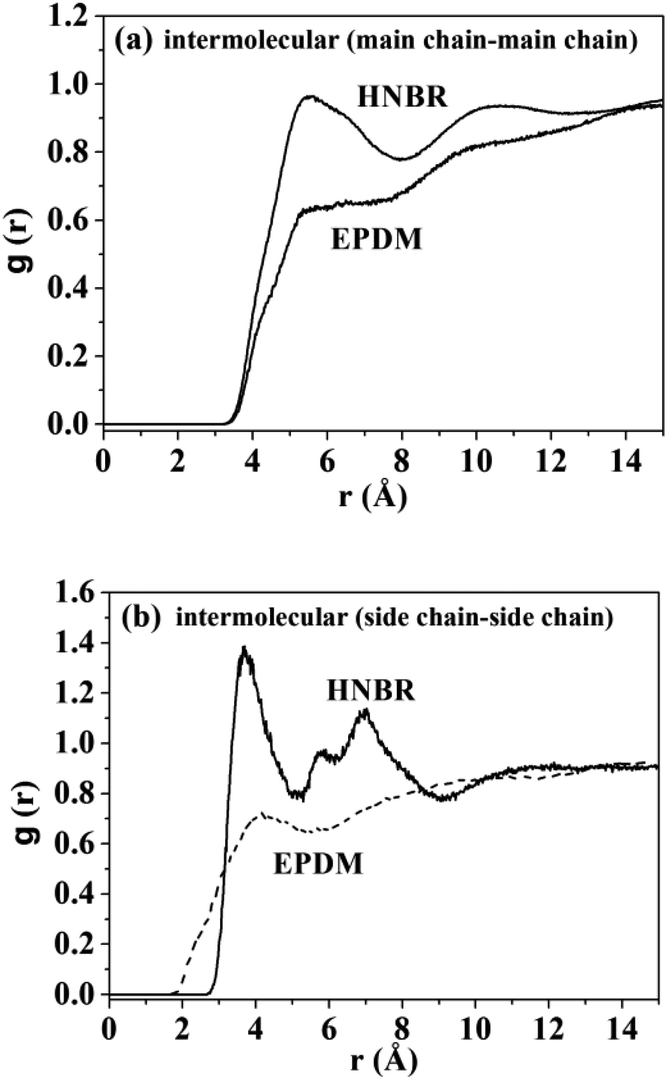
3.2.2 Pair correlation functions. To obtain further insights about chain packing, the pair correlation function, g(r), is calculated for HNBR and EPDM. The g(r) refers to a measure of the probability that, given the presence of an atom at the origin of an arbitrary reference frame, there will be an atom with its center located in a spherical shell of infinitesimal thickness at a distance r from the reference atom. The g(r) is calculated by the average of the static relationship of every given pair of particles AB using the following equation:
where 〈nAB(r)〉 is the average number of atom pairs between r and r + Δr, and ΔρAB is the density of atom pairs of type AB. Fig. 6(a) and (b) show the intermolecular pair correlation functions for the main chain atoms and for the side chain atoms, respectively. Here the main chains intermolecular g(r) refers to the interactions of the carbon atoms of the main chain with carbon atoms on the other main chain. The side chains intermolecular g(r) involves the interactions of the nitrogen atoms in the –CN for HNBR and the carbon atoms in the methyl for EPDM. The g(r) is averaged over 4000 snapshots between 0 and 4 ns. From Fig. 6(a), it can be seen that the intermolecular g(r) shows a peak around 5.4 Å for HNBR and EPDM. The magnitude of g(r) at this peak for HNBR is higher than that for EPDM, which is consistent with the order of the CED of the two rubbers. A larger value of g(r) indicates that the number of nearest neighbors within a distance r from a central atom is bigger. This means that the main chains are more closely packed in HNBR compared to EPDM, which agrees with the free volume results. Furthermore, in Fig. 6(b) g(r) for side chains of HNBR and EPDM are compared. Here, it is also seen that the side chains are more closely packed in HNBR. In summary, Fig. 6 indicates that the molecular packing of the polymer chains is tighter in HNBR than EPDM, a fact that is related to the higher CED in HNBR and that may at the same time contribute to the lower diffusivity in HNBR.
 |
| | Fig. 6 Pair correlation functions: (a) chain–chain intermolecular g(r) for HNBR and EPDM; (b) intermolecular g(r) for side chains of HNBR and EPDM. | |
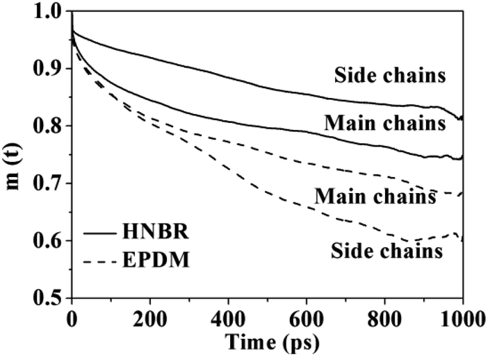
3.2.3 Local mobility of polymer chains. Plots of main-chain and side-chain VACFs of HNBR and EPDM are shown in Fig. 7. The curves show a continual decay, which is a typical characteristic of rubbery polymers. In comparison to EPDM, HNBR exhibits much slower relaxations of the main and side chain vectors, which means the chain mobility of HNBR is poorer than that of EPDM. This is also a reason for the slower gas diffusion observed in HNBR. The channel formation for the gas molecules to permeate is dependent on the mobility of the polymer chains.45 The polar –CN groups in HNBR increase the interchain cohesion, thus resulting in poor chain mobility. The decreased chain mobility in HNBR decreased the extent of channel formation for gas diffusion, leading to the slower gas diffusion. The side-chain mobility is lower than main-chain in HNBR. This indicates that mobility of the side chain of HNBR is restricted, which is also due to the interaction between polar –CN groups in HNBR.
 |
| | Fig. 7 Plots of the main-chain and side-chain vectorial autocorrelation function (VACF) for HNBR and EPDM. | |
3.3 Gas solubility
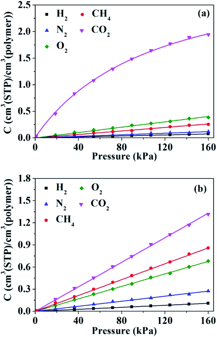
The sorption isotherms for penetrant gases in HNBR and EPDM obtained from GCMC simulations are shown in Fig. 8. The isotherms of H2, N2, O2 and CH4 in HNBR and EPDM appear to be linear within the pressure range shown, indicating equilibrium conforming to Henry's law. The sorption isotherm of CO2 in EPDM is linear; however, that in HNBR is concave to the pressure axis. Sorption isotherms in rubbery polymers often exhibit linearity (Henry's law behavior) or an upward concavity (concavity with respect to the ordinate axis).46 Concavity with reference to the abscissa (pressure) axis is generally observed for gas sorption in amorphous glassy polymers having pre-existing microvoids and is characterized using the Langmuir adsorption or the dual sorption models.47 The downward concavity of sorption isotherms for CO2 indicates adsorption of gas molecules at specific sites on the polymer chains. Similar downward concavity was reported by Krishnan17 and Nunes et al.48 for the sorption of CO2 in fluorinated HNBR and natural rubber–cellulose composites, respectively. The sorption isotherm of CO2 in HNBR conforms well to the dual mode sorption model, and the other sorption isotherms (H2, N2, O2 and CH4) fit well to Henry's model. The curves in Fig. 8 represent the fit lines. Solubility coefficients obtained from the isotherms are listed in Table 2.
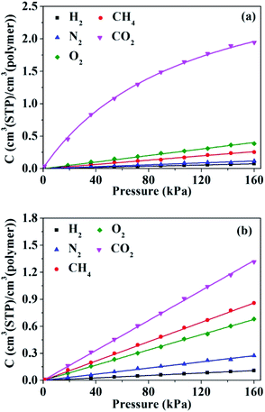 |
| | Fig. 8 Pressure dependence of the concentration of gases in (a) HNBR and (b) EPDM. | |
The solubility of a gas in a certain polymeric membrane depends on several factors including the condensability of the gas, the polymer–penetrant interactions, and the available free volume. The critical temperature, boiling point and effective Lennard-Jones interaction constant (ε/k) are usually used to measure the condensibility of gases. Teplyakov and Meares reported a correlation between effective Lennard-Jones interaction constant and solubility as follows:37
| | |
logS = K3 + K4(ε/k)
| (8) |
where
K3 and
K4 are polymer-specific.
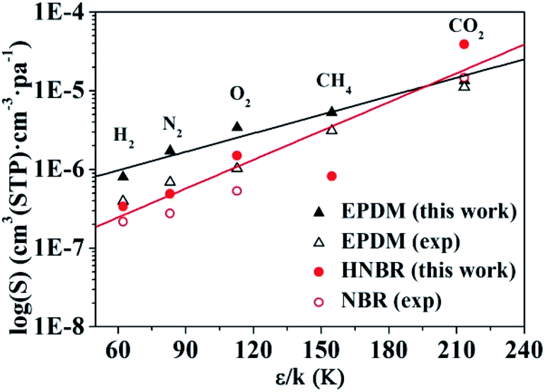
Values of solubility coefficients for five gases (H2, O2, N2, CO2, and CH4) in HNBR and EPDM obtained from GCMC simulation are plotted against ε/k in Fig. 9. In Fig. 9 and Table 2, the solubility coefficients for HNBR and EPDM in this work are compared with the available experimental data, reported in the literatures.15,40 The solubility coefficients for HNBR and EPDM in the present study show similar trends as the experimental values. However, they are about 1.1–3.7 times higher than the respective experimental values. The simulated S(CO2) (3.9 × 10⁻⁵cm3 (STP) cm−3 pa−1) for HNBR in this work shows good agreement with the simulated S(CO2) (3.0 × 10⁻⁵ cm3 (STP) cm−3 pa−1) for HNBR reported by Krishnan.17 Khawaja et al. also reported that the simulated solubilities of He and CO2 in NBR were overestimated with respect to experimental values by a factor of between 2 and 5.16 The higher simulated solubility coefficients compared with experimental values may be due to the following two factors. As discussed before, one factor is that the HNBR chains in simulation are un-cross-linked, whereas those in experiment are crosslinked. Another factor may be the sampling issues in these simulations. It may be the case that in reality the length scale over which the polymer is homogeneous is longer than the typical dimensions of a molecular simulation, for example, due to the presence of submicroscopic voids.49
 |
| | Fig. 9 Experimental and simulated solubility coefficients as a function of effective Lennard-Jones interaction constants for HNBR and EPDM. The experimental data for EPDM and NBR are obtained from ref. 15 and 40, respectively. | |
The lines in Fig. 9 represent a least squares fit of the simulated data for HNBR and EPDM in this work according to eqn (8). The K4 values increase in the order: K4 (HNBR) > K4 (EPDM). Teplyakov and Meares have reported that the polar matrices have higher K4 values.37 Our results are in conformity with this trend. The effective Lennard-Jones interaction constants (ε/k) of gases decrease in the order CO2 > CH4 > O2 > N2 > H2, and the solubility coefficients follow the order S(CO2) > S(O2) > S(CH4) > S(N2) > S(H2) for HNBR and S(CO2) > S(CH4) > S(O2) > S(N2) > S(H2) for EPDM. It can be seen that the trend of solubility coefficients of gases in EPDM is consistent with that of gases condensibility. However, the S(CH4) is lower than S(O2) in HNBR, which is not associated with their condensibility. The solubility coefficients of CH4, O2, N2 and H2 in HNBR are lower than those in EPDM, while S(CO2) of HNBR is higher than EPDM. This may be related to the polymer–penetrant interactions, which will be discussed in the following section.
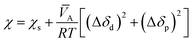
The Flory interaction parameter, χ, that characterizes the interaction energy between penetrant molecules, A, with the polymer can be estimated using eqn (9) based on the regular solution theory:
| |
 | (9) |
wherein
χs is the entropic contribution to the interaction parameter, approximately 0.34 according to Blanks and Prausnitz,
50 Δ
δd is the difference in the values of the dispersion components of the penetrant and polymer solubility parameters, and Δ
δp is the difference in the polar components of the penetrant and polymer solubility parameters.
![[V with combining macron]](https://www.rsc.org/images/entities/i_char_0056_0304.gif) A
A is the partial molar volume of the permeant molecules in the polymer matrix,
R is the gas constant, and
T is the absolute temperature.
Table 3 gives the dispersion and polar components,
δd and
δp, respectively, of the solubility parameter,
δ, of EPDM and HNBR, along with the solubility parameters
51 and partial molar volume
52 of five gases. Separate polar and hydrogen bonding components were reported by Hansen,
51 but a combined value is reported as
δp in
Table 3 (because hydrogen bonding is included in the electrostatic potential energy term, computed using partial atomic charges, in the COMPASS force field used in the present study).
Table 3 Solubility parameters and interaction parameters of HNBR, EPDM and gases at 298 K and 1 atm
| Gas |
δda |
δpa |
δ |
Ab |
χ(HNBR–gas) |
χ(EPDM–gas) |
| The dispersion and polar components of solubility parameter for gases are obtained from ref. 51. The partial molar volume of gases are obtained from ref. 52. |
| H2 |
5.1 |
0 |
5.1 |
28 |
2.435 |
1.413 |
| N2 |
11.9 |
0 |
11.9 |
35 |
1.375 |
0.467 |
| O2 |
14.7 |
0 |
14.7 |
28 |
0.949 |
0.345 |
| CH4 |
14.0 |
0 |
14.0 |
38 |
1.218 |
0.357 |
| CO2 |
15.7 |
8.5 |
17.9 |
46 |
0.399 |
1.490 |
| HNBR |
16.8 |
7.1 |
18.2 |
|
|
|
| EPDM |
14.8 |
0.7 |
14.8 |
|
|
|
The Flory interaction parameters, χ, calculated through eqn (9) are shown in Table 3. It can be seen that the Flory interaction parameters between gas molecules (CH4, O2, N2 and H2) with the HNBR are higher than those of EPDM. It is known that the higher χ is, the less compatible are the two components and the less satisfactorily does the gas dissolve.40 Hence, the lower solubility coefficients of CH4, O2, N2 and H2 in HNBR compared with those in EPDM may be due to the high χ, i.e. weak interaction between gases (CH4, O2, N2 and H2) with HNBR. In addition, the low FFV and less large free volume elements of HNBR in comparison with EPDM also contribute to the lower solubility coefficients of CH4, O2, N2 and H2 in HNBR. This is because that the size and number of cavities in HNBR is lower, which make it has fewer sites for the sorption of gases. The Flory interaction parameter between CO2 and HNBR is greatly lower than that of EPDM, which means the strong interaction between CO2 with HNBR. Carbon dioxide, which does not have a permanent dipole moment, does have a large quadrupole moment.53 The electrostatic interactions between CO2 and ACN monomer of HNBR favor the dissolution of CO2,42 leading to the high S(CO2) in HNBR. Compared with free volume, the polymer–penetrant interactions have a greater influence on the dissolution of CO2 in HNBR and EPDM.
3.4 Permeability
The permeability coefficient (P) can be given by the product of the diffusion coefficient and solubility coefficient as P = D × S. Table 2 and Fig. S3† present the permeability coefficients and selectivity of penetrant molecules in HNBR and EPDM. The selectivity of gas pairs was estimated by the ratio of permeability coefficients. It can be seen that the permeability increase in the same order P(H2) > P(CO2) > P(O2) > P(CH4) > P(N2) for HNBR and EPDM. The highest P(H2) in HNBR and EPDM is mainly due to its high diffusion coefficient, which is a result of the small molecular size of H2. The higher P(CO2) is mostly attributed to its high solubility coefficient. Except for CO2, all the other gases (H2, O2, N2 and CH4) show lower permeability coefficients in HNBR than those in EPDM. This is because that both the diffusion coefficients and solubility coefficients of H2, O2, N2 and CH4 in HNBR are lower than those in EPDM. Although the D(CO2) in HNBR is lower than that in EPDM, the S(CO2) in HNBR is much higher than that in EPDM, which results in the higher P(CO2) in HNBR. The high S(CO2) in HNBR is a result of the high compressibility of CO2 and strong interaction between CO2 and HNBR. From Fig. S3,† it can be seen that HNBR shows higher α(H2/N2), α(CO2/N2), α(CO2/CH4) and α(O2/N2) than EPDM.
4. Conclusions
Molecular dynamics and grand canonical Monte Carlo (GCMC) simulations were performed to study the diffusion and sorption of five gases (H2, N2, O2, CO2, CH4) in HNBR and EPDM. The relation between the diffusion coefficients and the effective penetrant diameter is confirmed by the results in HNBR and EPDM. The diffusion coefficients of five gases in HNBR are lower than EPDM. The presence of polar –CN groups in HNBR chains increases interchain cohesion and results in tight intermolecular packing, low free volume and poor chain mobility, which leads to the lower diffusion coefficients in HNBR. The solubility coefficients of CH4, O2, N2 and H2 in HNBR are lower, but that of CO2 in HNBR is higher than EPDM. The weak HNBR–penetrant interactions and low free volume of HNBR lead to the lower solubility coefficients of CH4, O2, N2 and H2 in HNBR, while the strong interaction between CO2 and HNBR contributes to the higher solubility coefficient of CO2 in HNBR. Except for CO2, all the other gases (H2, O2, N2 and CH4) show lower permeability coefficients in HNBR than those in EPDM. These molecular simulations provide important molecular-level details for the understanding of structures and gas transport properties between HNBR and EPDM.
Conflicts of interest
There are no conflicts to declare.
Acknowledgements
This work was supported by the NSAF (No. U1730142), the Natural Science Foundation of Hunan Province (No. 2018JJ3120) and the Student Innovation and Entrepreneurship Training Program of China (No. 201811535004, 201911535005).
References
- A. Ciesielski, An Introduction to Rubber Technology, Rapra Technology Limited, 1999 Search PubMed.
- L. L. Wang, Y. P. Tong, L. Q. Zhang and M. Tian, J. Appl. Polym. Sci., 2010, 116, 3184–3192 CrossRef CAS.
- E. E. B. Meuleman, J. H. A. Willemsen, M. H. V. Mulder and H. Strathmann, J. Membr. Sci., 2001, 188, 235–249 CrossRef CAS.
- N. K. Singha, S. Bhattacharjee and S. Sivaram, Rubber Chem. Technol., 1997, 70, 309–367 CrossRef CAS.
- H. Wang, L. Yang and G. L. Rempel, Polym. Rev., 2013, 53, 192–239 CrossRef CAS.
- Q. Yang and W. I. Whiting, J. Membr. Sci., 2018, 549, 173–183 CrossRef CAS.
- I. Tanis, D. Brown, S. Neyertz, R. Heck, R. Mercier, M. Vaidya and J.-P. Ballaguet, Comput. Mater. Sci., 2018, 141, 243–253 CrossRef CAS.
- S. G. Charati and S. A. Stern, Macromolecules, 1998, 31, 5529–5535 CrossRef CAS.
- Y. Tamai, H. Tanaka and K. Nakanishi, Macromolecules, 1994, 27, 4498–4508 CrossRef CAS.
- E. Kucukpinar and P. Doruker, Polymer, 2003, 44, 3607–3620 CrossRef CAS.
- E. Kucukpinar and P. Doruker, Polymer, 2006, 47, 7835–7845 CrossRef CAS.
- F. Müller-Plathe, S. C. Rogers and W. F. van Gunsteren, J. Chem. Phys., 1993, 98, 9895–9904 CrossRef.
- D. M. Whitley and D. B. Adolf, J. Membr. Sci., 2012, 415–416, 260–264 CrossRef CAS.
- Y. Li, Y. P. Wu, L. Q. Zhang, X. J. Wang, D. Y. Ren and S. Z. Wu, J. Appl. Polym. Sci., 2014, 40347, 1–7 Search PubMed.
- S. W. Rutherford, D. T. Limmer, M. G. Smith and K. G. Honnell, Polymer, 2007, 48, 6719–6727 CrossRef CAS.
- M. Khawaja, A. P. Sutton and A. A. Mostofi, J. Phys. Chem. B, 2017, 121, 287–297 CrossRef CAS PubMed.
- M. Luo, Z. A. Putnam, J. Incavo, M. Y. Huang, J. B. McLaughlin and S. Krishnan, Ind. Eng. Chem. Res., 2019, 58, 14823–14838 CrossRef CAS.
- R. H. Gee and R. H. Boyd, Polymer, 1995, 36, 1435–1440 CrossRef CAS.
- H. Sun, J. Phys. Chem. B, 1998, 102, 7338–7364 CrossRef CAS.
- H. Sun, P. Ren and J. Fried, Comput. Theor. Polym. Sci., 1998, 8, 229–246 CrossRef CAS.
- W. Smith, Comput. Phys. Commun., 1992, 67, 392–406 CrossRef CAS.
- J. Zhu, X. Y. Zhao, L. Liu, M. Song and S. Z. Wu, J. Appl. Polym. Sci., 2018, 135, 46202 CrossRef.
- S. A. Nosé, J. Chem. Phys., 1984, 81, 511–519 CrossRef.
- R. I. Venkatanarayanan, S. Krishnan, A. Sreeram, P. A. Yuya, N. G. Patel, A. Tandia and J. B. McLaughlin, Macromol. Theory Simul., 2016, 25, 238–253 CrossRef CAS.
- S. Ban and T. J. H. Vlugt, Mol. Simul., 2009, 35, 1105–1115 CrossRef CAS.
- S. Bhattacharya and K. E. Gubbins, Langmuir, 2006, 22, 7726–7731 CrossRef CAS PubMed.
- C. F. Fan, T. Cagin, W. Shi and K. A. Smith, Macromol. Theory Simul., 1997, 6, 83–102 CrossRef CAS.
- Introduction to polymer modeling: training manual, Version April 2006, Accelrys Software Inc., San Diego, 2006 Search PubMed.
- P. V. Pant and R. H. Boyd, Macromolecules, 1993, 26, 679–686 CrossRef CAS.
- T. R. Cuthbert, N. J. Wagner and M. E. Paulaitis, Macromolecules, 1999, 32, 5017–5028 CrossRef CAS.
- R. L. C. Akkermans, N. A. Spenley and S. H. Robertson, Mol. Simul., 2013, 39, 1153–1164 CrossRef CAS.
- J. R. Fried, M. Sadat-Akhavi and J. E. Mark, J. Membr. Sci., 1998, 149, 115–126 CrossRef CAS.
- W. Hofmann, Rubber Technology Handbook, Hanser Publishers, Munich Vienna New York, 1989 Search PubMed.
- Z. Y. Zhang and S. A. Lin, Macromol. Rapid Commun., 1995, 16, 927–933 CrossRef CAS.
- J. Yamabe and S. Nishimura, J. Appl. Polym. Sci., 2011, 122, 3172–3187 CrossRef CAS.
- J. Brandrup, E. H. Immergut, E. A. Grulke, A. Abe and D. R. Bloch, Polymer Handbook, Wiley, New York, 1999 Search PubMed.
- V. Teplyakov and P. Meares, Gas Sep. Purif., 1990, 4, 66–74 CrossRef CAS.
- E. Kucukpinar and P. Doruker, Polymer, 2003, 44, 3607–3620 CrossRef CAS.
- V. V. Teplyakov and S. G. Durgaryan, Polym. Sci. USSR, 1984, 26, 1678–1688 CrossRef.
- G. J. Van Amerongen, J. Polym. Sci., 1950, 5, 307–332 CrossRef CAS.
- D. Bera, P. Bandyopadhyay, S. Ghosh, S. Banerjee and V. Padmanabhan, J. Membr. Sci., 2015, 474, 20–31 CrossRef CAS.
- F. Rindfleisch, T. P. DiNoia and M. A. McHugh, J. Phys. Chem., 1996, 100, 15581–15587 CrossRef CAS.
- C. Nagel, K. Günther-Schade, D. Fritsch, T. Strunskus and F. Faupel, Macromolecules, 2002, 35, 2071–2077 CrossRef CAS.
- D. Hofmann, M. Entrialgo-Castano, A. Lerbret, M. Heuchel and Y. Yampolskii, Macromolecules, 2003, 36, 8528–8538 CrossRef CAS.
- S. Seethamraju, P. C. Ramamurthy and G. Madras, ACS Appl. Mater. Interfaces, 2013, 5, 4409–4416 CrossRef CAS PubMed.
- T. C. Merkel, V. I. Bondar, K. Nagai, B. D. Freeman and I. Pinnau, J. Polym. Sci., Part B: Polym. Phys., 2000, 38, 415–434 CrossRef CAS.
- D. R. Paul, in Encyclopedia of Membranes, ed. E. Drioli and L. Giorno, Springer Berlin Heidelberg, Berlin, Heidelberg, 2016 Search PubMed.
- R. C. Reis Nunes, M. López-González and E. Riande, J. Polym. Sci., Part B: Polym. Phys., 2005, 43, 2131–2140 CrossRef.
- A. N. Gent, J. Appl. Phys., 1969, 40, 2520–2525 CrossRef CAS.
- R. F. Blanks and J. M. Prausnitz, Ind. Eng. Chem. Fundam., 1964, 3, 1–8 CrossRef CAS.
- C. M. Hansen, in Hansen Solubility Parameters: A User's Handbook, ed. C. M. Hansen, Taylor & Francis Group, Boca Raton, FL, 2007 Search PubMed.
- T. C. Merkel, V. I. Bondar, K. Nagai, B. D. Freeman and I. Pinnau, J. Polym. Sci., Part B: Polym. Phys., 1998, 38, 415–434 CrossRef.
- S. A. Stern, J. Membr. Sci., 1994, 94, 1–65 CrossRef CAS.
Footnote |
| † Electronic supplementary information (ESI) available. See DOI: 10.1039/d0ra00192a |
|
| This journal is © The Royal Society of Chemistry 2020 |
Click here to see how this site uses Cookies. View our privacy policy here. 
 Open Access Article
 This Open Access Article is licensed under a Creative Commons Attribution-Non Commercial 3.0 Unported Licence
 *a,
Juying Wub,
Ding Wua,
Xiang Zhanga,
Xiaoye Hec,
Zhihong Shea,
Ren Heb and
Hailiang Zhang
*a,
Juying Wub,
Ding Wua,
Xiang Zhanga,
Xiaoye Hec,
Zhihong Shea,
Ren Heb and
Hailiang Zhang