
 Open Access Article
 This Open Access Article is licensed under a Creative Commons Attribution-Non Commercial 3.0 Unported Licence
A comparative study on the mechanical and reactive behavior of three fluorine-containing thermites
Jiaxiang Wu a,
Qiang Liua,
Bin Fengb,
Shuangzhang Wua,
Sheng Zhanga,
Zhenru Gaoa,
Qin Yina,
Yuchun Li*a,
Liming Xiaoa and
Junyi Huang*a
a,
Qiang Liua,
Bin Fengb,
Shuangzhang Wua,
Sheng Zhanga,
Zhenru Gaoa,
Qin Yina,
Yuchun Li*a,
Liming Xiaoa and
Junyi Huang*a
aCollege of Field Engineering, Army Engineering University of PLA, Nanjing, 210007, China. E-mail: liyuchunmail@163.com; huangjunyi357@163.com
bChina Huayin Ordnance Test Center, Huayin, 714200, China
First published on 4th February 2020
Abstract
Thermite serves as a kind of representative energetic material, which is extensively applied in the civil and military fields. In this paper, PTFE/Al/Fe2O3, PTFE/Al/MnO2 and PTFE/Al/MoO3, solid fluorine-containing thermite with different PTFE content, were successfully fabricated by referring to the traditional thermite and adding PTFE as a binder or matrix. Quasi-static compression tests were performed to investigate the mechanical and reactive behavior of fluorine-containing thermite. SEM and XRD were employed to analyze and characterize the energetic composites and reaction residuals. The results show that all types of fluorine-containing thermite exhibited different mechanical behavior. PTFE/Al/MnO2 exhibited the lowest yield strength and strain hardening modulus, but the highest compressive strength and toughness. With the increase of PTFE content, the strength of fluorine-containing thermite improved. No reaction occurred when the PTFE content was 60 vol%, while fluorine-containing thermite with a PTFE content of 80 vol% experienced a severe exothermic reaction under quasi-static compression. The ignition of PTFE/Al/MoO3 and PTFE/Al/Fe2O3 actually attributed to the reaction of Al and PTFE, and the reaction between Al and Fe2O3 or MoO3 was not excited due to the insufficient input energy. The thermite reaction between Al and MnO2, as well as the reaction of MnO2 and PTFE, was induced because PTFE/Al/MnO2 possessed excellent ductility and absorbed the most energy during compression, accompanied with the production of Mn and MnF2.
1 Introduction
Thermite is a kind of representative energetic material, which is composed of aluminum powder mixed with metal oxide with strong oxidability. Under the function of heat or mechanical force, thermite can experience violent oxidation–reduction reactions and release a large amount of heat.1–3 Because of its high energy density, flexible formulation, good safety and high adiabatic temperature, thermite has a broad application prospect. In the civil field, thermite is generally used in metal welding, flame cutters and thermal batteries;4,5 in the military field, it is widely adopted as the additive of combustion agents, ignition powder, high-energy charge and solid rocket propellants.6,7Research on the application of thermite has received extensive attention. However, there are some urgent problems in the application of thermite, such as the low activity and poor energy release rate of micro thermite, the insufficient mechanical properties of the prepared thermite grain, and the lack of corresponding mechanical strength. Therefore, at present, the research focus of thermite is mainly in two aspects. One is to prepare nano thermite, in addition to the performance of micro thermite, nano thermite owns other performance advantages, including closer to ideal detonation, higher energy release rate and higher combustion (energy conversion) efficiency, so this research direction mainly focuses on the preparation method, ignition performance, thermal performance and combustion performance of nano thermite, and has obtained many significant results.8–10 The other is to add polymers to the thermite as binder. This idea is mainly through adding polymer into the thermite as the matrix, so that the material has better mechanical properties and higher sensitivity, and it is easy to prepare using mold processing to adapt to different industrial and military needs.11–13
In recent years, a kind of new-type thermite which use fluorine-containing substances as oxidants and Al as reducing agents has attracted great attention, such as Al/polyvinylidene fluoride (PVDF) and Al/polytetrafluoroethylene (PTFE).14–17 Fluorine atom is the most negative in all elements. When fluoropolymers decomposes under heat, it will release fluorine-containing radicals with strong oxidation. Because the melt viscosity of PTFE is extremely high, and the fluorine content of PTFE is 76%, which is the highest among all fluoropolymers,18 PTFE is very suitable as binder and oxidant in thermite system. Feng et al.19,20 reported a violent reaction phenomenon of Al/PTFE mixtures treated by a specific sintering process under quasi-static compression. Based on this finding, the effects of sintering temperature and composition ratio on the quasi-static reaction of Al/PTFE were ascertained. Wu et al.21 studied the influence of Al particle size on mechanical properties of Al/PTFE composites, the results show that with the increase of Al particle size, the strength of the composites declined monotonously, and the toughness rose firstly and subsequently decreased. Ding et al.22 utilized a new energy release testing device to investigate the energy release ability of PTFE/Al/CuO. It was found that with the increase of the content of Al/CuO thermite, the energy release rate of the material increased significantly, and because of the larger specific surface area, the ignition energy of nano-scale materials decreased, resulting in that the energy release ability of the nano-scale materials was higher than that of micron-scale materials. Consequently, adding PTFE as binder into the traditional oxide thermite to prepare structural fluorine-containing thermite can not only give full play to the advantages of traditional thermite, but also provide excellent mechanical strength for materials. Most importantly, PTFE can also be served as oxidant to react with Al and promote the energy release of thermite system.23–25 Fluorine-containing thermite combines the characteristics of traditional thermite and metal/polymer reactive materials, and has distinct advantages compared with inert damage elements.
In this paper, three types of thermite (Al/Fe2O3, Al/MnO2 and Al/MoO3) were selected for comparison. PTFE/Al/Fe2O3, PTFE/Al/MnO2 and PTFE/Al/MoO3, solid fluorine-containing thermite with different PTFE content, were successfully fabricated by referring to the traditional thermite and adding PTFE as a binder or matrix. Quasi-static compression tests were performed to investigate the mechanical and reactive behavior of fluorine-containing thermite. X-ray diffraction (XRD) was used for the residue characterization. Scanning electron microscope (SEM) was employed to anatomize the relation between the interior microstructures and the mechanical behavior of the materials.
2 Experimental
2.1 Materials
The raw materials adopted to conduct experiments include: PTFE, Al, Fe2O3, MnO2 and MoO3. PTFE was provided by Shanghai 3F New Materials Co., Ltd. (Shanghai, China), Al, Fe2O3, MnO2 and MoO3 powders were commercially available from Shanghai Naiou Nano Technology Co., Ltd. (Shanghai, China). The initial microstructures of the materials were characterized by Hitachi S-4800 scanning electron microscope (HITACHI, Tokyo, Japan), as given in Fig. 1. It can be seen that PTFE take on soft and irregular with an average size of 20–30 μm, the geometry of Al and Fe2O3 particles are spherical and the particle size is from 1–2 μm, MnO2 and MoO3 particles are an irregular polyhedron with an average particle size of 1–3 μm and 4–6 μm, respectively.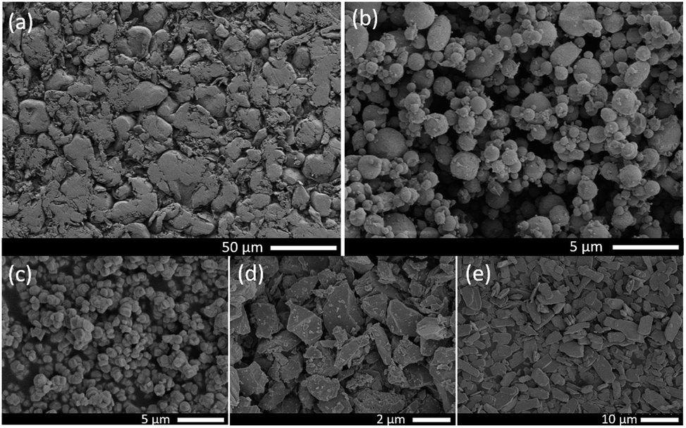 | ||
| Fig. 1 The initial microstructures of the raw materials: (a) PTFE; (b) Al; (c) Fe2O3; (d) MnO2; (e) MoO3. | ||
2.2 Specimens preparation
The theoretical chemical equilibrium ratio of Al to Fe2O3, Al to MnO2 and Al to MoO3 were 39.6 vol%/60.4 vol%, 43.4 vol%/56.6 vol% and 39.4 vol%/60.6 vol%, respectively. For the convenience of contrast and analysis, the volume fraction of Al to three types of oxides were all set to 40%/60%. Considering that when the PTFE content is too low, the material exhibits brittleness and fails at very low strain, which does not possess research and practical value, the volume fraction of PTFE added in the thermite system is 60% and 75% respectively. Table 1 tabulates the formulation of experimental specimens, along with the corresponding theoretical maximum density (TMD).| Type | Volume fraction (vol%) | TMD (g cm−3) | ||||
|---|---|---|---|---|---|---|
| Al | Fe2O3 | MnO2 | MoO3 | PTFE | ||
| A | 8 | 12 | — | — | 80 | 2.60 |
| B | 8 | — | 12 | — | 80 | 2.58 |
| C | 8 | — | — | 12 | 80 | 2.54 |
| D | 16 | 24 | — | — | 60 | 3.01 |
| E | 16 | — | 24 | — | 60 | 2.95 |
| F | 16 | — | — | 24 | 60 | 2.88 |
The preparation process was based on Nielson's patent, which included mixing, cold isostatic pressing and vacuum sintering.26 The raw materials were stirred mechanically for 20 min in an ethanol solution and dried for 48 h at 60 °C in a vacuum oven. Then the dried powder was cold pressed by FLS30T hydraulic press under a compressive pressure of 300 MPa to obtain cylindrical specimens with size of Φ10 mm × 10 mm. Finally, the pressed specimens were sintered in a vacuum oven at 360 °C for 4 h with a heating rate of 90 °C h−1 and a cooling rate of 50 °C h−1. The temperature change in sintering process is limned in Fig. 2.
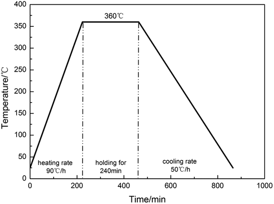 | ||
| Fig. 2 The temperature change in sintering process. | ||
2.3 Experimental procedures
Quasi-static compression tests were carried out by a CMT5105 electrohydraulic universal testing machine (MTS industry system Co. Ltd., Shenzhen, Guangdong, China) with a loading capacity of 100 kN. The load speed was set to 6 mm min−1 corresponding to a nominal strain rate of 0.01 s−1. Ambient temperature was 23 °C. In order to alleviate the influence of friction, all contact surfaces of the specimens were lubricated with petroleum jelly prior to the quasi-static compression tests. Triplicate experiments were carried out for each type of specimens. In total, eighteen specimens—three for each of the six types of specimens—were fabricated for testing to examine the consistency and reliability of the experimental results. To observe the reaction phenomenon more clearly and accurately, time sequences of the quasi-static compression tests were recorded by a digital high-speed camera with the frame rate of 20![[thin space (1/6-em)]](https://www.rsc.org/images/entities/char_2009.gif) 000 frames per s. To investigate the relation between the interior microstructures and the mechanical behavior of the materials, SEM was applied to characterize the interior microstructures of the materials.
000 frames per s. To investigate the relation between the interior microstructures and the mechanical behavior of the materials, SEM was applied to characterize the interior microstructures of the materials.
The engineering stress and engineering strain were calculated on the basis of the data measured directly from the universal testing machine. By supposing the volume of specimen remains constant when compressed, the true stress and true strain could be calculated by following equations:
 | (1) |
3 Results and discussion
3.1 Mechanical behavior under quasi-static compression
The true stress–strain curves of six types of fluorine-containing thermite are shown in Fig. 3, and the corresponding mechanical property parameters are listed in Table 2. It can be found that the six types of fluorinated thermite have experienced three stages of elastic deformation, plastic deformation and failure, and represented strain hardening phenomenon in the plastic deformation stage. However, there were significant differences in mechanical properties among the six types of fluorinated thermite. For comparison, the data in Table 2 are depicted in the form of column diagram, as shown in Fig. 4. PTFE/Al/Fe2O3 (type A and D) always had the highest yield strength and strain hardening modulus regardless of PTFE content. PTFE/Al/MnO2 (type B and E) exhibited the lowest yield strength and strain hardening modulus, but the highest compressive strength and toughness (the area under the stress–strain curve), indicating that it could absorb the most energy during compression. With the increase of PTFE content, the strength of three types of fluorine-containing thermite improved. This is because PTFE matrix was the main stress component of specimens in the compression process. Increasing PTFE content could make Al and oxide particles more uniformly distributed in the PTFE matrix. The bonding between the matrix and the reinforcing particles was closer, bringing about the strength of specimens enhanced accordingly.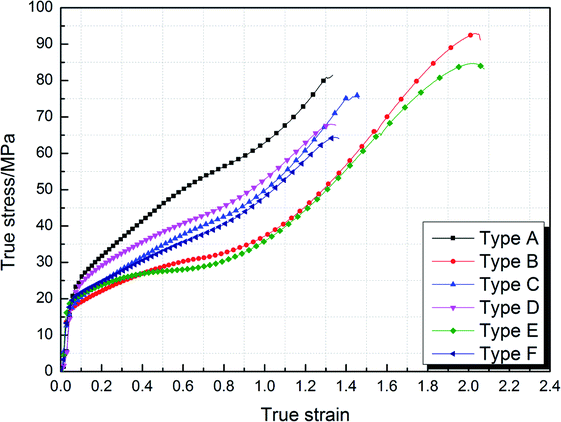 | ||
| Fig. 3 The true stress–strain curves of six types of experimental specimens under quasi-static compression. | ||
| Type | Yield strength/MPa | Hardening modulus/MPa | Compressive strength/MPa | Failure strain | Toughness/MJ m−3 |
|---|---|---|---|---|---|
| A | 23.53 | 45.34 | 80.93 | 1.33 | 67.42 |
| B | 16.86 | 36.69 | 92.95 | 2.05 | 96.80 |
| C | 17.42 | 40.89 | 75.91 | 1.46 | 62.79 |
| D | 22.67 | 35.15 | 68.00 | 1.35 | 58.04 |
| E | 18.93 | 32.64 | 84.69 | 2.07 | 94.61 |
| F | 19.81 | 34.63 | 64.39 | 1.36 | 53.19 |
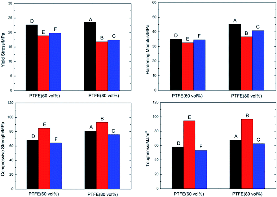 | ||
| Fig. 4 Comparison of mechanical properties parameters of six types of fluorine-containing thermite. | ||
Under the axial loading of universal testing machine, violent reaction happened to type A, B and C specimens, instead, type D, E and F specimens was compressed gradually and finally failed without reaction. Fig. 5 shows the deformation process and failure morphology of type D, E and F specimens under quasi-static compression. It can be observed that the three types of specimens had similar deformation process, but the final failure morphology were different. For the type D specimen, not only 45° shear cracks were formed in the specimen, but also mode I opening cracks were generated under the function of circumferential tensile stress. For the type E specimen, during the whole loading process, no obvious decrease of force value recorded by universal testing machine was observed. The universal testing machine carried on loading until reaching the set maximum load 80 kN (the criterion for universal testing machine to stop loading is that the load drops by 5% per second). The specimen did not show macroscopic crack, but was compressed into a round cake with a thickness of 1–1.5 mm, indicating that type E specimen had excellent ductility. It can be also confirmed from its mechanical curve that its failure strain reached 2.07. For the type F specimen, there was no distinct circumferential opening crack during the loading process, only 45° shear cracks appeared. Different from the type D and type E specimens, the failure surface of type F specimen exhibited very rough and slightly warped after the loading.
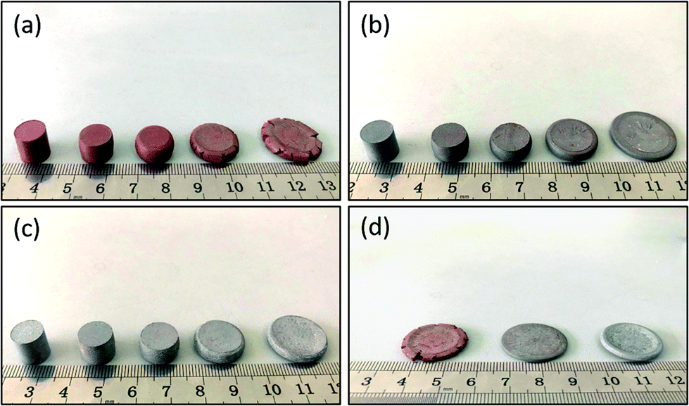 | ||
| Fig. 5 Comparison of deformation process and failure morphology of type D, E and F specimens under quasi-static compression: (a) type D; (b) type E; (c) type F; (d) failure morphology. | ||
3.2 Fractography analysis
Before the tests, the initial microstructures of type D, E and F specimens were characterized by SEM, as shown in Fig. 6. It can be found that Al, Fe2O3, MnO2 and MoO3 are uniformly distributed in PTFE matrix, indicating that initial powders were homogeneously mixed through the preparation process outlined in the paper.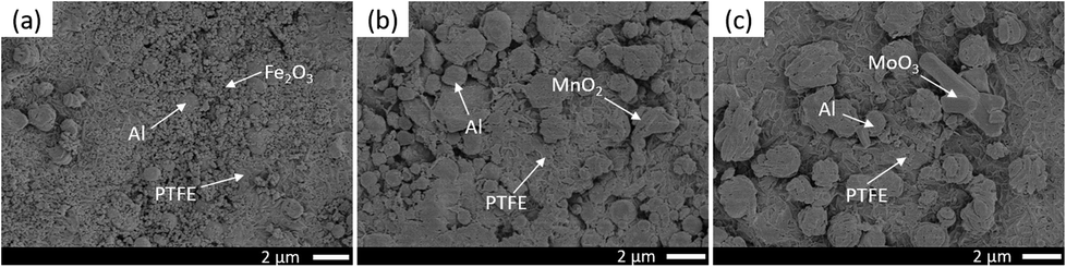 | ||
| Fig. 6 The initial microstructures of type D, E and F before compression: (a) type D; (b) type E; (c) type F. | ||
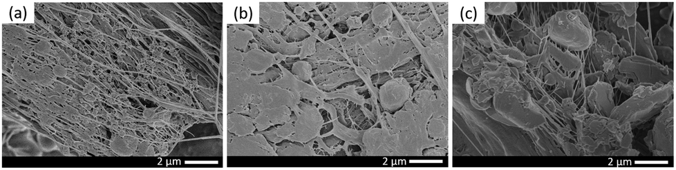
In order to explore the relationship between failure mode and microstructure of materials, SEM analysis was carried out on the hoop sections and compression failure surfaces of type D, E and F specimens after compression, as shown in Fig. 7 and 8 respectively. For the convenience of observation and comparison, the internal microstructures of three specimens at different magnifications were photographed by SEM. For the type D specimen, there were obvious opening cracks in the circumferential direction, and fractures were uneven. As can be seen from the crack section (Fig. 7d), under the effect of hoop tensile stress, Al and Fe2O3 particles were pulled out of the PTFE matrix and covered on the crack surface loosely. No orientation was found in the formed PTFE fibers, or PTFE fibers have been torn after forming orientation. For the type E specimen although no macroscopic cracks were observed on the specimen failure surface, the SEM image shows that there were still many tiny cracks on the circumferential surface. Obviously oriented PTFE fibers can be seen when cracks were observed at a larger magnification (Fig. 7e). The formation of these fibers could consume part of the energy absorbed when specimens were compressed, besides, the oriented fibers were capable of transferring the applied load and hindering the further crack extension. Therefore, the type E specimen had better ductility, and no macro-cracks were formed in its circumferential direction under the action of oriented PTFE filaments. For the type F specimen, it can be found from its SEM image that the surface was relatively rough, and the morphology was between that of type D and type E. A large number of filler particles were pulled out and covered on the surface, and PTFE fibers were formed at the same time, but the orientation of PTFE fibers were irregular, resulting in the ductility of type F specimen inferior to that of type E specimen.
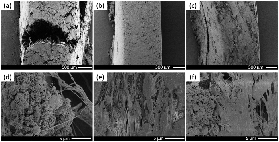 | ||
| Fig. 7 Microstructures of hoop sections of type D, E and F specimens: (a) and (d) type D; (b) and (e) type E; (c) and (f) type F. | ||
 | ||
| Fig. 8 Microstructures of compression failure surfaces of type D, E and F specimens: (a) type D; (b) type E; (c) type F. | ||
Fig. 8 shows the microstructures of compression failure surface of three types of fluorine-containing thermite specimens. The type D specimen had overt orientation along the radial direction, and the Al and Fe2O3 particles were compressed and deformed; while in the type E specimen, a small amount of filler particles were extruded, accompanied by a small amount of PTFE fibers formed, and most of PTFE was compacted and flattened with good integrity. In the type F specimen, massive Al particles and MoO3 were extruded, and the PTFE fibers formed were disorderly oriented, leading to that the coating effect on the filler particles was basically lost.
3.3 Reaction phenomenon under quasi-static compression
Type A, B and C specimens experienced a severe exothermic reaction under quasi-static compression, while no reaction occurred for type D, E and F specimens. The reaction process of type A, B and C specimens recorded by high-speed camera are presented in Fig. 9. As can be seen, the reaction took place on the edge of the specimen. It extinguished soon after the ignition and could not be stably propagated in the specimen, for example, the ignition of type A specimen lasted only about 1.2 ms. As the indenter of the universal testing machine continued to press down, the specimens would generate multiple ignitions, but none of them was capable of motivating the complete reaction of the specimens. After the part reaction of the specimens, a black product (carbon black) remained at the crack notch.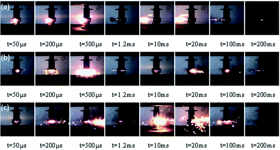 | ||
| Fig. 9 Reaction phenomena of type A, B and C specimens under quasi-static compression: (a) type A; (b) type B; (c) type C. | ||
To understand the reaction phenomenon under quasi-static compression and illuminate the chemical reaction mechanism of fluorine-containing thermite, the solid residuals after reaction were collected and characterized by X-ray diffraction. The XRD pattern of type A, B and C specimens before and after quasi-static compression are shown in Fig. 10. The results bespeaks that in addition to the original materials components, AlF3 was also found in the solid residuals after reaction for type A and C specimens. It can be inferred that Al reacted with PTFE, as shown in reaction eqn (2):
| 4Al + 3(–C2F4–) → 4AlF3 + 6C | (2) |
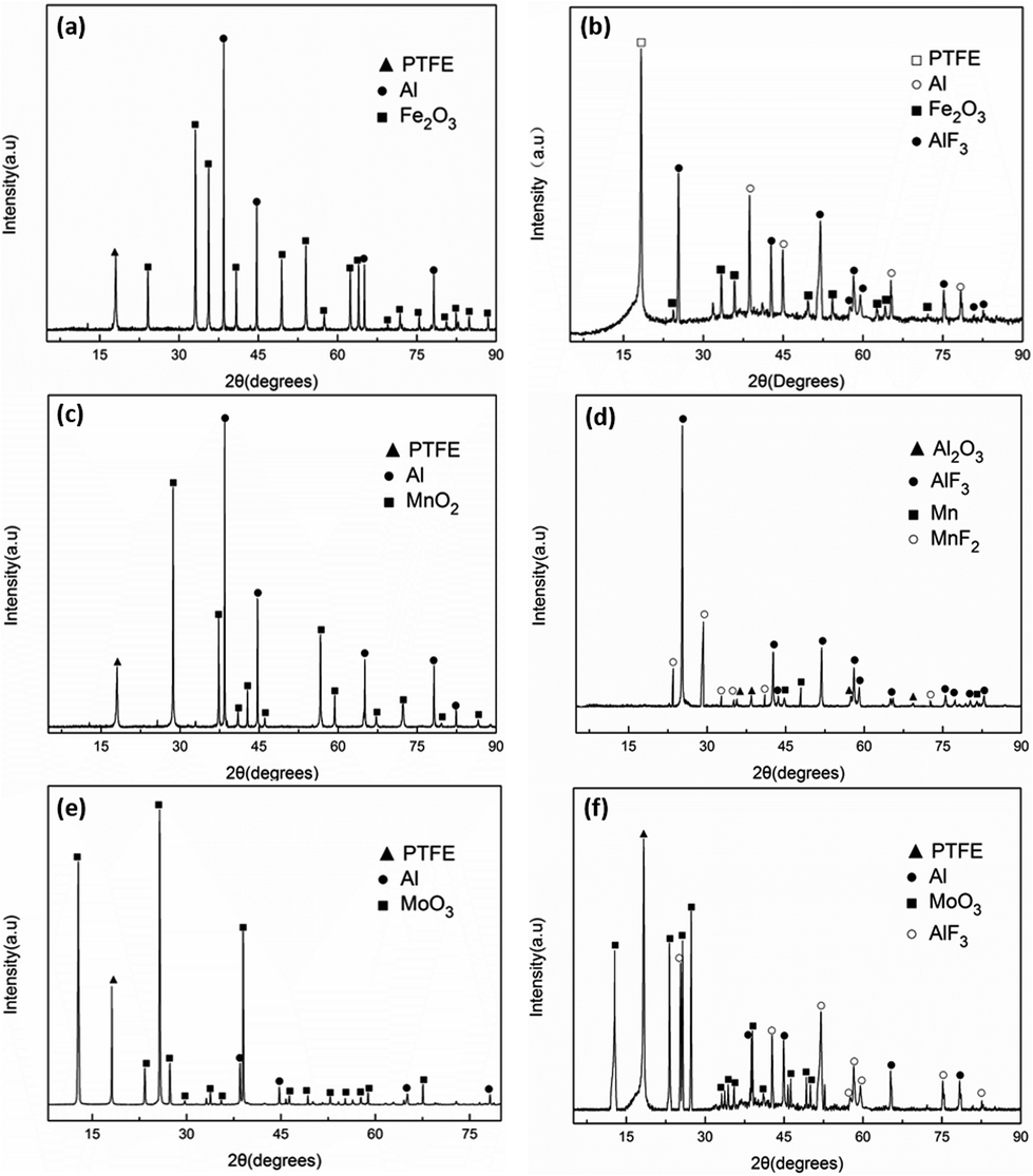 | ||
| Fig. 10 The XRD pattern of type A, B and C specimens: (a) type A specimen before compression; (b) type A specimen after compression; (c) type B specimen before compression; (d) type B specimen after compression; (e) type C specimen before compression; (f) type C specimen after compression. | ||
Although there was explosion reaction, the reaction did not turn to combustion. The reaction process was very short and could not maintain self-sustained. No suboxide or corresponding metal element was generated in the solid residuals, which means that the aluminothermal reaction between Fe2O3, MoO3 and Al was not triggered. In the fluorine-containing thermite reactive materials system, when the content of oxide was high, the reaction cannot occur in the case of quasi-static compression arising from the change of reaction pathway. When the amount of oxide was low, oxide was dispersed in the matrix and the contact between the oxide and Al was not sufficient, causing the specimen extinguished soon after ignition. The thermal conductivity of the PTFE matrix is poor. Before the heat generated by the reaction between Al and PTFE was transferred to the surrounding reactants, the heat has been dissipated. Besides, the activation energy of the reaction between Al and oxide is higher, the energy input by quasi-static compression was not enough to excite the reaction between Al and Fe2O3 or MoO3.
Different from the type A and type C specimens, it can be found that Mn and MnF2 were formed in the products of type B specimen. The thermite reaction between Al and MnO2 was induced. Because type B specimen possessed excellent ductility and absorbed the most energy during compression, the energy could stimulate the thermite reaction as well as the reaction of Al and PTFE. Zhang et al.27 investigated the thermal decomposition and thermal reaction process of PTFE/Al/MnO2 fluorinated thermite. Experimental results indicate that PTFE behaved as both oxidizer and reducer in PTFE/Al/MnO2 fluorinated thermite. MnO2 could react with PTFE at about 600 °C, which was close to the reaction temperature of Al and PTFE. Therefore, apart from eqn (2), the chemical reaction mechanism of type B specimen shall also include the following processes:
| 4Al + 3MnO2 → 3Mn + 2Al2O3 | (3) |
| 2MnO2 + (–C2F4–) → 2MnF2 + 2CO2(g) | (4) |
4 Conclusions
In this paper, PTFE/Al/Fe2O3, PTFE/Al/MnO2 and PTFE/Al/MoO3, solid fluorine-containing thermite with different PTFE content, were successfully fabricated by referring to the traditional thermite and adding PTFE as a binder or matrix. Quasi-static compression tests were performed to investigate the mechanical and reactive behavior of fluorine-containing thermite. SEM and XRD were employed to analyze and characterize the energetic composites and reaction residuals. The conclusions can be drawn as follows:(1) Under quasi-static compression, six types of fluorine-containing thermite took on different mechanical behavior. PTFE/Al/MnO2 exhibited the lowest yield strength and strain hardening modulus, but the highest compressive strength and toughness. With the increase of PTFE content, the strength of fluorine-containing thermite improved.
(2) The formation of PTFE fibers could consume part of the energy absorbed during compression and hinder the further crack extension. Ranking according to the function of PTFE fibers in the compression process, the descending order is PTFE/Al/MnO2, PTFE/Al/MoO3 and PTFE/Al/Fe2O3.
(3) No reaction occurred when PTFE content was 60 vol%, while fluorine-containing thermite with PTFE content of 80 vol% experienced a severe exothermic reaction under quasi-static compression. The ignition of PTFE/Al/MoO3 and PTFE/Al/Fe2O3 actually attributed to the reaction of Al and PTFE, and the reaction between Al and Fe2O3 or MoO3 was not excited duo to the insufficient input energy. The thermite reaction between Al and MnO2 as well as the reaction of MnO2 and PTFE were induced because PTFE/Al/MnO2 possessed excellent ductility and absorbed the most energy during compression, accompanied with the productions of Mn and MnF2.
Conflicts of interest
The authors declare that there is no conflict of interest regarding the publication of this paper.Acknowledgements
The financial support from the National Natural Science Foundation of China (General Program. Grant No. 51673213) and National Science Fund for Distinguished Young Scholars (Grant No. 51803235) are gratefully acknowledged.Notes and references
- W. He, P. J. Liu and G. Q. He, et al., Highly Reactive Metastable Intermixed Composites (MICs): Preparation and Characterization, Adv. Mater., 2018, 30, 1706293 CrossRef PubMed.
- M. L. Pantoya, V. I. Levitas and J. J. Granier, et al., Effect of Bulk Density on Reaction Propagation in Nanothermites and Micron Thermites, J. Propul. Power, 2009, 25, 465 CrossRef CAS.
- J. Mei, R. D. Halldearn and P. Xiao, et al., Mechanisms of the aluminium-iron oxide thermite reaction, Scr. Mater., 1999, 41, 541–548 CrossRef CAS.
- D. Spitzer, M. Comet and C. Baras, et al., Energetic nanomaterials: opportunities for enhanced performances, J. Phys. Chem. Solids, 2010, 71, 100 CrossRef CAS.
- A. C. Fernandez-Pello, Micropower Generation Using Combustion: Issues and Approaches, Proc. Combust. Inst., 2002, 29, 883–899 CrossRef.
- C. Rossi, K. Zhang, D. Esteve and P. Alphonse, et al., Nanoenergetic Materials for MEMS: A Review, J. Microelectromech. Syst., 2007, 16, 919 CAS.
- N. H. Yen and L. Y. Wang, Reactive Metals in Explosives, Propellants, Explos., Pyrotech., 2012, 37, 256 CrossRef CAS.
- K. T. Sullivan, N. W. Piekiel and C. Wu, et al., Reactive sintering: an important component in the combustion of nanocomposite thermites, Combust. Flame, 2012, 159, 2–15 CrossRef CAS.
- J. X. Song, T. Guo and W. Ding, et al., Study on thermal behavior and kinetics of Al/MnO2 poly(vinylidene fluorine) energetic nanocomposite assembled by electrospray, RSC Adv., 2019, 9, 25266 RSC.
- K. T. Sullivan, J. D. Kuntz and A. E. Gash, Electrophoretic deposition and mechanistic studies of nano-Al/CuO thermites, J. Appl. Phys., 2012, 112, 024316 CrossRef.
- J. Y. Huang, X. Fang and S. Z. Wu, et al., Mechanical Response and Shear-Induced Initiation Properties of PTFE/Al/MoO3 Reactive Composites, Materials, 2018, 11, 1200 CrossRef.
- J. Mccollum, M. L. Pantoya and S. T. Iacono, Activating Aluminum Reactivity with Fluoropolymer Coatings for Improved Energetic Composite Combustion, ACS Appl. Mater. Interfaces, 2015, 7, 18742 CrossRef CAS.
- Y. Park, S. Seo and S. Jang, et al., Investigation of Shear Induced Exothermic Thermite Reaction in Al-Fe2O3 Epoxy Cast Composites, Combust. Sci. Technol., 2016, 188, 895–909 CrossRef CAS.
- J. Y. Lyu, S. W. Chen and W. He, et al., Fabrication of High-Performance Graphene Oxide Doped PVDF/CuO/Al Nanocomposites via Electrospinning, Chem. Eng. J., 2019, 268, 129–137 CrossRef.
- W. He, Z. H. Li and S. W. Chen, et al., Energetic Metastable n-Al@PVDF/EMOF Composite Nanofibers with Improved Combustion Performances, Chem. Eng. J., 2019, 41, 123146 Search PubMed.
- M. I. Alymov, S. G. Vadchenko and I. S. Gordopolova, et al., Effect of Mechanical Activation on Thermally and Shock Wave Initiated Reactions of Refractory Metals with Teflon, Inorg. Mater., 2018, 54, 1175–1182 CrossRef CAS.
- Y. Zhang, Y. Yan and Y. Wang, et al., Enhanced Energetic Performances Based on Integration with the Al/PTFE Nanolaminates, Nanoscale Res. Lett., 2018, 13, 206 CrossRef PubMed.
- W. J. Ye, T. Wang and Y. H. Yu, Research Progress of Fluoropolymer-Matrix Energetic Reactive Materials, Aerosp. Mater. Technol., 2012, 42, 19–23 CAS.
- B. Feng, X. Fang, Y. C. Li, H. X. Wang, Y. M. Mao and S. Z. Wu, An initiation phenomenon of Al-PTFE under quasi-static compression, Chem. Phys. Lett., 2015, 637, 38–41 CrossRef CAS.
- B. Feng, Y. C. Li, S. Z. Wu, H. X. Wang, Z. M. Tao and X. Fang, A crack-induced initiation mechanism of Al-PTFE under quasi-static compression and the investigation of influencing factors, Mater. Des., 2016, 108, 411–417 CrossRef CAS.
- J. X. Wu, X. Fang and Z. R. Gao, et al., Investigation on Mechanical Properties and Reaction Characteristics of Al-PTFE Composites with Different Al Particle Size, Adv. Mater. Sci. Eng., 2018, 2018, 1–10 Search PubMed.
- L. L. Ding, J. Y. Zhou and W. H. Tang, et al., Impact Energy Release Characteristics of PTFE/Al/CuO Reactive Materials Measured by a New Energy Release Testing Device, Polymers, 2019, 11, 149 CrossRef PubMed.
- D. T. Osborne and M. L. Pantoya, Effect of Al particle size on the thermal degradation of Al/Teflon mixtures, Combust. Sci. Technol., 2007, 179, 1467–1480 CrossRef CAS.
- H. X. Wang, X. Fang and B. Feng, et al., Influence of Temperature on the Mechanical Properties and Reactive Behavior of Al-PTFE under Quasi-Static Compression, Polymers, 2018, 10, 56 CrossRef PubMed.
- C. Ge, Y. Dong and W. Maimaitituersun, et al., Experimental Study on Impact-induced Initiation Thresholds of Polytetrafluoroethylene/Aluminum Composite, Propellants, Explos., Pyrotech., 2017, 42, 1–10 CrossRef.
- D. B. Nielson, R. M. Truitt and B. N. Ashcroft, Reactive Material Enhanced Projectiles and Related Methods, US Pat., 2008/0035007 A1, 14 February 2008.
- J. Zhang, J. Y. Huang and X. Fang, et al., Thermal Decomposition and Thermal Reaction Process of PTFE/Al/MnO2 Fluorinated Thermite, Materials, 2018, 11, 2451 CrossRef CAS PubMed.
| This journal is © The Royal Society of Chemistry 2020 |