 Open Access Article
Reduced graphene oxide/TiO2(B) nanocomposite-modified separator as an efficient inhibitor of polysulfide shuttling in Li–S batteries†
Peng Chen abc,
Zexi Wanga,
Bingyu Zhanga,
Heng Liua,
Wanqiang Liu
 *abc,
Jianxun Zhao*ab,
Zhihua Ma
 abc,
Wenyue Dong
 abc and
Zhongmin Suac
aSchool of Materials Science and Engineering, Changchun University of Science and Technology, Changchun 130022, China. E-mail: wqliu1979@126.com
bEngineering Research Center of Optoelectronic Functional Materials, Ministry of Education, China
cJilin Provincial Science and Technology Innovation Center of Optical Materials and Chemistry, China
First published on 28th January 2020
Abstract
The shutting effect in lithium–sulfur (Li–S) batteries hinders their widespread application, which can be restrained effectively by a modified separator. In this work, a composite of reduced graphene oxide and beta-phase TiO2 nanoparticles (RGO/TiO2(B)) is designed as a separator modification material for improving the electrochemical behavior of Li–S batteries. The TiO2(B) nanoparticles are in situ prepared and tightly adhere to the RGO layer. A series of examinations demonstrated that the RGO/TiO2(B)-coated separator efficiently inhibits the polysulfide shuttling phenomenon by the cooperative effect of physical adsorption and chemical binding. Specifically, as modified separators, a comparison between TiO2(B) and anatase TiO2(A) each composited with RGO has been conducted. The TiO2(B) sample not only exhibits a superior blocking character of migrating polysulfides, but also enhances battery electrochemical kinetics by fast Li ion diffusion.
1. Introduction
To meet the continuously growing demand for energy storage systems, the lithium–sulfur (Li–S) battery as a promising candidate receives significant attention because of its high theoretical capacity (1675 mA h g−1) and excellent theoretical energy density (2600 W h kg−1).1–4 The advantages of low cost, readily available material and environmental friendliness provide the foundation for Li–S batteries' more widespread application.5–10 But, there are some issues with Li–S batteries that badly hamper the development of commercial utilization, such as the volumetric expansion of cathode (80%), the poor sulfur conductivity and polysulfide shuttling.10–14 These burning issues consequently lead to low sulfur utilization, negative coulombic efficiency and inferior cycling stability.15,16 In order to solve the above problems, a series of strategies have been carried out by researchers including using designed sulfur scaffolds,17,18 anode protections,19,20 and electrolyte additives,21–23 inserting interlayers24–26 and the modification of separators.27–30Among these strategies, a modified separator limits polysulfide shuttling and enhances sulfur utilization, which is a positive and economical method to enhance Li–S batteries' electrochemical performance.31,32 To date, many materials including carbon, polymers, metal oxides and metal sulfides have been used to modify the separators.33–35 The modifying materials form an adsorption functional layer to efficiently entrap polysulfides. Ti-based materials are considered as promising modifying materials due to their polarized surface, good chemical properties and thermal stability. For example, Shao et al. reported that the “shuttle effect” in Li–S batteries was suppressed efficiently by a nano-TiO2/carbon-modified separator, in which the nano-TiO2 trapped polysulfides by a chemical and physical synergetic effect.36 Li et al. designed an interlayer using mesoporous TiO2-carbon nanotubes materials in Li–S batteries to suppress the shuttling of polysulfide.37 Xu et al. reported multifunctional TiN/C65 coating separators used in Li–S batteries, which deliver an initial specific capacity of 935 mA h g−1 at 0.5C.38 However, in contrast to anatase and rutile TiO2, few studies about beta-phase TiO2 (TiO2(B)) as a modifying material for separators in Li–S batteries have been reported. As previously reported, Chen et al. demonstrated that sulfur hosts were fabricated using TiO2(B) nanotubes compounded with carbon nanotubes to improve the capacity retention of Li–S batteries successfully.39 The results indicate that TiO2(B) enables polysulfides to be immobilized owing to the occurrence of chemical bonding. Inspired by these results, we presented a multi-functional separator with reduced graphene oxide/TiO2(B) (RGO/TiO2(B)) nanoarchitectures coating a PP separator for the suppression of polysulfide shuttling. In addition, RGO has many oxygen-containing functional groups, which also can bind polysulfides and inhibit the “shuttle effect” in Li–S batteries.40,41
In this work, RGO/TiO2(B) nanoarchitectures were successfully prepared using a facile approach, and exhibited excellent physical and chemical properties when used to modify the separators of Li–S batteries. The TiO2(B) nanoparticles were uniformly distributed on the RGO surface. The polarity of TiO2(B) can help to trap polysulfides, and the interaction between TiO2(B) and polysulfides was characterized by X-ray photoelectron spectroscopy (XPS). Compared to batteries with RGO and anatase TiO2 nanoparticles (RGO/TiO2(A))-modified separators, the diffusion of Li ions in RGO/TiO2(B) batteries was significantly improved. The Li–S battery with RGO/TiO2(B)-modified separator exhibited a superior initial discharge capacity of 1097.5 mA h g−1 at a current density of 0.2C, which was obviously higher than that of 873.6 mA h g−1, 765.2 mA h g−1 and 525.3 mA h g−1 in these batteries with RGO/TiO2(A)-modified separator, RGO-modified separator and pristine separator, respectively.
2. Experimental
2.1 Material preparation
The RGO/TiO2(B) nanoarchitectures were synthesized via a hydrothermal route.42,43 Graphene oxide (GO) nanosheets were prepared by using a modified Hummers' method.44 20 mg GO nanosheets was dispersed into 40 mL deionized ice water. 0.8 mL TiCl4 was added dropwise slowly. 5 mL ammonium hydroxide was added to the solution to form a white floc. After adding 60 mL deionized water, vigorous stirring was continued for 5 min. And then, 10 mL hydrogen peroxide (H2O2; concentration: 60%) was added and stirred for 10 min. The colour of the solution turned yellow. Then was added 0.5 g glycolic acid (C2H4O3) with stirring for 5 min. The autoclave was kept at 80 °C for 390 min, and cooled to room temperature naturally. Droplets of H2SO4 were added to adjust the pH value to 1 with stirring for 5 min. The solution was put into a 50 mL reaction still and kept at 160 °C for 50 min. The solution was cooled to 25 °C naturally. The product was purified using a washing process with deionized water and alcohol. RGO/TiO2(B) was successfully synthesized.2.2 The preparation of functional separators
RGO/TiO2(B) was used to modify a 2400 Cegard film using the vacuum filtration method. Solutions with RGO/TiO2(B) were shaken by ultrasound for 2 h to obtain homogeneous suspensions. Then the above mixed solutions were poured into a vacuum filter to remove alcohol for modified separator fabrication. The modified separators were dried in a vacuum drying oven at 60 °C for 12 h.2.3 Preparation of the pure sulfur cathode
The cathode was fabricated by grinding sulfur powder, acetylene black and polyvinylidene fluoride (7![[thin space (1/6-em)]](https://www.rsc.org/images/entities/char_2009.gif) :
:![[thin space (1/6-em)]](https://www.rsc.org/images/entities/char_2009.gif) 3
3![[thin space (1/6-em)]](https://www.rsc.org/images/entities/char_2009.gif) :
:![[thin space (1/6-em)]](https://www.rsc.org/images/entities/char_2009.gif) 1 wt%) in N-methyl-2-pyrrolidone solution. The amount of sulfur in the composite was 63%. After that, the homogeneous slurry was coated on aluminum foil with carbon coating, and was dried in a vacuum oven at 60 °C for 12 h. The cathodes were cut into disks, with a pure sulfur loading of about 3 mg cm−2.
1 wt%) in N-methyl-2-pyrrolidone solution. The amount of sulfur in the composite was 63%. After that, the homogeneous slurry was coated on aluminum foil with carbon coating, and was dried in a vacuum oven at 60 °C for 12 h. The cathodes were cut into disks, with a pure sulfur loading of about 3 mg cm−2.
2.4 Cell assembly
In an argon-filled glove box, CR2025-type devices were fabricated with RGO/TiO2(B)-modified separator, the cathode as described above and pure lithium anode. The electrode to sulfur ratio (E/S) was kept at 30 μL mg−1. Lithium bistrifluoromethanesulfonylimide (LiTFSI) (1.0 M) and lithium nitrate (0.4 M) were dissolved in 1,3-dioxolane and 1,2-dimethoxyethane (1![[thin space (1/6-em)]](https://www.rsc.org/images/entities/char_2009.gif) :
:![[thin space (1/6-em)]](https://www.rsc.org/images/entities/char_2009.gif) 1 v/v) and used as the electrolyte.
1 v/v) and used as the electrolyte.
3. Results and discussion
3.1 Structures and morphologies
Fig. 1 illustrates a comparison of Li–S batteries with a pristine separator and the RGO/TiO2(B)-modified separator as well as the preparation process of the RGO/TiO2(B) nanoarchitectures. There is an obvious “shuttle effect” of polysulfides in the battery with the pristine separator in Fig. 1a. In contrast, the RGO/TiO2(B)-coated separator blocks the “shuttle effect” by anchoring the polysulfides efficiently, as shown in Fig. 1b. In this work, TiO2(B) provides strong chemical adsorption of polysulfides and channels for the diffusion of Li ions. On the other hand, the RGO layers trap the polysulfides not only by physical adsorption owing to the two-dimensional network structure, but also by chemical binding owing to the oxygen-containing functional groups.45,46 As shown in Fig. 1c, the RGO/TiO2(B) nanoarchitectures are fabricated by an in situ hydrothermal route. TiO2(B) disperses on the RGO layers uniformly and exhibits a stable interaction with RGO layers.43 The modified separators are prepared by deposition of RGO/TiO2(B) on pristine film with vacuum filtration.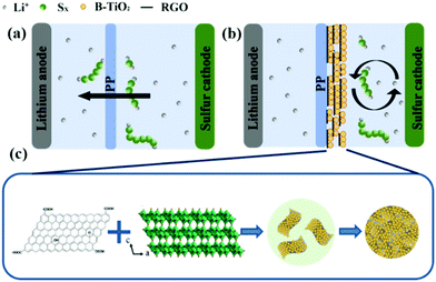 | ||
| Fig. 1 Schematic diagrams of the polysulfide shuttle effect in Li–S batteries using (a) a PP separator and (b) a RGO/TiO2(B)-modified separator. (c) Preparation of the RGO/TiO2(B) nanoarchitectures. | ||
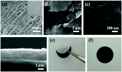
The morphologies of the pristine separator and RGO- and RGO/TiO2(B)-modified separators were investigated by SEM as shown in Fig. 2a–c. As shown in the SEM images, the modified material completely covers the pristine film and blocks the pores on the film, which can directly inhibit polysulfide diffusion. The TiO2(B) nanoparticles are dispersed on the RGO layer uniformly, which means that the TiO2(B) nanoparticles and the RGO layers are well combined. The EDAX results also prove that TiO2(B) adheres on the surface of RGO (Fig. S1†). The SEM image of a cross-section (Fig. 2d) of the RGO/TiO2(B)-modified separator indicates that the modified layer combines well with the pristine film, and the optimized thickness is about 5 μm. For comparison, a photograph of a RGO/TiO2(B)-modified separator with thicker coating is shown in Fig. S2.† The thick coating layer leads to cracking and peeling off from the PP separator and further influences the separator quality. In Fig. 2e and f, the folded and covered RGO/TiO2(B)-modified separators suggest that the modified separator exhibits excellent flexibility and mechanical strength.47
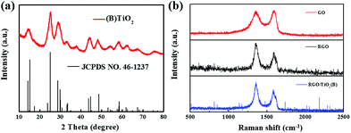
In order to investigate the structural characteristics of TiO2(B) and RGO/TiO2(B), the products were examined by XRD and Raman spectroscopy. The XRD pattern (Fig. 3a) shows diffraction peaks with weak intensities and broad half-peak width, illustrating that the particle size of TiO2(B) phase is small owing to the disorder eliciting lattice strains.48 The Raman spectra of GO, RGO and RGO/TiO2(B) are shown in Fig. 3b, in which there are two prominent peaks corresponding D band and G band, respectively. The D band is related to the disorder in the graphitic lattice, and the G band is assigned to the ordered graphitic regions with the stretching motion of carbon atoms in the plane. The intensity ratio of ID/IG is usually used to deduce the degree of disorder of the sp2 domains. By calculation, the ID/IG values of RGO and RGO/TiO2(B) are 1.38 and 1.56. This result suggests that the TiO2(B) nanoparticles anchor on the RGO sheet and reduce the oxidized carbon atoms or point defects.49 Moreover, the content of TiO2(B) nanoparticles is 48.5 wt% in the RGO/TiO2(B) compound (Fig. S3†).
3.2 Electrochemical performance
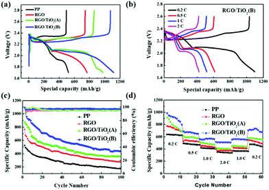
The initial discharge–charge profiles of all batteries at 0.2C are shown in Fig. 4a and the cycling of 1st, 10th, 20th and 100th cycle for all batteries are shown in Fig. S4.† All the batteries exhibit the typical two-plateau discharge curve and one charge plateau corresponding to the redox reaction, and the charge and discharge plateau voltage difference is the polarization potential (ΔE). The polarization potentials of the batteries with the pristine and RGO-coated separators are higher than that with RGO/TiO2(B) (ΔEpp > ΔERGO > ΔERGO/TiO2(A) > ΔERGO/TiO2(B)), and the phenomenon is consistent with that of the CV curves. The discharge–charge performances at different rates from 0.2C to 2C for RGO/TiO2(B) separator batteries (Fig. 4b), RGO separator batteries and RGO/TiO2(A) separator batteries (Fig. S5†) are illustrated. The battery with the RGO/TiO2(B)-coated separator has the smallest polarization potential and the best discharge–charge plateau superposition, indicating a smaller electrochemical kinetic barrier and better stability than the other samples.50 The galvanostatic cycle ability measurement shows that the battery with RGO/TiO2(B) has better cycling ability than the others (Fig. 4c), revealing the effectiveness of RGO/TiO2(B) for polysulfide suppression in long-term cycling.51 The RGO/TiO2(B) separator battery delivers a high capacity of 1097.5 mA h g−1 for the initial specific discharge capacity, which remains at 454.0 mA h g−1 after 100 cycles at a rate of 0.2C. The coulombic efficiencies of the batteries with different separators are all higher than 95%. Comparing with battery performance reported in some recent literature, the battery performance in our work achieves a mean level.51–54 The rate capabilities of the RGO/TiO2(B) separator battery are examined at 0.2C, 0.5C, 1C and 2C (Fig. 4d), which are 997.8, 689.1, 565.6 and 518.0 mA h g−1, respectively. It is worth mentioning that when the current density returned to 0.2C, a capacity of 707.6 mA h g−1 is reached. Compared with other samples, the capacity values at various rates and capacity reversibility of the RGO/TiO2(B) sample are all superior, proving that the RGO/TiO2(B) coating still effectively suppresses the shuttle effect of polysulfides even at the condition of high density of ions. All the results above collectively demonstrate that the RGO/TiO2(B)-modified separator effectively enhances the capacity and cycling ability, owing to the adsorption of polysulfides and promotion of the electrochemical reaction.3.3 Electrochemical process analysis
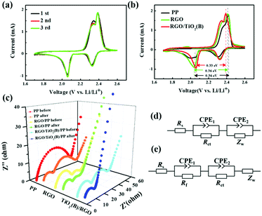
The cyclic voltammetry (CV) plots for batteries with the PP and RGO- and RGO/TiO2(B)-modified separators were measured. There are two reduction peaks for the cathode corresponding to the reduction process of pure sulfur to the intermediate polysulfides and then to Li2S2/Li2S. The oxidation peak for the anode is related to the conversion of Li2S/Li2S2 to polysulfides and sulfur. The initial three CV curves of RGO/TiO2(B) in Fig. 5a present no obvious shift or current change, which suggests high reversibility in the battery using the RGO/TiO2(B) modification. In order to compare the effects of the different modification coatings on the electrochemical reaction, the CV plots of the batteries with PP, RGO and RGO/TiO2(B) separators for the first cycle are collected in Fig. 5b. It is obvious that the reduction peaks for RGO/TiO2(B) are the most sharpened, suggesting that the sulfide distributes on RGO/TiO2(B) more homogeneously than in other samples. Furthermore, the battery with the RGO/TiO2(B) separator shows a lower ΔE than the RGO and PP samples, indicating that the RGO/TiO2(B) modification layer facilitates electrochemical reactions and reduces charge transfer resistance.55 The effect of modification on the electrochemical kinetics in the batteries was explored in detail by EIS measurements, as shown in Fig. 5c. The EIS spectra for the batteries before and after cycling are modeled using the equivalent circuits (Fig. 5d and e, respectively), where Rs is the contact resistance for the whole battery, Zw is the Warburg impedance corresponding to Li ion diffusion in solid state, while CPE represents double layer capacitance. After cycling, the EIS plots present two semicircles, in which the low-frequency one is associated with the charge transfer resistance (Rct) between the cathode and the electrolyte, and the high-frequency one is the interface contact resistance (Rf) for the lithium sulfide insulating layer in the surface of sulfur cathode. Before cycling, the semicircle at high frequency is also assigned to Rct, while the low-frequency one is related to Zw.56,57 It is clearly seen that Rct values of RGO and RGO/TiO2(B) both before and after cycling are smaller than those of the PP sample, because RGO and RGO/TiO2(B) provide additional pathways and continuous electrolyte channels for Li ion diffusion, owing to the superior conductive property and the wrinkled and folded construction. After cycling, the Rct value in the TiO2(B) battery is lowest, which is attributed to the strong binding ability of polysulfides benefiting Li ion migration. Moreover, the Rf values in the samples are similar, because of the solid Li2S2/Li2S formation. Thus, we can conclude that the RGO/TiO2(B)-coated separator enhanced the reaction kinetics for the Li–S batteries effectively.3.4 Mechanism of TiO2(B) chemisorption of polysulfides
In order to illustrate the chemical reaction, the surface properties of the modified separators in the Li–S batteries were examined using XPS. The binding energy peaks corresponding Ti 2s, Ti 2p, Ti 3s, Ti 3p, O 1s, C 1s, S 2s and S 2p are shown in Fig. 6a. The binding energy peaks of Ti 2p before and after cycling are contrasted in Fig. 6b. Both spectra show two predominant binding energy peaks at 459.6 and 469.6 eV indicating Ti 2p3/2 and Ti 2p1/2. A new peak at 461.6 eV appears after cycling, possibly suggesting the interaction between Ti and polysulfides. As shown in Fig. 6c, the spectrum of C 1s after cycling presents five peaks at 284.7, 285.2, 287.0, 288.8 and 289.9 eV corresponding to C–C/C![[double bond, length as m-dash]](https://www.rsc.org/images/entities/char_e001.gif) C, C–S, C
C, C–S, C![[double bond, length as m-dash]](https://www.rsc.org/images/entities/char_e001.gif) O, O–C
O, O–C![[double bond, length as m-dash]](https://www.rsc.org/images/entities/char_e001.gif) O and C–CO3, respectively.58,59 Fig. 6d shows a strong pair of peaks at binding energies of 168.4 and 169.5 eV assigned to S 2p1/2 and S 2p3/2 of O
O and C–CO3, respectively.58,59 Fig. 6d shows a strong pair of peaks at binding energies of 168.4 and 169.5 eV assigned to S 2p1/2 and S 2p3/2 of O![[double bond, length as m-dash]](https://www.rsc.org/images/entities/char_e001.gif) S
S![[double bond, length as m-dash]](https://www.rsc.org/images/entities/char_e001.gif) O, respectively.60 Another very weak couple of peaks at 163.0 and 161.5 eV can be assigned to the signals of a bridge sulfur of polysulfide species. Base on the results of the XPS analysis, we can conclude that polysulfides are well immobilized in the RGO/TiO2(B) composite via Ti–S and C–S bonds, resulting in the “shuttle effect” being well restrained.61
O, respectively.60 Another very weak couple of peaks at 163.0 and 161.5 eV can be assigned to the signals of a bridge sulfur of polysulfide species. Base on the results of the XPS analysis, we can conclude that polysulfides are well immobilized in the RGO/TiO2(B) composite via Ti–S and C–S bonds, resulting in the “shuttle effect” being well restrained.61
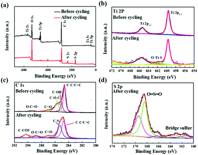 | ||
| Fig. 6 (a) XPS spectra of surface of RGO/TiO2(B) separator before and after 100 cycles. (b–d) High-resolution XPS survey scans of C 1s, Ti 2p, and S 2p. | ||
3.5 Comparison of TiO2(B)- and TiO2(A)-coated separators
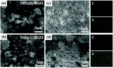
To further explore the ability to suppress the “shuttle effect”, we compared batteries with RGO/TiO2(B)-coated separator and RGO/TiO2(A)-coated separator. We analyzed the surface morphology using SEM and EDX mapping. SEM images of both sides of the separators and EDX mappings of the anode-facing surface after 200 cycles at 0.2C are all illustrated in Fig. 7a–d. Both the front-surface SEM images reveal polysulfide agglomerations (Fig. 7a and b). As shown in the reverse side SEM images and EDX mappings in Fig. 7c and d, the sulfur content in the RGO/TiO2(A)-coated separator is much higher than in the RGO/TiO2(B)-coated separator. The results prove directly that RGO/TiO2(B) can inhibit polysulfide shuttling more efficiently than RGO/TiO2(A).Fast Li ion diffusion facilitates the electrochemical reaction kinetics. We also investigated the Li ion diffusion in RGO/TiO2(B) and RGO/TiO2(A) separators for the Li–S batteries. The diffusion coefficients of Li ions were measured by CV and were calculated by the Randles–Sevcik equation:62,63
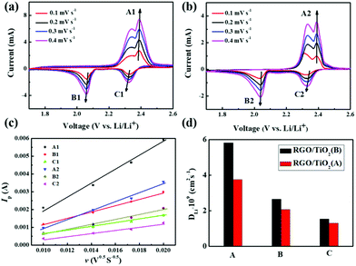
| Ip = 2.69 × 10⁵n1.5ADLi+0.5v0.5CLi+ = B × v0.5 | (1) |
In the CV curves, the oxidation peak was denoted as peak A, and the two reduction peaks were assigned as B and C, respectively. We obtained the CV curves at different scan rates as shown in Fig. 8a and b, and fitted the relationship between Ip and v0.5 in Fig. 8c. From the good linear fit, the corresponding DLi+ values can be calculated as shown in Fig. 8d and Table 1. The DLi+ values of all three peaks for the RGO/TiO2(B) sample are higher than those for the RGO/TiO2(A) sample, clearly demonstrating that the Li ion diffusion in the RGO/TiO2(B) battery was increased obviously. We speculate that the smaller nanoscale size of TiO2(B) with a short b-axis provides a more open channel along the [010] direction for improving the Li ionic conductivity. Thus, there is a faster electrochemical reaction dynamic in the batteries due to the presence of the polar TiO2(B), which also explains the results of the higher rate capability for the RGO/TiO2(B) sample.64
| DLi+ (A1) | DLi+ (A2) | DLi+ (B1) | DLi+ (B2) | DLi+ (C1) | DLi+ (C2) | |
|---|---|---|---|---|---|---|
| DLi+ (cm2 s−1) | 5.10 × 10⁻⁹ | 3.29 × 10⁻⁹ | 2.33 × 10⁻⁹ | 1.81 × 10⁻⁹ | 1.34 × 10⁻⁹ | 1.15 × 10⁻⁹ |
4. Conclusions
In this study, RGO/TiO2(B) composites were in situ synthesized as a modifying material on a PP separator for Li–S batteries using a hydrothermal method. The TiO2(B) nanoparticles disperse uniformly on the RGO layer and anchor on the RGO sheet tightly. The two-dimensional network structure and the oxygen-containing functional groups of RGO facilitate the physical adsorption and the chemical binding of polysulfides. Moreover, the polarity of TiO2(B) helps to enhance polysulfide anchoring via chemical interaction. Thus, with the use of the RGO/TiO2(B)-coated separator, the electrochemical performances of Li–S batteries, such as the specific capacity, cycling stability and rate discharge, are significantly improved. In addition, the RGO/TiO2(B) coating shows a higher Li ion diffusion coefficient and a better blocking effect of polysulfide migration than the RGO/TiO2(A) coating, which are consistent with the comparison of results of the battery performance. This study indicates that TiO2(B) is a promising material for modifying separators, which not only restrains the “shuttle effect” but also enhances the electrochemical kinetics for Li–S batteries.Conflicts of interest
The authors declare there is no conflicts of interest regarding the publication of this paper.Acknowledgements
This work was supported by the National Natural Science Foundation of China [51802026, 51803013], Nation Key R&D Program of China [2017YFE9128100], the Jilin Province Science and Technology Development Project [20180520178JH, 20190103023JH], the Department of Education of Jilin Province “13th Five-Year Plan” Project for Science and Technology [JJKH20181121KJ, JJKH20181118KJ], and the Changchun Planning Project of Science and Technology [17DY028].Notes and references
- P. G. Bruce, S. A. Freunberger, L. J. Hardwick and J. M. Tarascon, Nat. Mater., 2012, 11, 19–29 CrossRef CAS PubMed.
- J. Cao, C. Chen, Q. Zhao, N. Zhang, Q. Q. Lu, X. Y. Wang, Z. Q. Niu and J. Chen, Adv. Mater., 2016, 28, 9629–9636 CrossRef CAS PubMed.
- T. Chen, Z. W. Zhang, B. R. Cheng, R. P. Chen, Y. Hu, L. B. Ma, G. Y. Zhu, J. Liu and Z. Jin, J. Am. Chem. Soc., 2017, 139, 12710 CrossRef CAS PubMed.
- W. Chen, T. Y. Lei, C. Y. Wu, M. Deng, C. H. Gong, K. Hu, Y. C. Ma, L. P. Dai, W. Q. Lv, W. D. He, X. J. Liu, J. Xiong and C. L. Yan, Adv. Energy Mater., 2018, 8, 1702348 CrossRef.
- W. Chen, T. Y. Lei, W. Q. Lv, Y. Hu, Y. C. Yan, Y. Jiao, W. D. He, Z. H. Li, C. L. Yan and J. Xiong, Nat. Mater., 2018, 30, 1804084 Search PubMed.
- X. Fang, W. Weng, J. Ren and H. S. Peng, Adv. Mater., 2016, 28, 491–496 CrossRef CAS PubMed.
- Y. Q. Chen, H. Z. Zhang, W. B. Xu, X. F. Yang, Y. Yu, X. F. Li and H. M. Zhang, Adv. Funct. Mater., 2018, 28, 1704987 CrossRef.
- J. Conder, R. Bouchet, S. Trabesinger, C. Marino, L. Gubler and C. Villevieille, Nat. Energy, 2017, 2, 17069 CrossRef CAS.
- C. L. Dai, J. M. Lim, M. Q. Wang, L. Y. Hu, Y. M. Chen, Z. Y. Chen, H. Chen, S. J. Bao, B. L. Shen, Y. Li, G. Henkelman and M. W. Xu, Adv. Funct. Mater., 2018, 28, 1704443 CrossRef.
- Y. F. Dong, S. H. Zheng, J. Q. Qin, X. J. Zhao, H. D. Shi, X. H. Wang, J. Chen and Z. S. Wu, ACS Nano, 2018, 12, 2381–2388 CrossRef CAS PubMed.
- S. Chen, Y. Gao, Z. Yu, M. L. Gordin, J. X. Song and D. H. Wang, Nano Energy, 2017, 31, 418–423 CrossRef CAS.
- H. P. Li, L. C. Sun, Z. Wang, Y. G. Zhang, T. Z. Tan, G. K. Wang and Z. Bakenov, Nanomaterials, 2018, 8, 69–80 CrossRef PubMed.
- X. D. Huang, B. Sun, K. F. Li, S. Q. Chen and G. X. Wang, J. Mater. Chem. A, 2013, 1, 13484–13489 RSC.
- W. D. Zhou, H. Chen, Y. C. Yu, D. L. Wang, Z. M. Cui, F. J. DiSalvo and H. D. Abruna, ACS Nano, 2013, 7, 8801–8808 CrossRef CAS PubMed.
- S. H. Li, X. H. Xia, Y. D. Wang, X. L. Wang and J. P. Tu, J. Power Sources, 2017, 342, 224–230 CrossRef CAS.
- S. R. Chen, Y. Gao, Z. X. Yu, M. L. Gordin, J. X. Song and D. H. Wang, Nano Energy, 2017, 31, 418–423 CrossRef CAS.
- X. Hong, J. Jin, T. Wu, Y. Lu, S. Zhang, C. Chen and Z. Wen, J. Mater. Chem. A, 2017, 5, 14775 RSC.
- J. Wang, T. Wu, S. Zhang, S. Gu, J. Jin and Z. Wen, Chem. Eng. J., 2017, 334, 2356 CrossRef.
- Z. Wu, W. Wang, Y. Wang, C. Chen, K. Li, G. Zhao, C. Sun, W. Chen, L. Ni and G. Diao, Electrochim. Acta, 2017, 224, 527–533 CrossRef CAS.
- H.-K. Jing, L.-L. Kong, S. Liu, G.-R. Li and X.-P. Gao, J. Mater. Chem. A, 2015, 3, 12213 RSC.
- G. Ma, Z. Wen, M. Wu, C. Shen, Q. Wang, J. Jin and X. Wu, Chem. Commun., 2014, 50, 14209 RSC.
- H. L. Pan, K. S. Han, M. Vijayakumar, J. Xiao, R. G. Cao, J. Z. Chen, J. G. Zhang, K. T. Mueller, Y. Y. Shao and J. Liu, ACS Appl. Mater. Interfaces, 2017, 9, 4290–4295 CrossRef CAS PubMed.
- Y. L. Chen, N. Q. Liu, H. Y. Shao, W. K. Wang, M. Y. Gao, C. M. Li, H. Zhang, A. B. Wang and Y. Q. Huang, J. Mater. Chem. A, 2015, 3, 15235–15240 RSC.
- M. Safa, Y. Hao, A. Chamaani, E. Adelowo, N. Chawla and C. L. Wang, Electrochim. Acta, 2017, 258, 1284–1292 CrossRef CAS.
- Y. C. Jeong, J. H. Kim, S. Nam, C. R. Park and S. J. Yang, Adv. Funct. Mater., 2018, 28, 1707411 CrossRef.
- F. Wang and X. He, Mater. Lett., 2019, 256, 126604 CrossRef CAS.
- N. N. Hu, X. S. Lv, Y. Dai, L. L. Fan, D. B. Xiong and X. F. Li, ACS Appl. Mater. Interfaces, 2018, 10, 18665–18674 CrossRef CAS PubMed.
- N. X. Shi, B. J. Xi, Z. Y. Feng, F. F. Wu, D. H. Wei, J. Liu and S. L. Xiong, Mater. Chem., 2019, 7, 4009–4018 RSC.
- P. Cheng, P. Q. Guo, D. Q. Liu, Y. R. Wang, K. Sun, Y. G. Zhao and D. Y. He, J. Alloys Compd., 2019, 784, 149–156 CrossRef CAS.
- K. Sun, P. Q. Guo, X. N. Shang, Y. J. Fu, P. Cheng, Q. M. Liu, Q. H. Weng, D. Q. Liu and D. Y. He, J. Alloys Compd., 2019, 842, 34–40 CAS.
- P. Q. Guo, K. Sun, X. N. Shang, D. Q. Liu, Y. R. Wang, Q. M. Liu, Y. J. Fu and D. Y. He, Small, 2019, 15, 1902363 CrossRef PubMed.
- S. A. Abbas, J. Ding, S. H. Wu, J. Fang, K. M. Boopathi, A. Mohapatra, L. W. Lee, P.-C. Wang, C.-C. Chang and C. W. Chu, ACS Nano, 2017, 11, 12436–12445 CrossRef CAS PubMed.
- N. X. Shi, B. J. Xi, Z. Y. Feng, F. F. Wu, D. H. Wei, J. Liu and S. L. Xiong, J. Mater. Chem. A, 2019, 7, 4009–4018 RSC.
- Q. Li, Y. Song, R. Xu, L. Zhang, J. Gao, Z. Xia, Z. Tian, N. Wei, M. H. Rümmeli, X. Zou, J. Sun and Z. Liu, ACS Nano, 2018, 12, 10240–10250 CrossRef CAS PubMed.
- P. Chen, P. Q. Guo, D. Q. Liu, Y. R. Wang, K. Sun, Y. G. Zhao and D. Y. He, J. Alloys Compd., 2019, 784, 149–156 CrossRef.
- Z. A. Ghazi, L. Zhu, H. Wang, A. Naeem, A. M. Khattak, B. Liang, N. A. Khan, Z. Wei, L. Li and Z. Tang, Adv. Energy Mater., 2016, 6, 1601250 CrossRef.
- H. Shao, W. Wang, H. Zhang, A. Wang, X. Chen and Y. Huang, J. Power Sources, 2018, 378, 537–545 CrossRef CAS.
- N. Li, Z. Chen, F. Chen, G. Hu, S. Wang, Z. Sun, X. Sun and F. Li, Carbon, 2019, 143, 523–530 CrossRef CAS.
- G. Y. Xu, Q. B. Yan, P. Bai, H. Dou, P. Nie and X. G. Zhang, ChemistrySelect, 2019, 4, 698–704 CrossRef CAS.
- A. Chen, W. F. Liu, H. Hu, T. Chen, B. L. Ling and K. Y. Liu, J. Power Sources, 2018, 400, 23–30 CrossRef CAS.
- J. H. Lee, J. Kang, S. W. Kim, W. Halim, M. W. Frey and Y. L. Joo, ACS Omega, 2018, 3, 16465–16471 CrossRef CAS PubMed.
- L. L. Zhang, F. Wan, X. Y. Wang, H. M. Cao, X. Dai, Z. Q. Niu, Y. J. Wang and J. Chen, ACS Appl. Mater. Interfaces, 2018, 10, 5594–5602 CrossRef CAS PubMed.
- T. B. Lan, J. Dou, F. Y. Xie, P. X. Xiong and M. D. Wei, J. Mater. Chem. A, 2015, 3, 10038 RSC.
- Y. B. Liu, W. Q. Chen, C. Y. Yang, Q. H. Wei and M. D. Wei, J. Power Sources, 2018, 392, 226–231 CrossRef CAS.
- D. C. Marcano, D. V. Kosynkin, J. M. Berlin, A. Sinitskii, Z. Z. Sun, A. Slesarev, L. B. Alemany, W. Lu and J. M. Tour, ACS Nano, 2010, 44, 4806–4814 CrossRef PubMed.
- S. Evers and L. F. Nazar, Chem. Commun., 2012, 48, 1233–1235 RSC.
- D. Sun, Y. Hwa, Y. Shen, Y. Huang and E. J. Cairns, Nano Energy, 2016, 26, 524–532 CrossRef CAS.
- T. Lan, J. Dou, F. Xie, P. Xiong and M. Wei, J. Mater. Chem. A, 2015, 3, 10038–10044 RSC.
- F. Y. Xie, J. W. Zhu, Y. F. Li, D. L. Shen, A. Abate and M. D. Wei, J. Power Sources, 2019, 415, 8–14 CrossRef CAS.
- R. W. Yi, C. G. Liu, Y. C. Zhao, L. J. Hardwick, Y. Q. Li, X. W. Geng, Q. Zhang, L. Yang and C. Z. Zhao, Electrochim. Acta, 2019, 299, 479–488 CrossRef CAS.
- Z. Xiao, Z. Yang, L. Wang, H. Nie, M. Zhong, Q. Lai, X. Xu, L. Zhang and S. Huang, Adv. Mater., 2015, 27, 2891–2898 CrossRef CAS PubMed.
- N. Liu, L. Wang, T. Z. Tan, Y. Zhao and Y. Zhang, Beilstein J. Nanotechnol., 2019, 10, 1726–1736 CrossRef CAS PubMed.
- Y. B. Yang, H. Xu, S. X. Wang, Y. F. Deng, X. Y. Qin, X. S. Qin and G. H. Chen, Electrochim. Acta, 2018, 12, 009–016 CrossRef.
- H. M. Song, C. Zuo, X. Q. Xu, Y. X. Wan, L. J. Wang, D. S. Zhou and Z. J. Chen, RSC Adv., 2018, 8(1), 429–435 RSC.
- M. Rao, X. Song and E. J. Cairns, J. Power Sources, 2012, 205, 474–478 CrossRef CAS.
- R. Sahore, B. D. A. Levin, M. Pan, D. A. Muller, F. J. DiSalvo and E. P. Giannelis, Adv. Energy Mater., 2016, 6, 1600134 CrossRef.
- J. Zhou, T. Qian, N. Xu, M. Wang, X. Ni, X. Liu, X. Shen and C. Yan, Adv. Mater., 2017, 29, 1701294 CrossRef PubMed.
- J. Sun, Y. Sun, M. Pasta, G. Zhou, Y. Li, W. Liu, F. Xiong and Y. Cui, Adv. Mater., 2016, 28, 9797–9803 CrossRef CAS PubMed.
- L. Ma, H. L. Zhuang, S. Wei, K. E. Hendrickson, M. S. Kim, G. Cohn, R. G. Hennig and L. A. Archer, ACS Nano, 2016, 10, 1050 CrossRef CAS PubMed.
- Z. Tian, J. Li, G. Zhu, J. Lu, Y. Wang, Z. Shi and C. Xu, Phys. Chem. Chem. Phys., 2016, 18, 1125 RSC.
- Z. Li and L. Yin, ACS Appl. Mater. Interfaces, 2015, 7, 4029 CrossRef CAS PubMed.
- Z. Wang and X. W. Lou, Adv. Mater., 2012, 24, 4124–4129 CrossRef CAS PubMed.
- C. Deng, Z. W. Wang, S. P. Wang, J. X. Yu, D. J. Martin, A. K. Nanjundan and Y. Yamauchi, ACS Appl. Mater. Interfaces, 2019, 11, 541–549 CrossRef CAS PubMed.
- L. Qu, P. Liu, Y. K. Yi, T. Wang, P. Yang, X. L. Tian, M. T. Li, B. L. Yang and S. Dai, ChemSusChem, 2019, 12, 213–223 CrossRef CAS PubMed.
Footnote |
| † Electronic supplementary information (ESI) available. See DOI: 10.1039/c9ra10185c |
| This journal is © The Royal Society of Chemistry 2020 |

