 Open Access Article
The synergy of N-doped and SPR-promoted photocatalytic removal of NO with graphene/Bi nanocomposites†
Zijuan Feng ab,
Deru Lianb,
Xue Wuab,
Yi Liub,
Wen Jiaab and
Xiaoya Yuan*ab
aChina-Spain Collaborative Research Center for Advanced Materials, Chongqing Jiaotong University, Chongqing 400074, China. E-mail: yuanxy@cqjtu.edu.cn; Fax: +86-23-62789154; Tel: +86-23-62789154
bCollege of Materials Science and Engineering, Chongqing Jiaotong University, Chongqing 400074, China
First published on 15th January 2020
Abstract
Nitrogen-doped graphene/bismuth (NG/Bi) nanocomposites with different graphene contents were successfully assembled using a one-pot method. Detailed characterization of the as-synthesized samples, including powder X-ray diffraction (XRD), transmission electron microscopy (TEM), X-ray photoelectron spectroscopy (XPS), UV-vis diffuse reflectance spectroscopy (DRS), photoluminescence spectra (PL) and photoelectrochemical measurements was conducted. The results showed that nitrogen elements were introduced into the skeleton of graphene and Bi nanoparticles were irregularly distributed on the N-doped graphene nanosheets. The NG/Bi composites performed better photocatalytic NO removal activity than their counterparts under UV light illumination. The removal ratio of NO over 2%-NG/Bi was 49.5%, and the recycling activity after 5 runs was not significantly weakened. The enhanced photocatalytic performance was due to the synergistic effect of N-graphene, which not only elevated the absorption of light, but also accelerated the transfer of hot electrons generated by the SPR effect of Bi.
1. Introduction
With the rapid development of the economy, global environmental problems are becoming more and more serious and urgently need to be solved. Among them, the pollution problem of NO is particularly prominent.1–5 Photocatalytic degradation is a very promising method due to its low energy consumption and ease of operation. The localized surface plasmon resonance (LSPR) effect refers to the resonance of electrons inside the metal particles caused by incident light of a certain frequency. At present, precious metals such as Ag and Au, which have been verified to have LSPR properties, have been used in a large number of studies to modify conventional semiconductors and have achieved significant improvements.6,7 Recent studies have shown that Bi also has an LSPR effect. Zhou et al.8 and Dong et al.9 found that Bi can be directly used as a photocatalyst, as a direct plasma semiconductor and applied to the degradation of NO under ultraviolet light conditions. However, the chemical stability of pure Bi is poor, and the oxide layer formed on the surface would inhibit the SPR effect. In addition, the short life time of hot carriers generated by the SPR effect results in a short transmission distance,10 leading to poor photocatalytic performance of Bi.Graphene (GR) is a two-dimensional (2D) crystal material formed by sp2 hybridized carbon atom as hexatomic ring unit and can be expanded boundless. The special structure contains lots of stunning physical phenomena, making graphene presents extraordinary characteristic, such as outstanding electronic mobility, high thermal conductivity, large surface area.11 Due to these characteristics of graphene, it is one of the most promising materials for modified photocatalysts because it can rapidly accept electrons, thereby suppressing the recombination of photogenerated carriers. To date, a series of GR-based photocatalysts, such as GR/TiO2,12 GR/ZnO13 and GR/CdS,14 have been synthesized and exhibited excellent photocatalytic properties. Furthermore, studies have shown that N-doped graphene changes the electronic structure of graphene and exhibits better electron conduction than GR.15,16
Therefore, NG/Bi was successfully constructed by a briefness and easy chemical precipitation method. By introducing NG into the synthesis system of Bi, not only can it be used as a template for Bi growth to effectively prevent agglomeration of Bi particles, but also boost the delivery of hot electrons and suppress the recombination of hot carriers generated by Bi. Moreover, the relevant characterization and experimental results confirm the above viewpoint. The removal rate of NO by NG/Bi was better than that of pure Bi. The removal rate of NO by 2.0%-NG/Bi reaches 49.5% after 30 minutes of UV light illumination, which was the strongest photocatalytic performance in all as-synthesized samples. The improvement of NG/Bi photocatalytic property was ascribed to the synergistic effect of N-graphene, which not only enhanced the absorption of light, but also accelerated the transfer of hot electrons yielded by the SPR effect of Bi.
2. Experimental
2.1 Materials
All the reagents were of analytical grade and were not further purified prior to use. Bismuth nitrate pentahydrate (Bi(NO3)3·5H2O), tartaric acid (TA, H2C4H4O6) and sodium hypophosphite monohydrate (NaH2PO2·H2O) were purchased from Chengdu Ke Long Chemical Reagent Factory. Sodium hydroxide (NaOH), nitric acid (HNO3) were purchased from Chongqing Chuandong Chemical (Group) Co. Ltd.2.2 Sample preparations
Nitrogen-doped graphene (NG) were prepared by reported methods.16 Pure Bi nanoparticles were fabricated using Dong's method.9 The NG/Bi composites with various loadings of NG were synthesized by the following typical procedure: NaH2PO2·H2O (21.20 g), TA (0.10 g) and NaOH (0.50 g) were dissolved in 20 mL distilled water by ultrasonication for 30 min and then 0.02 g NG in 37.5 mL distilled water was added in, marked as Solution A. After that, 2.5 mL of 18.56 g Bi(NO3)3·5H2O in 20 mL (2.16 M HNO3) (marked as Solution B) was participated in the solution above dropwise. Then, the mixed solution was vigorously stirred at 60 °C for 6 h. The resulting solid was filtered, washed with water and ethanol four times, and dried at 40 °C for 12 h to get the NG/Bi, marked as 2.0%-NG/Bi in which the mass ratio of NG to Bi was 2.0%. By changing the quantity of NG in the process, NG/Bi composites with different NG contents were prepared and the obtained composites were labelled as x%-NG/Bi, where x% was referred to the mass ratio of NG to bismuth, x = 0.4, 0.8, 1.2, 1.6, 2.0. For comparison, according to the above method, changing NG to GR to obtain 2.0%-GR/Bi. The as-prepared NG and Bi with a mass ratio of 2.0% were dispersed into ethanol solution by ultrasonication for 30 min, the resulting sample was filtered, washed with ethanol, and dried at 40 °C for 12 h to get the physically mixed specimen NG/Bi labelled as NG/Bi-P.2.3 Characterization
To analyze the phase and morphology of the samples, XRD, XPS, SEM and HRTEM were conducted respectively. The UV-vis DRS was performed to investigated the absorption of light by the photocatalysts. To probe the recombination of carriers after sample excited, PL and photoelectrochemical tests were carried out. To further detect the production of active species under UV light conditions, the electron spin resonance (ESR) was performed. Detailed characterizations were provided in the ESI.†2.4 Photodegradation test
The photocatalytic property was evaluated by using a photocatalyst to remove ppb-level NO (500 ppb) in the continuous reactor under ultraviolet light conditions. The chemiluminescence NO analyzer (Thermo Environmental Instruments INC., 42i-TL) was used to measure the concentration of NO. The removal ratio of NO was η (%) = (1 − C/C0) × 100%, where C and C0 represented the feed and outlet NO concentration, respectively. See the ESI for details.†3. Results and discussion
3.1 Phase and morphology of NG/Bi photocatalysts
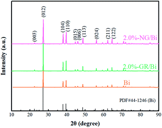
Fig. 1 shows the XRD spectra of the Bi, 2.0%-NG/Bi and 2.0%-GR/Bi. The XRD spectrum of the pure Bi exhibited characteristic peaks at 27.1° (012), 37.9° (104) and 39.8° (110), which were in consistent with the standard Bi (JCPDS no. 44-1246).17 Meanwhile, the XRD patterns of 2.0%-NG/Bi and 2.0%-GR/Bi synthesized by chemical precipitation showed same characteristic peaks as pure Bi. This result indicated that the addition of NG and GR would not affect the growth of Bi, but also make the peak intensity of mixtures more sharper, suggesting that the crystal structure of Bi phase in 2.0%-NG/Bi and 2.0%-GR/Bi composites were more perfect, and the introduction of NG and GR were more favorable for the growth of the Bi. Additionally, the characteristic peaks corresponding to NG and GR were hardly found, probably owed to the shielding effect caused by violent peak intensity of Bi and the low content of NG and GR.18–20Subsequently, in order to verify the successful introduction N-doped graphene and proved the surface chemical states in 2.0%-NG/Bi and Bi, XPS was conducted. The survey XPS spectrum exhibited that 2.0%-NG/Bi and Bi contained Bi, C and O elements, and no other impurities were observed (Fig. 2a). It was worth noting that the intensity of C peak in 2.0%-NG/Bi was stronger than Bi, which might be due to the addition of N-doped graphene. The Bi 4f diagram of 2.0%-NG/Bi showed four characteristic peaks located at 156.6 eV, 159.1 eV, 161. 9 eV and 164.4 eV, respectively (Fig. 2b). The characteristic peaks of 156.6 eV and 161.9 eV were in agreement with the Bi–Bi bonds, and 159.1 eV and 164.4 eV belong to the Bi–O bonds.17 This proved that Bi was successfully synthesized in 2.0%-NG/Bi, but the appearance of Bi–O bonds was due to the easy oxidation of Bi.17 The N 1s XPS spectrum of 2.0%-NG/Bi given in Fig. 2c revealed the existence of pyridine N (∼398.2 eV), pyrrolic N (∼400.4 eV) and graphite N (∼401.8 eV) in 2.0%-NG/Bi.15,21 The 2.0%-NG/Bi C 1s XPS spectrum (Fig. 2d) could be resolved into five peaks. The peak at 284.6 eV was originated from graphene-like sp2 hybridized carbon and demonstrated that most of the C atoms were embedded in the graphene lattice. The others situated at 285.9 eV, 286.6 eV, 287.1 eV and 289.0 eV were in accorded with C![[double bond, length as m-dash]](https://www.rsc.org/images/entities/char_e001.gif) N, C–O, C–N and O–C
N, C–O, C–N and O–C![[double bond, length as m-dash]](https://www.rsc.org/images/entities/char_e001.gif) O species, respectively.21 These results illustrated that N elements has been doped into the graphene structure by high temperature ammonia gas calcination.
O species, respectively.21 These results illustrated that N elements has been doped into the graphene structure by high temperature ammonia gas calcination.
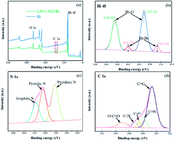 | ||
| Fig. 2 XPS spectra of (a) survey of 2.0%-NG/Bi and Bi, (b) Bi 4f, (c) N 1s and (d) C 1s for 2.0%-NG/Bi. | ||
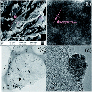
Fig. 3 exhibits the morphology of 2.0%-NG/Bi. The interconnection and agglomeration of Bi spheres on the surface NG sheets was observed and the average of the Bi nanoparticles was 100 nm (Fig. 3a). Although the restacking of the nanoparticles was not prevented, the existence of NG nanosheets could be a barrier to alleviate the formation of larger interconnected aggregates of Bi. Further HRTEM investigations revealed lattice stripes with a lattice spacing of 0.328 nm were found, which was match well with the (012) facet of the Bi phase (Fig. 3b).17 Fig. 3c also confirmed that Bi spheres were randomly distributed on the surface of NG nanosheets. Moreover, HRTEM images demonstrated that an intimate metal–semiconductor interface was formed within the NG/Bi nanohybrids, favorable for photoinduced charge carrier's separation and transfer between the Bi nanoparticles and NG sheets.
3.2 Plasmonic feature of BiNPs
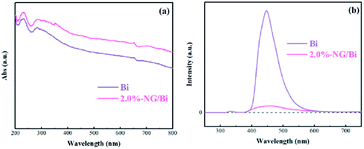
The SPR characteristic of Bi and 2.0%-NG/Bi were examined by the UV-vis DRS spectra (Fig. 4a). It was worth noting that the NG-modified Bi had a strong absorption of light including visible light or UV light, which could be ascribed to the NG playing a role in utilizing light and the SPR effect of Bi.22 This enhanced light absorptions could facilitate the production of more photogenerated electrons–holes to improve the photocatalytic efficiency of NG/Bi nanocomposites.To investigate the separation efficiency of photocatalyst photogenerated carriers, the as-prepared sample was subjected to PL detection.23 Normally, an inferior PL intensity demonstrates a humble recombination rate of the photo-driven electron–hole pairs under light illumination. The PL peak intensity of Bi was sharply reduced after NG modification (Fig. 4b), which could be put down to the fact that the addition of N-doped GR accelerated the transfer of hot electron generated by Bi, thereby inhibiting the recombination of photogenerated carriers.
3.3 Photocatalytic NO removal
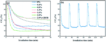
The as-prepared GR/Bi and NG/Bi photocatalysts were used to the photocatalytic removal of gas phase ppb-level NO in a continuous reactor under UV light condition. It was well known that NO exposed to UV light at room temperature cannot be self-degradable.24 The photocatalytic performance of the sample was judged by the removal ratio of NO. Fig. 5a revealed that the photocatalytic removal ratio of NO by pure Bi nanoparticles was 40.8% after 30 minutes UV light irradiation. The photocatalytic NO removal rate of 0.4%-NG/Bi, 0.8%-NG/Bi, 1.2%-NG/Bi, 1.6%-NG/Bi and 2.0%-NG/Bi were about 48.1%, 29.6%, 28.9%, 48.5% and 49.5%, respectively. Moreover, as the NG content increased, the photocatalytic property trend seemed dispersive. The photocatalytic activity of 0.8%-NG/Bi and 1.2%-NG/Bi were sharply hampered, while 0.4%-NG/Bi, 1.6%-NG/Bi and 2.0%-NG/Bi were surged at the range of 48.1% to 49.5%. The reason for this difference was because NG had a dual effect in the system. Under the synergistic effect of the two, it played a different role in promoting photocatalytic reactions. Firstly, NG could promote the absorption of light by the system. Secondly, NG as a good conductor of electrons could promote the transfer of electrons. When the amount of NG was small (0.4%), both effects were positively promoted. When the amount of NG was increased (such as 0.8% and 1.2%), due to the structural characteristics of the large specific surface area of NG,11 it might cause the masking of the light absorption sites of Bi, although the electron conduction was not affected, the photocatalytic performance was still degraded at this time. When the loading of NG was increased to 2.0%, although the above-mentioned negative effects still exist, at this time, the electronic conduction performance of the system was greatly improved (Fig. 4b), under the overall effect, the photocatalytic reaction was significantly improved. This result demonstrated that the content of NG greatly affected the actives of the as-prepared photocatalysts. Notably, the extremely high performance of 2.0%-NG/Bi (49.5%) outperformed that of 2.0%-GR/Bi (37.0%) under the same test conditions as shown in Fig. 5a. More detailed, the photocatalytic performance of 2.0%-NG/Bi was slightly reduced to 43.1% after five cycles (Fig. 5b). Overall, these declared a compelling evidence that the N-doped graphene modified Bi led to an improvement in photocatalytic NO oxidation. The elevated photocatalytic property was ascribed to the fact that the introduction of N-doped graphene promoted the absorption of light and speeded up the transfer of hot electrons emerged by the SPR effect of Bi.3.4 Active species trapping experiments
To further reveal the generation of active species of 2.0%-NG/Bi under UV light irradiation, spin-trapping ESR spectra were implemented (Fig. 6). As shown in Fig. 6, the DMPO–·OH and DMPO–·O2− signal peaks were not observed in the dark condition, and the peak intensity increased with the illumination time. After 2.0%-NG/Bi was irradiated by UV light for 4 minutes, the DMPO–·O2− signal peak appeared, while the DMPO–·OH signal peak was still absent. When the illumination time was 8 minutes, the peak intensity of the DMPO–·O2− signal was strengthened, and the DMPO–·OH signal peak appeared. After 12 minutes of light irradiation, the peak intensity of DMPO–·O2− and DMPO–·OH signals were significantly enhanced. Combined with Fig. 5a analysis, the removal rate of NO in 2.0%-NG/Bi has reached 45.0% in the first 4 minutes, accounting for 90.0% of the total removal rate. As could be seen from Fig. 6, when 2.0%-NG/Bi was exposed to UV light for 4 minutes, only ·O2− was produced, implying ·O2− was the dominant active species for photocatalytic removal of NO by NG/Bi nanocomposites.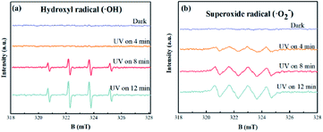 | ||
| Fig. 6 DMPO spin-trapping ESR spectra of 2.0%-NG/Bi nanohybrids in aqueous dispersion for DMPO–·OH (a) and in methanol dispersion for DMPO–·O2− (b). | ||
3.5 Mechanism
To further prove that the addition of N-doped graphene accelerated the transfer of hot electrons, we performed photoelectrochemical tests on Bi and 2.0%-NG/Bi, respectively. Fig. 7a showed that the photocurrent response of 2.0%-NG/Bi was significantly higher than that of Bi under UV light. Fig. 7b exhibited the EIS spectrum of the corresponding samples. It was well established that the smaller the diameter of the circle of the EIS plots of the sample, the smaller the resistance at the interface.25 It was obviously that the diameter of the circle of the EIS plots of 2.0%-NG/Bi nanocomposites was much smaller than that of pure Bi (Fig. 7b). These phenomena represented that the introduction of N-doped graphene promoted the transfer of hot electrons and the separation of carriers generated by Bi, which was in lined with the results of the PL spectrum.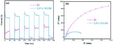 | ||
| Fig. 7 Photocurrent transient (a) and EIS spectra (b) of Bi-NPs and 2.0%-NG/Bi nanohybrids under 280 nm UV light irradiation. | ||
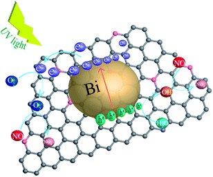
Based on the above experiments, the mechanism of photocatalytic degradation of NO over NG/Bi samples under UV light was proposed (Fig. 8). Since N-doped graphene was added during the synthesis of Bi, this not only reduced the agglomeration of Bi but also formed a heterojunction between the two, and their coupling afforded the increased absorption of light and more active sites of the photocatalytic reaction, resulting in more efficient carriers transferring across the interface. When NG/Bi was exposed to UV light, the SPR feature caused Bi nanoparticles to transform the incident photon energy into surface plasmon resonance. The resulting non-radiative decay would provide the hot electrons.26,27 Then, the hot electrons quickly transferred to the N-doped graphene that was tightly connected to the Bi. In addition, the presence of π–π bonds conjugated structure in N-doped graphene made it advantageous for the conduction of electrons.28 Then, the electrons reacted with the oxygen adsorbed on the surface of the catalyst to form ·O2−, which then oxidized NO to generated NO3−.2,29,30 Moreover, ·OH generated by the reaction of holes and water could also oxidize NO to form NO2.30,31 ESR test proved that ·O2− was the superior active substance, suggesting that the ·O2− photocatalytic reaction oxidized NO as the main removal path.
4. Conclusions
In summary, the nitrogen-doped graphene/Bi nanohybrid had been successfully fabricated via an eco-friendly synthesis method. The Bi nanoparticles were closely assembled on the N-doped graphene nanosheets, which was proved by XPS and SEM. Moreover, NG/Bi could efficiently enhance the absorption of light in contrast to pure Bi. In addition, PL and photoelectrochemical tests have shown that the addition of NG allowed for more efficient separation of hot carriers produced by SPR effect of Bi. NG/Bi exhibited a promising photocatalytic performance and stability for NO removal as compared to counterparts. Combined with the ESR diagram, the detailed mechanism of photocatalytic oxidation of NO by NG/Bi nanoparticles was proposed.Conflicts of interest
There are no conflicts to declare.Acknowledgements
This project was supported by the National Natural Science Foundation of China (No. 51402030); Natural Science Foundation of the Chongqing Science and Technology Commission (cstc2017jcyjBX0028); Science and Technology Research Program of Chongqing Municipal Education Commission (KJZD-K201800703) and Chongqing Ecology and Environment Bureau (2019-127).References
- F. Dong, Z. W. Zhao, Y. J. Sun, Y. X. Zhang, S. Yan and Z. B. Wu, Environ. Sci. Technol., 2015, 49, 12432–12440 CrossRef CAS PubMed.
- S. N. Nguyen, T. K. Truong, S.-J. You, Y.-F. Wang, T. M. Cao and V. V. Pham, ACS Omega, 2019, 4, 12853–12859 CrossRef CAS PubMed.
- T. H. Huy, D. P. Bui, F. Kang, Y.-F. Wang, S.-H. Liu, C. M. Thi, S.-J. You, G.-M. Chang and V. V. Pham, Chemosphere, 2019, 215, 323–332 CrossRef CAS PubMed.
- C. Wang, M. Fu, J. Cao, X. Wu, X. Hu and F. Dong, Chem. Eng. J., 2020, 385, 123833 CrossRef.
- P. Chen, H. Liu, Y. Sun, J. Li, W. Cui, L. a. Wang, W. Zhang, X. Yuan, Z. Wang, Y. Zhang and F. Dong, Appl. Catal., B, 2020, 264, 118545 CrossRef.
- H. Cheng, B. Huang, P. Wang, Z. Wang, Z. Lou, J. Wang, X. Qin, X. Zhang and Y. Dai, Chem. Commun., 2011, 47, 7054–7056 RSC.
- L. Wu, F. Li, Y. Xu, J. W. Zhang, D. Zhang, G. Li and H. Li, Appl. Catal., B, 2015, 164, 217–224 CrossRef CAS.
- Q. Zhang, Y. Zhou, F. Wang, F. Dong, W. Li, H. Li and G. R. Patzke, J. Mater. Chem. A, 2014, 2, 11065–11072 RSC.
- F. Dong, T. Xiong, Y. J. Sun, Z. W. Zhao, Y. Zhou, X. Feng and Z. B. Wu, Chem. Commun., 2014, 50, 10386–10389 RSC.
- C. Clavero, Nat. Photonics, 2014, 8, 95 CrossRef CAS.
- O. C. Compton and S. T. Nguyen, Small, 2010, 6, 711–723 CrossRef CAS PubMed.
- X.-Y. Zhang, H.-P. Li, X.-L. Cui and Y. Lin, J. Mater. Chem., 2010, 20, 2801–2806 RSC.
- Q.-P. Luo, X.-Y. Yu, B.-X. Lei, H.-Y. Chen, D.-B. Kuang and C.-Y. Su, J. Phys. Chem. C, 2012, 116, 8111–8117 CrossRef CAS.
- Q. Li, X. Li, S. Wageh, A. A. Al-Ghamdi and J. Yu, Adv. Energy Mater., 2015, 5, 1500010 CrossRef.
- H. Wang, T. Maiyalagan and X. Wang, ACS Catal., 2012, 2, 781–794 CrossRef CAS.
- X. Li, H. Wang, J. T. Robinson, H. Sanchez, G. Diankov and H. Dai, J. Am. Chem. Soc., 2009, 131, 15939–15944 CrossRef CAS.
- X. Yuan, Z. Feng, J. Zhao, J. Niu, J. Liu, D. Peng and X. Cheng, Catalysts, 2018, 8, 426 CrossRef.
- D. Cai and M. Song, J. Mater. Chem., 2007, 17, 3678–3680 RSC.
- K. Singh, A. Ohlan, V. H. Pham, R. Balasubramaniyan, S. Varshney, J. Jang, S. H. Hur, W. M. Choi, M. Kumar, S. K. Dhawan, B.-S. Kong and J. S. Chung, Nanoscale, 2013, 5, 2411–2420 RSC.
- X. Li, W. Zhang, W. Cui, Y. Sun, G. Jiang, Y. Zhang, H. Huang and F. Dong, Appl. Catal., B, 2018, 221, 482–489 CrossRef CAS.
- C. Zhang, L. Fu, N. Liu, M. Liu, Y. Wang and Z. Liu, Adv. Mater., 2011, 23, 1020–1024 CrossRef CAS PubMed.
- S. Weng, B. Chen, L. Xie, Z. Zheng and P. Liu, J. Mater. Chem. A, 2013, 1, 3068–3075 RSC.
- X. Yuan, X. Wu, Z. Feng, W. Jia, X. Zheng and C. Li, Catalysts, 2019, 9, 624 CrossRef CAS.
- F. Dong, A. Zheng, Y. Sun, M. Fu, B. Jiang, W.-K. Ho, S. C. Lee and Z. Wu, CrystEngComm, 2012, 14, 3534–3544 RSC.
- H. Shen, H. Wei, Z. Pan, Y. Lu and Y. Wang, Appl. Surf. Sci., 2017, 423, 403–416 CrossRef CAS.
- M. L. Brongersma, N. J. Halas and P. Nordlander, Nat. Nanotechnol., 2015, 10, 25 CrossRef CAS PubMed.
- V. Giannini, A. I. Fernández-Domínguez, S. C. Heck and S. A. Maier, Chem. Rev., 2011, 111, 3888–3912 CrossRef CAS PubMed.
- L. Jia, D.-H. Wang, Y.-X. Huang, A.-W. Xu and H.-Q. Yu, J. Phys. Chem. C, 2011, 115, 11466–11473 CrossRef CAS.
- M. Ou, S. Wan, Q. Zhong, S. Zhang, Y. Song, L. Guo, W. Cai and Y. Xu, Appl. Catal., B, 2018, 221, 97–107 CrossRef CAS.
- H. Ren, P. Koshy, W.-F. Chen, S. Qi and C. C. Sorrell, J. Hazard. Mater., 2017, 325, 340–366 CrossRef CAS PubMed.
- Q. Zhang, Y. Huang, S. Peng, Y. Zhang, Z. Shen, J.-j. Cao, W. Ho, S. C. Lee and D. Y. H. Pui, Appl. Catal., B, 2017, 204, 346–357 CrossRef CAS.
Footnote |
| † Electronic supplementary information (ESI) available. See DOI: 10.1039/c9ra10001f |
| This journal is © The Royal Society of Chemistry 2020 |

