 Open Access Article
Creative Commons Attribution 3.0 Unported Licence
Cyclometalation of lanthanum(III) based MOF for catalytic hydrogenation of carbon dioxide to formate†
Piwai Tshumaab,
Banothile C. E. Makhubela b,
Lars Öhrström
 c,
Susan A. Bourne
 d,
Nabanita Chatterjeed,
Isaac N. Bease,
James Darkwabe and
Gift Mehlana
 *a
*a
aDepartment of Chemical Technology, Faculty of Science and Technology, Midlands State University, Private Bag 9055, Senga Road, Gweru, Zimbabwe
bDepartment of Chemistry, Faculty of Science, University of Johannesburg, Kingsway Campus: C2 Lab 328, Auckland Park, 2006, South Africa
cChalmers University of Technology, Department of Chemistry and Chemical Engineering, Physical Chemistry Room 9029, Göteborg, Sweden
dUniversity of Cape Town, Department of Chemistry, Faculty of Science, PD Hahn Building 7701 Rondebosch, Cape Town, South Africa
eDepartment of Natural Resources and Materials, Botswana Institute of Technology Research and Innovation, Maranyane House, Private Bag 0082 Gaborone, Botswana. E-mail: mehlanag@staff.msu.ac.zw
First published on 22nd January 2020
Abstract
The hydrogenation of carbon dioxide (CO2) to formic acid is of great importance due to its useful properties in the chemical industry. In this work, we have prepared a novel metal–organic framework (MOF), JMS-1, using bipyridyl dicarboxylate linkers, with molecular formula [La2(bpdc)3(DMF)3]n. Network analysis of JMS-1 revealed a new 7-connected topology (zaz). The MOF backbone of the activated phase (JMS-1a) was functionalized by cyclometalation using [RuCl2(p-cymene)]2 to produce Ru(II)@JMS-1a. Both JMS-1a and Ru(II)@JMS-1a were able to convert CO2 in the presence of hydrogen to formate. Ru(II)@JMS-1a displayed outstanding conversion evidenced by a yield of 98% of formate under optimized conditions of total pressure 50 bar (CO2/H2 = 1![[thin space (1/6-em)]](https://www.rsc.org/images/entities/char_2009.gif) :
:![[thin space (1/6-em)]](https://www.rsc.org/images/entities/char_2009.gif) 4, temperature 110 °C, time 24 h, 5 mmol KOH, 8 mL ethanol). This work is significant in providing new strategies of incorporating active catalytic centres in MOFs for efficient and selective conversion of CO2 to formate.
4, temperature 110 °C, time 24 h, 5 mmol KOH, 8 mL ethanol). This work is significant in providing new strategies of incorporating active catalytic centres in MOFs for efficient and selective conversion of CO2 to formate.
Introduction
The conversion of carbon dioxide to high value chemicals is of global interest owing to the dangers posed by this greenhouse gas to the environment. Carbon dioxide is also considered as a cheap and renewable source of carbon and its conversion to formic acid is of interest to the chemical industry. The world production of formic acid is around 700![[thin space (1/6-em)]](https://www.rsc.org/images/entities/char_2009.gif) 000 tons per year, mostly from combining methanol and carbon monoxide.1 In addition to current use, one can view formic acid produced from renewable H2 and CO2 as a way to store energy.2,3
000 tons per year, mostly from combining methanol and carbon monoxide.1 In addition to current use, one can view formic acid produced from renewable H2 and CO2 as a way to store energy.2,3
During the past decades extensive research on conversion of carbon dioxide to formate or methanol has been accomplished using both homogeneous catalysts and heterogeneous catalysts.4–6 The challenge with using homogenous catalysts, which prove to operate under more milder conditions than their heterogeneous counterparts, is the separation of formic acid or formate adducts from the catalyst and the reaction media. This is because the homogeneous catalyst present in the reaction media can easily convert the produced formic acid/formate adduct back to CO2 and H2 during the product isolation process. In light of this, it is of paramount importance to design and develop heterogeneous catalysts which can be easily secluded via simple filtration prior to the product separation step and can be continuously recycled for successive runs.
Metal–organic frameworks (MOFs) are a new class of crystalline materials which have generated much interest, owing to their potential applications in gas storage,7 separation,8 catalysis,9 sensing10 etc. The often porous and highly ordered nature of these structures provides a unique platform to extend their applications as multifunctional materials. These materials can in principle be tailored to achieve desirable properties and it has been shown that MOFs are capable of capturing and storing gases such as CO2 (ref. 11 and 12) and H2.13 Several strategies have been developed to enhance the volumetric uptake of these gases by MOFs such as the introduction of open metal sites as well as including the amine groups within the MOF pores to enhance the uptake of CO2.14
Recently, there has been a growing interest in the use of MOFs for conversion of CO2 to useful chemicals. The majority of these studies have been focusing on water stable Zr-based MOFs,12,15–21 with the catalytically active centres introduced to the MOF backbone by post synthetic metalation of a bipyridine linker. Interestingly, none of these publications report on the activity of the parent MOF towards reduction of CO2 but rather focus on the metals introduced into the pores of the MOF such as ruthenium, rhodium and iridium.
In this contribution, we have prepared a La(III)-based MOF, JMS-1 (Johannesburg and Midlands State) constructed from bipyridyl decarboxylate linkers. Topological analysis of the network revealed a hitherto unobserved 3D net. The MOF's structural integrity changed slightly upon encapsulation of [Ru(II)Cl(p-cymene)] complex through activation of the C–H bond which indicates framework flexibility.22 Catalytic studies showed that JMS-1a and Ru(II)@JMS-1 converted CO2 to formate. Our results demonstrate that incorporation of the [Ru(II)Cl(p-cymene)] complex into the MOF enhances the yield of formate produced.
Experimental section
Materials and methods
All materials used in this study were of analytical grade and used without further purification. Lanthanum chloride (LaCl3·7H2O), was purchased from Sigma-Aldrich and used as received.Preparation of [La2(bpdc)3(DMF)4]n (JMS-1)
2,2′-Bipyridine-4,4′-dicarboxylic acid (H2bpdc) (29 mg, 0.113 mmol) and LaCl3·7H2O (110 mg, 0.327 mmol) were mixed in 11 mL of DMF. The reaction mixture was stirred for 15 minutes and heated in an oven at 110 °C for 48 h. Colorless dendrite-like crystals were obtained.Single crystal structure determination
| JMS-1 | |
|---|---|
| Empirical formula | C45H39La2N9O15 |
| Formula weight | 1223.67 |
| Temperature/K | 173(2) |
| Crystal system | Orthorhombic |
| Space group | Pna21 |
| a/Å | 18.0826(12) |
| b/Å | 13.3216(9) |
| c/Å | 21.9623(15) |
| Volume/Å3 | 5290.5(6) |
| Z | 4 |
| ρcalc g/cm−3 | 1.5361 |
| F(000) | 2388 |
| Crystal size (mm) | 0.111 × 0.05 × 0.07 |
| Index ranges (h, k, l max) | 23, 17, 28 |
| Reflections collected | 47![[thin space (1/6-em)]](https://www.rsc.org/images/entities/char_2009.gif) 417 417 |
| Two theta range | 1.788–27.556 |
| Independent reflections | 11![[thin space (1/6-em)]](https://www.rsc.org/images/entities/char_2009.gif) 053 053 |
| Goodness-of-fit on F2 | 1.036 |
| Final R indexes [I ≧ 2σ(I)] | 0.0546 |
| Final R indexes [all data] | 0.1596 |
| Largest diff. peak/hole/eÅ−3 | 1.08/−1.00 |
NMR studies
1H NMR spectra were recorded on a Bruker Ultrashield 400 MHz spectrometer. Spectrometer values were reported relative to the internal standard tetramethylsilane (δ 0![[thin space (1/6-em)]](https://www.rsc.org/images/entities/char_2009.gif) :
:![[thin space (1/6-em)]](https://www.rsc.org/images/entities/char_2009.gif) 00). All chemical shifts were reported in ppm.
00). All chemical shifts were reported in ppm.
Topological analysis
The network topologies discussed in this article were obtained using the free software programs SYSTRE,25b and TOPOS PRO,25c and we discuss the topologies using the three-letter symbols in the web-based and free Reticular Chemistry Structural Resource database, RCSR.25dPreparation of JMS-1a and Ru(II)@JMS-1a
JMS-1 was activated by soaking the as-made crystals in methanol for 24 h to allow for the exchange of DMF with a low boiling solvent. The soaked crystals were then heated under a vacuum for 24 h at 78 °C to give the activated phase JMS-1a. Complete removal of the solvent molecules was confirmed by TGA analysis in Fig. S1† which showed no weight loss until decomposition. Cyclometalation of the activated JMS-1a was carried according to a method reported in literature for a homogeneous system.26 It is a direct method to produce stable cyclometallated ruthenium(II) complexes with [RuCl2(p-cymene)]2 precursor, via the C–H bond deprotonation in the presence of sodium acetate at room temperature in methanol. In a typical experiment, 50 mg of the activated crystalline powder was soaked in 10 mL methanolic and sodium acetate solution of [RuCl2(p-cymene)]2 for 24 h at room temperature. Successful preparation of Ru(II)@JMS-1a was confirmed by XPS studies. The amount of Ru present in Ru(II)@JMS-1a was determined by ICP-OES and found to be 0.4% by weight. Elemental analysis of JMS-1a found % C 43.15, % N 8.45, % H 1.75 calculated, % C 43.05, % N 8.37, % H 1.79: Ru(II)@JMS-1a, found % C 44.89, % N 7.88, % H 1.98. The increase in the percentage carbon content in Ru(II)@JMS-1a suggests the presence of p-cymene in the functionalized MOF.Gas sorption measurements
Porosity and surface properties of the samples were analyzed using Micromeritics ASAP 2460 surface and porosity analyzer. Prior to analysis, the samples were degassed using nitrogen gases (N2) at 90 °C for 12 hours, then at 150 °C for 8 h. Thereafter, the samples were weighed and analyzed at 77 K using N2 as a probe gas.Catalytic studies
In a typical experiment the catalysts were charged into a Teflon-lined stainless-steel reactor equipped 5 mmol KOH in 8 mL ethanol. The reactor was first purged with nitrogen gas three times to remove air from the vessel. This was followed by pressurizing the reactor with CO2 and hydrogen (CO2/H2 = 1![[thin space (1/6-em)]](https://www.rsc.org/images/entities/char_2009.gif) :
:![[thin space (1/6-em)]](https://www.rsc.org/images/entities/char_2009.gif) 1 to 1
1 to 1![[thin space (1/6-em)]](https://www.rsc.org/images/entities/char_2009.gif) :
:![[thin space (1/6-em)]](https://www.rsc.org/images/entities/char_2009.gif) 3) at room temperature. The catalytic reactions were carried out within a temperature range of 90 °C to 120 °C while stirring was maintained at 945 rpm. Upon completion of the reaction, the reactor was cooled to room temperature, the pressure was released before the product was collected into the sample vial. The yield of formate produced was calculated as moles of formate produced divided by the moles of the base used (see example 1 in the ESI†).
3) at room temperature. The catalytic reactions were carried out within a temperature range of 90 °C to 120 °C while stirring was maintained at 945 rpm. Upon completion of the reaction, the reactor was cooled to room temperature, the pressure was released before the product was collected into the sample vial. The yield of formate produced was calculated as moles of formate produced divided by the moles of the base used (see example 1 in the ESI†).
The solid catalyst was washed several times with ethanol and dried in an oven at 100 °C for recycling. The reproducibility of the catalytic results was confirmed by repeated experiments.
Results and discussion
Structural description
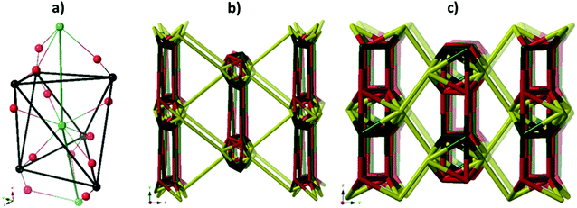
Single crystal X-ray diffraction revealed that JMS-1 crystallises in the orthorhombic crystal system and space group Pna21. In the asymmetric unit of JMS-1, we modelled three bpdc linkers, two crystallographic independent La(III) centres and a total of three DMF molecules. The structure of JMS-1 is made up of La2C3O6 secondary building unit (SBU) rod which grow along the b-axis (Fig. 1a). The SBUs are connected by the bpdc linkers which propagates along the a-axis to give a three-dimensional structure. The void space found in JMS-1 is reduced by the presence of the bpdc linkers which connects the SBU along the b–c plane. Each La(III) is coordinated to two DMF molecules and six oxygen atoms of the bpdc linker to furnish a square antiprismatic geometry as illustrated in Fig. 1b. One of the coordinated DMF molecules on each of La(1) and La(2) was found to be disordered over two positions and the atoms were refined isotopically. The second coordinated DMF on each of the metal ions in the asymmetric unit was modelled with 50% site occupancy as suggested by TGA analysis. Due to high temperature factors, the atoms of these DMF molecules were also refined isotopically. The bpdc linker assumes a bridging bidentate mode connecting two La(III) metal ions. The La–O bond distances ranges from 2.41(13) to 2.660(4) Å.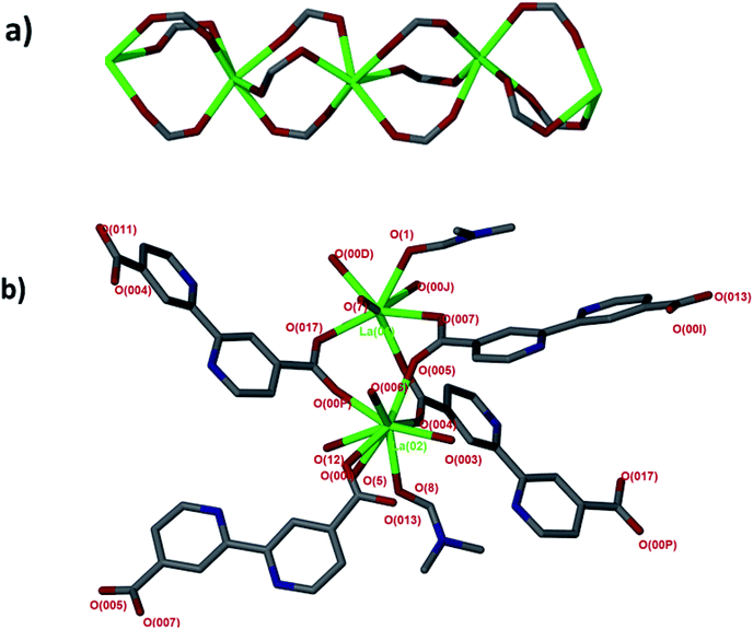 | ||
| Fig. 1 (a) SBU rod generated in situ, (b) coordination environment around the two La(III) modelled in the asymmetric unit. | ||
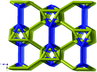
Analysis of the channels (window dimensions of approximately 6.8 × 5.2 Å) found in JMS-1 which run along the b-axis by PLATON27 shows that they occupy 41% of the unit cell volume. These channels are decorated by DMF molecules that are coordinated to the La(III) metal ion. Fig. 2 illustrates the channels found in JMS-1.
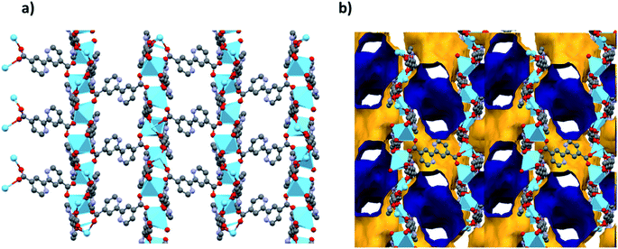 | ||
| Fig. 2 (a) Packing diagram of JMS-1 viewed along the b-axis drawn in (a) and stick form and (b) the voids found in JMS-1, the outer and inner surface is shown in yellow and blue respectively. | ||
Thermal analysis of JMS-1by TGA (Fig. S1†) shows a 16.5% weight loss between 150 and 250 °C which corresponds to loss of three DMF molecules modelled in the crystal structure of JMS-1 (calculated 17.89). The TGA thermogram is featureless between 320 and 450 °C an indication of high thermal stability. Decomposition of the framework is observed above 460 °C. The phase purity of JMS-1 was confirmed from the excellent agreement between the experimental PXRD pattern of JMS-1 and the calculated PXRD pattern from the single crystal structure (Fig. 3).
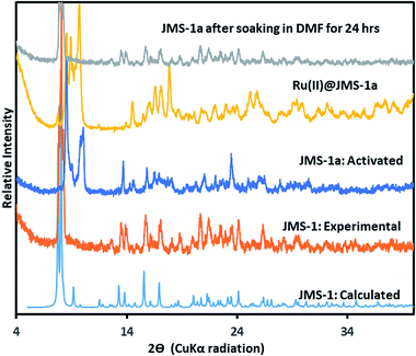 | ||
| Fig. 3 PXRD patterns of JMS-1: calculated, JMS-1: experimental, JMS-1a: activated and the [Ru(II)p-cymene] loaded MOF (Ru(II)@JMS-1a). | ||
The fact that compound JMS-1a has coordinated DMF molecules which can be removed by guest exchange followed by thermal treatment makes it a suitable candidate for catalysis. Removal of coordinated guest molecules has been reported to provide free open metal sites which enhances adsorption of hydrogen and carbon dioxide in the pores.28,29 JMS-1a and Ru(II)@JMS-1a are thermally stable (Fig. S1†) which makes them good catalysts within the temperature range at which catalysis is carried out.
Topological analysis of the network found in JMS-1
MOFs based on rods, that is when there is a polynuclear coordination entity propagating infinity in one dimension and connecting to other rods by bridging ligands, (infinite metal SBU:s) has received attention lately.30,31 One reason is that their topologies do not generally allow for interpenetration of a second network, and another is that they often display “breathing” properties (for example of the MIL-53 types), i.e. they may change volume on uptake or discharge of guest molecules.32 Compared to the topologies of MOFs based on finite metal SBU:s or single metal nodes that often display one of the high symmetry nets,33,34 rod based MOF:s have an intriguing diversity. One recent example is a bismuth based MOF that, although not built of anything more complex than 1,3,5-benzenetricarboxylate (BTC3) ligands and Bi3+ ions, has a unprecedented topological complexity with 54 unique nodes and 135 edges, that is the net has transitivity 54![[thin space (1/6-em)]](https://www.rsc.org/images/entities/char_2009.gif) 135.35
135.35
A simple approach considers the La-carboxylate rod in compound JMS-1 as a featureless rod, except for the links to the bridging ligands. We then consider rod-centered nodes at the centroids of the tris-carboxylate binding sites. This gives a five-connected soe-net as seen in Fig. 4.
This conspicuously looks like the same approach that we use with for example paddle-wheel four-connected SBU:s like the [Cu2(–CO2)4] in for example HKUST-1 with the underlying topology tbo.36 There are two problems, however.
The general deconstruction approach where a polynuclear coordination entity is contracted to one point obviously will contract any rod to a single point and thus reduce a 3D net to a 2D net, in this case the 6-connected hxl-net. The other issue is that the divisions we have done on the infinite polynuclear entity is arbitrary and difficult to generalize. In the approach giving the soe-net it is necessary to think of the net as constructed by polygons, triangles in this case, intersected by the rod. While the triangles are straight forward for this structure, this is not always the situation. This is not necessarily a problem from the analysis point of view, but the relation between theses single links, or the triangles as they are in our case, is lost. And the relation between the links projecting from the rod is completely determined by the topology of the rod. Thus, important structural information, like the existence of isomers, is potential lost if this approach is used. In this respect the problem is similar to the discussion of the “all node” deconstruction approach considering all branch points of the linkers, and the “single node” method considering only components mixed where the latter also will miss potential isomers.14
As suggested by O'Keeffe and coworkers,37 we instead take the carbonyl carbons as the points of extension and create with them the simplest geometrical forms that describe the features of the rod. Often these descriptions turn out to be ladders, helices or linked polyhedra. In our case, the rod can be described as face-sharing octahedra, see Fig. 5.
As every vertex in an octahedron is four-connected, face sharing the octahedra will mean every vertex is now six-connected, and bridging the rods with the ligands means we will have a seven-connected net. The most regular way of doing this is the sct-net, a pleasingly symmetric net where each octahedron have six links protruding from it with 60° angles if projected along the a-axis (Fig. 6).32 On the contrary, the zaz-net in the present structure have two pairs of two parallel links connecting the rods, resulting in a three-nodal net that is nevertheless symmetric and esthetically attractive.
Functionalisation of JMS-1a
The catalyst Ru(II)@JMS-1a was prepared as described in the experimental section. Comparison of the PXRD pattern of JMS-1a and JMS-1 suggest formation of a new phase upon activation. However, when JMS-1a is soaked in DMF for 24 h it reverts back to JMS-1 indicating a reversible structural transformation (Fig. 3). Upon cyclometalation, a new phase is formed as evidenced by the appearance of new diffraction peaks between which are not present in the parent JMS-1a indicative of framework flexibility. The FTIR (Fig. S2†) of JMS-1a and Ru(II)@JMS-1a which have similar characteristic bands in the carboxylate stretching region. This observation confirms that the binding mode of the carboxylate moiety is not affected during cyclometalation of the JMS-1a.XPS analysis
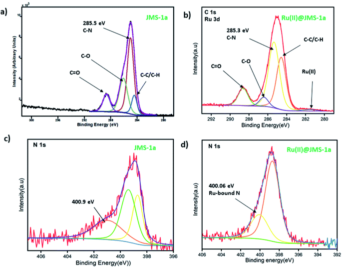
JMS-1a and Ru@JMS-1a were ground in order to evaluate the chemical state of the elements using XPS analysis. Initial state effects or chemical shifts, reflect the changes in the electronic structure of the material. Cyclometalation is a direct method to produce stable cyclometalated ruthenium(II) complexes with [RuCl2(p-cymene)]2 precursor, via the C–H bond deprotonation in the presence of sodium acetate at room temperature in methanol.38 The cyclometalation of JMS-1a can easily be followed using XPS studies. During this reaction we expected the nitrogen and carbon of the linker to bind to the ruthenium(II). Successful coordination of Ru(II) to nitrogen and carbon should be reflected by a decrease in the binding energy carbon and nitrogen. Evidence of successful grafting of the Ru(II) complex to the MOF is provided by the C 1s binding energy which shifts from 285.5 eV in JMS-1a to 285.3 eV in Ru(II)@JMS-1a (Fig. 7a and b). The species indicated in Fig. 7 a and b is consistent with what is in the structure of JMS-1a and Ru(II)@JMS-1a. In the case of N 1s binding energy (Fig. 7c and d), one identified peak is correlated with the change in the chemistry of JMS-1a. JMS-1a shows that the binding energy of N 1s is located at 400.9 eV. Upon cyclometalation with the Ru(II) complex this energy shifts to 400.06 eV suggesting that the nitrogen atom donated electrons to the Ru(II) ion. The observed shifts are consistent with low ruthenium loading content of 0.4% in Ru@JMS-1a.Sorption studies
Surface characterisation studies by BET (Fig. 8a) revealed a significant reduction in the BET surface are from 112 g m−2 to 58 g m−2 upon cyclometalation. The observed decrease in the surface area is ascribed to the blockage of the pores by the Ru(II)p-cymene complex.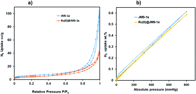 | ||
| Fig. 8 (a) Nitrogen and (b) hydrogen adsorption and desorption studies of JMS-1a and Ru(II)@JMS-1a at 77 K. | ||
This is evidence of successful incorporation of Ru(II)p-cymene within the pores of JMS-1a. The adsorption isotherms of JMS-1a and Ru(II)@JMS-1a show type 1 isotherm at very low pressure (<0.4 P/Po) as illustrated in Fig. S3.† Similar behaviour was reported by Liang and co-workers.39 Hydrogen adsorption isotherms of JMS-1a and Ru(II)@JMS-1a are depicted in Fig. 9b. At 77 K and 800 mmHg the aforementioned compounds can store up to 68.17 and 65.34 cm3 (STP) g−1, corresponding to sorption of 0.61 and 0.59 wt% respectively. Although the displayed hysteresis is rare,40 the H2 uptake is still comparable to several other MOFs reported in literature.41–43
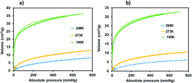 | ||
| Fig. 9 CO2 adsorption–desorption isotherms carried for JMS-1a (a) and Ru(II)@JMS-1a (b) (closed circles represent adsorption and open circles desorption). | ||
Carbon dioxide sorption studies of JMS-1a and Ru(II)@JMS-1a show a typical type 1 isotherms which suggests the microporosity nature of these materials (Fig. 9). JMS-1a has a volumetric uptake of 8.59 and 12.92 cm3 (STP) g−1 (0.384 and 0.576 mmol g−1) at 298 and 273 K respectively. The presence of Ru(II)p-cymene in Ru(II)@JMS-1a explains its reduced CO2 uptake of 6.08 and 10.42 cm3 (STP) g−1 (0.274 and 0.465 mmol g−1) at 298 and 273 K respectively. However, we noted that the amount of CO2 uptake by these material is comparable which is consistent with the structural modifications suggested by PXRD studies (Fig. 3). Cohen and co-workers found out that upon cyclometalation of the Zr based MOF with Ir complex, the amount of N2 uptake increased with increase in the Ir content relative to the unfunctionalised MOF.44 This was attributed to the framework flexibility although other mechanisms were not ruled out. At 195 K, the amount of CO2 uptake increases abruptly at low pressure range, with volumetric uptake more than doubling to 36.25 and 32.62 cm3 (STP) g−1 (1.61 and 1.46 mmol g−1) at an absolute pressure of 701 mmHg for JMS-1a and Ru(II)@JMS-1a respectively. This confirms inherent permanent porosity of the MOFs. Carbon dioxide isotherms at 273 and 298 K reveal isosteric heats of adsorption (Qst) in the range 32 to 38 kJ mol−1 at load values ranging from 0.1 to 0.38 mmol g−1 indicating moderate to strong interaction of CO2 with the MOFs. The observed CO2 uptake are comparable to other MOFs reported in literature.40,45–47
Catalysis
NMR analysis of the digested MOFs before was carried out to confirm that no DMF molecules in the MOF catalysts and the formate product observed in our reaction was not from the DMF molecules. Fig. S4† (a) to (c) shows the proton NMR of JMS-1a, [Ru(II)Cl2(p-cymene)]2 in chloroform and the functionalised MOF Ru(II)@JMS-1a. Coordination of the [Ru(II)Cl(p-cymene)] to the activated phase JMS-1a is evidenced by 2 doublets around 5.3 ppm and 5.5 ppm (b) which shifted downfield and split into 4 doublets (c). The methyl protons of the p-cymene around 2.8 ppm, 2.1 ppm and 1.2 ppm shifted upfield upon coordination of Ru to the MOF backbone. Further proof is given by the splitting of the aromatic protons of the MOF, region 7.5 to 9.5 ppm (c). The absence of a peak at around 8 ppm confirms the absence of DMF in both JMS-1a and Ru(II)@JMS-1a.The conversion of CO2 to formate using JMS-1a and Ru(II)@JMS-1a as catalysts was carried out as described in the experimental section. Table 2 shows the results that were obtained when JMS-1a and Ru(II)@JMS-1a were used as catalysts for the conversion of carbon dioxide to formate under heterogeneous conditions. The actual mass of the MOF used for catalysis is presented in Table S1.† The formate formed was detected and quantified using 1H NMR (example 1 and Fig. S5 in ESI† shows how the yield of the formate was calculated).
| Entry | Catalyst | Temp/°C | Ratio CO2/H2 | Catalyst load (μmol) | Base | Solvent | Formate (mmol) | Yield/% |
|---|---|---|---|---|---|---|---|---|
| a Time 24 h, amount of base 5 mmol. Yield based on 1H NMR analysis using acetone as an internal standard. The yield was calculated based on the conversion of 5 mmol added base. | ||||||||
| 1 | Ru(II)@JMS-1a | 90 | 1![[thin space (1/6-em)]](https://www.rsc.org/images/entities/char_2009.gif) : :![[thin space (1/6-em)]](https://www.rsc.org/images/entities/char_2009.gif) 3 3 |
15.6 | KOH | THF | — | 0 |
| 2 | Ru(II)@JMS-1a | 90 | 1![[thin space (1/6-em)]](https://www.rsc.org/images/entities/char_2009.gif) : :![[thin space (1/6-em)]](https://www.rsc.org/images/entities/char_2009.gif) 3 3 |
15.6 | KOH | Toluene | — | 0 |
| 3 | Ru(II)@JMS-1a | 90 | 1![[thin space (1/6-em)]](https://www.rsc.org/images/entities/char_2009.gif) : :![[thin space (1/6-em)]](https://www.rsc.org/images/entities/char_2009.gif) 3 3 |
15.6 | KOH | Ethanol | 2.07 | 41.4 |
| 4 | Ru(II)@JMS-1a | 90 | 1![[thin space (1/6-em)]](https://www.rsc.org/images/entities/char_2009.gif) : :![[thin space (1/6-em)]](https://www.rsc.org/images/entities/char_2009.gif) 3 3 |
15.6 | K2CO3 | Ethanol | 1.43 | 26.7 |
| 5 | Ru(II)@JMS-1a | 90 | 1![[thin space (1/6-em)]](https://www.rsc.org/images/entities/char_2009.gif) : :![[thin space (1/6-em)]](https://www.rsc.org/images/entities/char_2009.gif) 3 3 |
15.6 | NaHCO3 | Ethanol | 1.75 | 35.0 |
| 6 | Ru(II)@JMS-1a | 90 | 1![[thin space (1/6-em)]](https://www.rsc.org/images/entities/char_2009.gif) : :![[thin space (1/6-em)]](https://www.rsc.org/images/entities/char_2009.gif) 3 3 |
15.6 | Et3N | — | 0.27 | ≈5 |
| 7 | No catalyst | 90 | 1![[thin space (1/6-em)]](https://www.rsc.org/images/entities/char_2009.gif) : :![[thin space (1/6-em)]](https://www.rsc.org/images/entities/char_2009.gif) 3 3 |
15.6 | KOH | Ethanol | — | 0 |
| 8 | Ru(II)@JMS-1a | 90 | 1![[thin space (1/6-em)]](https://www.rsc.org/images/entities/char_2009.gif) : :![[thin space (1/6-em)]](https://www.rsc.org/images/entities/char_2009.gif) 3 3 |
15.6 | No base | Ethanol | — | 0 |
| 9 | Ru(II)@JMS-1a | 110 | 0![[thin space (1/6-em)]](https://www.rsc.org/images/entities/char_2009.gif) : :![[thin space (1/6-em)]](https://www.rsc.org/images/entities/char_2009.gif) 4 4 |
15.6 | KOH | Ethanol | — | 0 |
| 10 | Ru(II)@JMS-1a | 110 | 1![[thin space (1/6-em)]](https://www.rsc.org/images/entities/char_2009.gif) : :![[thin space (1/6-em)]](https://www.rsc.org/images/entities/char_2009.gif) 0 0 |
15.6 | KOH | Ethanol | — | 0 |
| 11 | Ru(II)@JMS-1a | 110 | 1![[thin space (1/6-em)]](https://www.rsc.org/images/entities/char_2009.gif) : :![[thin space (1/6-em)]](https://www.rsc.org/images/entities/char_2009.gif) 4 4 |
15.6 | KOH | Ethanol | 4.77 | 95 |
| 12 | Ru(II)@JMS-1a | 110 | 1![[thin space (1/6-em)]](https://www.rsc.org/images/entities/char_2009.gif) : :![[thin space (1/6-em)]](https://www.rsc.org/images/entities/char_2009.gif) 4 4 |
20.8 | KOH | Ethanol | 4.94 | 98.8 |
| 13 | JMS-1a | 110 | 1![[thin space (1/6-em)]](https://www.rsc.org/images/entities/char_2009.gif) : :![[thin space (1/6-em)]](https://www.rsc.org/images/entities/char_2009.gif) 4 4 |
15.6 | KOH | Ethanol | 3.10 | 62.0 |
| 14 | [RuCl2(p-cymene)]2 | 110 | 1![[thin space (1/6-em)]](https://www.rsc.org/images/entities/char_2009.gif) : :![[thin space (1/6-em)]](https://www.rsc.org/images/entities/char_2009.gif) 4 4 |
15.6 | KOH | Ethanol | 1.22 | 24 |
Entry 1 and 2 shows that the solvent plays an important role in the formation of the product. The effect of the base was evaluated (entry 1 to 6). The highest yield of 41.4% was obtained using KOH base (entry 3) compared to 26.7 and 35.0% for K2CO3 and NaHCO3 respectively. It has been reported that high basicity is required for the deprotonation of the proton from metal dihydride complex (intermediate), and this explains why a high yield was obtained in the presence of KOH.48 Notably, the neutral amine base triethylamine (entry 6), which has been frequently employed in CO2 hydrogenation gave less satisfying results. This is because the Et3N molecule is bulky and cannot access the metal-hydride site to deprotonate the proton and this restricts catalysis on the surface of the MOF. This is evidence that the [Ru(II)Cl(p-cymene)] complex in encapsulated inside the pores of the MOF. It was noted that in the absence of the solid catalyst (entry 7) and base (entry 8) no product was formed which confirms the importance of the catalyst and base in the reduction of CO2. Control experiments in the absence of CO2 and H2 was carried out to determine the source of carbon in the formate that was produced. Entry 9 and 10 shows that in the absence of the gases no product was formed confirming that DMF was not the source of formate. The activated phase JMS-1a's ability to convert CO2 was also evaluated, interestingly, 1H NMR studies revealed the formation of formate. However, we noted that under the same conditions the yield obtained using JMS-1a (62%, entry 13) was significantly lower than that of the functionalised material Ru(II)@JMS-1a (entry 11). Majority of reports presented in literature use Zr-based MOFs that are functionalised with either Pt16 or Ir15 and none of these report on the activity of the Zr centre towards conversion of CO2 to formate. However, we are aware of the catalytic activities of lanthanides metals reported in literature.45,49 Having this in mind, we soaked our reactors in acid for 24 h and repeated the experiments several times using JMS-1a as the solid catalyst. These repeated experiments gave formate as the catalytic product, this confirmed that the La(III) MOF act as a catalyst for reduction of CO2. As presented in Table 2, encapsulation of [Ru(II)Cl(p-cymene)] gave rise to a significant increase in the product yield of formate. The combination of two metals in a single catalyst does not only lower the energetic requirements to speed up the reaction between carbon dioxide and hydrogen, but may possibly be altering the reaction pathway, to produce more desired product.
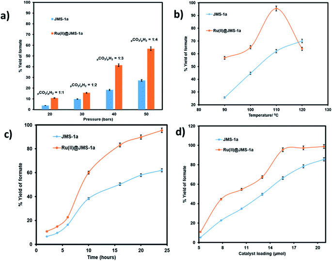
We evaluated the effect pressure, temperature, time and catalyst loading on the formation of the formate using the two catalysts (Fig. 10). Pressure variation was determined by changing the partial pressure of H2 while keeping the pressure of CO2 constant.
As illustrated in Fig. 10a an increase in the partial pressure of H2 results in an increase in the yield of formate produced by both JMS-1a and Ru(II)@JMS-1a catalysts. On increasing the pressure of H2 to 40 bars while keeping the CO2 pressure at 10 bars, the yield of formate produced increased up to 56% and 27.3% for Ru(II)@JMS-1a and JMS-1a respectively. This is attributed to the fact that sufficient partial pressure of H2 is required to generate the hydride and boost CO2 hydrogenation. The effect of temperature on the formation of formate was carried out at, 90 °C, 100 °C, 110 °C and 120 °C with other parameters being kept constant (Fig. 10b). We observed that the conversion of CO2 increases gradually with an increase in temperature reaching a yield of 95% at 110 °C for Ru(II)@JMS-1a. At 120 °C, a dramatic decrease in the yield of formate produced maybe be due to the decomposition of the formate species or the departure of the p-cymene molecule from the MOF backbone. Contrary to Ru(II)@JMS-1a which shows a dramatic decrease in the yield of formate produced at 120 °C, JMS-1a shows a gradual increase in yield of formate as temperature is increased although the yield of formate produced is lower than that of the functionalised MOF. Fig. 10c shows how the yield of formate produced varies with time. The yield increases with an increase in time to reach a yield of 94% and 62% for Ru(II)@JMS-1a and JMS-1a respectively. The effect of the catalyst load was also evaluated for both catalysts (Fig. 10d). In both cases, an increase in the catalyst load gave rise to an increase in the amount of formate produced which indicates that the formation of formate is 1st order with respect to the catalyst.50 When 18.2 μmol of Ru(II)@JMS-1a catalyst was used, 4.87 mmol of formate was produced which corresponds to 97% yield. The activated MOF JMS-1a produced 4.57 mmol of formate (91% yield) when 20.8 μmol of catalysts was used. The ruthenium precursor used for functionalization of the MOF was also employed in the conversion of CO2 to formate under optimised conditions. A yield of 24.3% formate was produced which is significantly lower than that of JMS-1a and Ru(II)@JMS-1a.
Poisoning studies were carried out using a wide range of different sized thiols to prove successful incorporation of the [Ru(II)Cl(p-cymene)] inside the pores of the MOF rather than on the surface (Fig. 11). Thiols are known to poison many transition metal catalysts. When bulky thiols benzylmercaptan and 8 mercapto-1-octanol were exposed to Ru(II)@JMS-1a the product yield was reduced by 16% and 24% respectively. In contrast, when Ru(II)@JMS-1a exposed to 2 mercapto-ethanol and 2 methyl-2-propanethiol, the yield was reduced by 56.6 and 52.2% respectively. Fig. S6–S9† shows the 1H NMR spectra of these studies. The absence of appreciable inhibition in the presence of the bulky thiols suggests that the most of the active species is encapsulated in the framework rather than bound to the surface. Notably, the most effective poisons are the least sterically demanding thiols (2 mercapto-ethanol and 2 methyl-2-propanethiol). This observation is consistent with bulk of the catalyst being encapsulated inside the MOF pores because the smaller thiols can easily access the catalytic sites by diffusion through the pores and poison the catalyst. Tsung and co-workers reported similar findings.51
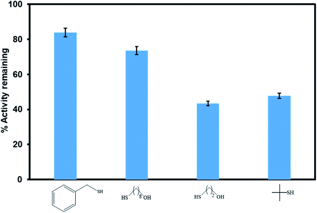 | ||
| Fig. 11 Comparison of the catalytic activity of Ru(II)@JMS-1a in the presence of different sized thiol poisons. | ||
Leaching, heterogeneity, and recycling studies
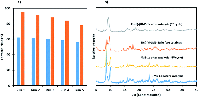
To investigate whether Ru(II)@JMS-1a and JMS-1a were actually working in a heterogeneous manner, the solid catalyst was filtered over a reaction duration of 6 h (for which a formate (1.14 mmol for Ru(II)@JMS-1a and 0.82 mmol for JMS-1a) was observed in the filtrate); the resulting colourless filtrate was used as the catalytic solution. Even after an extended period of time, no increase in formate was observed, whereas the original reaction produced a 4.8 and 3.10 mmol of formate for Ru(II)@JMS-1a and JMS-1a respectively after 24 h. This result suggests that the catalyst does not leach into the solution, and that the catalysts functions as a supported molecular catalyst. ICP-OES analysis of the aqueous solution in the reactor showed negligible metal leaching (0.0001% of La and <0.0001% of Ru for Ru(II)@JMS-1a and 0.0001% La for JMS-1a).To demonstrate recyclability of the prepared catalysts, their use over multiple runs was studied. For this, the hydrogenation was initially performed in a 5 mmol KOH solution at 110 °C under a total pressure of 50 bars for 24 h with a catalyst load of 20.8 μmol and 15.6 μmol for Ru(II)@JMS-1a and JMS-1a respectively. After the initial run, the catalysts were separated by filtration, washed thoroughly with ethanol and dried. The dried catalysts were then directly used for the next run with a fresh 5 mmol KOH solution. As shown in Fig. 12a, with JMS-1a, the yield of formate produced remained almost constant over the 5 runs. Contrary to this observation, Ru(II)@JMS-1a showed 17% decrease in the yield over five consecutive cycles although the yield obtained (78%) was still higher than that obtained using JMS-1a. PXRD studies Fig. 12b of the recycled catalyst after 5 cycles show that the structural integrity of JMS-1a is retained while that of Ru(II)@JMS-1a is slightly changed. Furthermore, the FTIR studies (Fig. S10†) before and after catalysis of the MOFs shows that the symmetric and asymmetric carboxylate stretches are located at similar positions. TGA analysis presented in Fig. S11† shows similar thermal profiles of the MOFs before and after catalysis.
Mechanisms
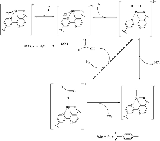
A large number of different reaction mechanisms have then been proposed for the metal-hydride reaction with either the hydrolyzed (HCO3−) or original CO2. They all have in common nucleophilic attack of the hydride ligand on the carbon atom in the substrate. This study does not contribute any new understanding of the mechanism(s) for the reduction of CO2 to formate at the La(III) sites and we refer the reader to the relevant literature.52 Both outer sphere,53 and inner sphere54 reactions of CO2/HCO3− have been proposed. The formation of formate at the Ru(II) sites is proposed as follows (Scheme 1), the first step involves reduction elimination of the Cl. This step provides open metal sites for the coordination of H2 molecules to give a dihydrogen complex [Ru(H2) (p-cymene)]. The active species, the ruthenium hydride RuH(p-cymene) is formed upon splitting of the coordinated H2 molecules with simultaneous elimination HCl. The insertion of CO2 via associative addition into the ruthenium hydride complex generates the formate complex which readily dissociates the formate.Conclusion
MOF JMS-1 has been successfully prepared and structurally characterised using spectroscopic and diffraction techniques. PXRD studies revealed a phase change induced by inclusion of the [Ru(II)Cl(p-cymene)] in JMS-1a. Hydrogenation of CO2 studies using the activated material (JMS-1a) and the functionalised MOF (Ru(II)@JMS-1a) revealed that both catalysts were able to convert CO2 to formate. However, the Ru(II) functionalised MOF produced high yields of formate in comparison to JMS-1a. Ru@JMS-1a performed better at temperatures below 110 °C while JMS-1a required harsh conditions to produce high yield of formate. Remarkably, JMS-1a can be easily recycled for five cycles without significant loss in the yield of formate while Ru(II)@JMS-1a shows a slight decrease in the yield of the product. This work is important as it present a new strategy of incorporating catalytically active centres in the MOF through cyclometalation. We have also demonstrated for the first time that La(III) MOF can be used for conversion of CO2 to formate. In future we expect to modulate the properties of the linker so that we can obtain a better yield of the product under less harsh conditions using La(III) MOFs.Conflicts of interest
There are no conflicts of interest to declare.Acknowledgements
The authors would like to thank the Green Chemistry for Life Program (PhosAgro/UNESCO/IUPAC), the Royal Society and the African Academy of Sciences for funding this project. Piwai Tshuma is grateful for the financial support she received from Organization for Women in Science for the Developing World. The University of Johannesburg Centre for Synthesis and Catalysis and Spectrum are appreciated for making their facilities available. We are grateful to Dr Clive Oliver of the University of Cape Town, Department of Chemistry for their assistance in gas sorption studies.References
- M. Rumayor and A. Dominguez-ramos, Appl. Sci., 2018, 8, 1–12 CrossRef.
- A. Dubey, L. Nencini, R. R. Fayzullin, C. Nervi and J. R. Khusnutdinova, ACS Catal., 2017, 7, 3864–3868 CrossRef CAS.
- G. H. Gunasekar, J. Shin, K.-D. Jung, K. Park and S. Yoon, ACS Catal., 2018, 8, 4346–4353 CrossRef CAS.
- F. Bertini, N. Gorgas, B. Stöger, M. Peruzzini, L. F. Veiros, K. Kirchner and L. Gonsalvi, ACS Catal., 2016, 6, 2889–2893 CrossRef CAS.
- S.-M. Lu, Z. Wang, J. Li, J. Xiao and C. Li, Green Chem., 2016, 18, 4553–4558 RSC.
- Q. Qian, M. Cui, Z. He, C. Wu, Q. Zhu, Z. Zhang, J. Ma, G. Yang, J. Zhang and B. Han, Chem. Sci., 2015, 6, 5685–5689 RSC.
- J. G. Vitillo, RSC Adv., 2015, 5, 36192–36239 RSC.
- J. C. Saint Remi, T. Rémy, V. Van Hunskerken, S. van de Perre, T. Duerinck, M. Maes, D. De Vos, E. Gobechiya, C. E. a Kirschhock, G. V Baron and J. F. M. Denayer, ChemSusChem, 2011, 4, 1074–1077 CrossRef PubMed.
- G. Nickerl, A. Henschel, R. Grünker, K. Gedrich and S. Kaskel, Chem. Ing. Tech., 2011, 83, 90–103 CrossRef CAS.
- G. Mehlana and S. A. Bourne, CrystEngComm, 2017, 19, 4238–4259 RSC.
- M. D. Allendorf and V. Stavila, CrystEngComm, 2015, 17, 229–246 RSC.
- I. Bratsos, C. Tampaxis, I. Spanopoulos, N. Demitri, G. Charalambopoulou, D. Vourloumis, T. A. Steriotis and P. N. Trikalitis, Inorg. Chem., 2018, 57, 7244–7251 CrossRef CAS PubMed.
- Y. Li and R. T. Yang, Am. Inst. Chem. Eng., 2008, 54, 269–279 CrossRef CAS.
- C. A. Trickett, A. Helal, B. A. Al-Maythalony, Z. H. Yamani, K. E. Cordova and O. M. Yaghi, Nat. Rev. Mater., 2017, 2, 17045 CrossRef CAS.
- B. An, L. Zeng, M. Jia, Z. Li, Z. Lin, Y. Song, Y. Zhou, J. Cheng, C. Wang and W. Lin, J. Am. Chem. Soc., 2017, 139, 17747–17750 CrossRef CAS PubMed.
- E. S. Gutterød, S. Øien-ØDegaard, K. Bossers, A. E. Nieuwelink, M. Manzoli, L. Braglia, A. Lazzarini, E. Borfecchia, S. Ahmadigoltapeh, B. Bouchevreau, B. T. Lønstad-Bleken, R. Henry, C. Lamberti, S. Bordiga, B. M. Weckhuysen, K. P. Lillerud and U. Olsbye, Ind. Eng. Chem. Res., 2017, 56, 13206–13218 CrossRef.
- B. An, J. Zhang, K. Cheng, P. Ji, C. Wang and W. Lin, J. Am. Chem. Soc., 2017, 139, 3834–3840 CrossRef CAS PubMed.
- J. Ye and J. K. Johnson, Catal. Sci. Technol., 2016, 6, 8392–8405 RSC.
- M. B. Chambers, X. Wang, N. Elgrishi, C. H. Hendon, A. Walsh, J. Bonnefoy, J. Canivet, E. A. Quadrelli, D. Farrusseng, C. Mellot-Draznieks and M. Fontecave, ChemSusChem, 2015, 8, 603–608 CrossRef CAS PubMed.
- H. Fei, M. D. Sampson, Y. Lee, C. P. Kubiak and S. M. Cohen, Inorg. Chem., 2015, 54, 6821–6828 CrossRef CAS PubMed.
- D. Sun, Y. Fu, W. Liu, L. Ye, D. Wang, L. Yang, X. Fu and Z. Li, Chem.–Eur. J., 2013, 19, 14279–14285 CrossRef CAS PubMed.
- S. S. M. Cohen, P. V Dau, M. Kim and S. M. Cohen, Chem. Sci., 2013, 4, 601–605 RSC.
- SAINT, version 7.60a, Bruker AXS Inc, Madison, Wi, USA, 2006 Search PubMed.
- G. M. Sheldrick, Acta Crystallogr., Sect. C: Struct. Chem., 2015, 71, 3–8 Search PubMed.
- (a) L. J. Barbour and J. Supramol, Chem, 2003, 1, 189–191 Search PubMed; (b) O. D. Friedrichs, SYSTERE 1.1.4beta, 2019, http://gavrog.sourceforge.net/ Search PubMed; (c) V. A. Blatov, TOPOS 4.0, Struct. Chem., 2012, 23, 955–963 CrossRef CAS; (d) M. O'Keeffe, M. A. Peskov, S. J. Ramsden and O. M. Yaghi, Accts. Chem. Res., 2008, 41, 1782–1789 CrossRef PubMed.
- B. Li, T. Roisnel, C. Darcel and P. H. Dixneuf, Dalton Trans., 2012, 41, 10934 RSC.
- A. L. Spek, Acta Crystallogr. Sect. D Biol. Crystallogr., 2009, 65, 148–155 CrossRef CAS PubMed.
- P. M. Forster, J. Eckert, B. D. Heiken, J. B. Parise, J. W. Yoon, S. H. Jhung, J.-S. Chang and A. K. Cheetham, J. Am. Chem. Soc., 2006, 128, 16846–16850 CrossRef CAS PubMed.
- L. Wen, P. Cheng and W. Lin, Chem. Sci., 2012, 2288–2292 RSC.
- S.-L. Yang, P.-P. Sun, Y.-Y. Yuan, C.-X. Zhang and Q.-L. Wang, CrystEngComm, 2018, 20, 3066–3073 RSC.
- J. Yuan, L. Mu, J. Li, L. Zhang, G. Li, Q. Huo and Y. Liu, CrystEngComm, 2018, 20, 2169–2174 RSC.
- A. Schoedel, M. Li, D. Li, M. O'Keeffe and O. M. Yaghi, Chem. Rev., 2016, 116, 12466–12535 CrossRef CAS.
- E. V. Alexandrov, V. A. Blatov, A. V. Kochetkov and D. M. Proserpio, CrystEngComm, 2011, 13, 3947–3958 RSC.
- N. W. Ockwig, O. Delgado-Friedrichs, M. O'Keeffe and O. M. Yaghi, Acc. Chem. Res., 2005, 38, 176–182 CrossRef CAS PubMed.
- A. K. Inge, M. Köppen, J. Su, M. Feyand, H. Xu, X. Zou, M. O'Keeffe and N. Stock, J. Am. Chem. Soc., 2016, 138, 1970–1976 CrossRef CAS PubMed.
- M. Li, D. Li, M. O. Kee and O. M. Yaghi, Chem. Rev., 2014, 114, 1343–1370 CrossRef CAS PubMed.
- N. L. Rosi, J. Kim, M. Eddaoudi, B. Chen, M. O. Keeffe and O. M. Yaghi, J. Am. Chem. Soc., 2005, 127, 1504–1518 CrossRef CAS PubMed.
- P. V Dau and S. M. Cohen, Chem. Commun., 2013, 6128–6130 RSC.
- M. Chen, D. Liu, Y. Deng, W. Fu, H. Zou, Z. Chen, C. Xia and F. Liang, Inorg. Chem. Commun., 2015, 55, 96–98 CrossRef CAS.
- N. Chatterjee and C. L. Oliver, Cryst. Growth Des., 2018, 18, 7570–7578 CrossRef CAS.
- D. C. Zhong, W. X. Zhang, F. L. Cao, L. Jiang and T. B. Lu, Chem. Commun., 2011, 47, 1204–1206 RSC.
- L. Wu, W. Wang, R. Liu, G. Wu and H. Chen, R. Soc. Open Sci., 2018, 5, 181378 CrossRef CAS PubMed.
- J. L. C. Rowsell and O. M. Yaghi, Angew. Chem. Int. Ed., 2005, 44, 4670–4679 CrossRef CAS PubMed.
- S. S. M. Cohen, P. V Dau, M. Kim and S. M. Cohen, Chem. Sci., 2013, 601–605 Search PubMed.
- B. Ugale, S. S. Dhankhar and C. M. Nagaraja, Cryst. Growth Des., 2018, 18, 2432–2440 CrossRef CAS.
- B. Ugale, S. S. Dhankhar and C. M. Nagaraja, Inorg. Chem., 2016, 55, 9757–9766 CrossRef CAS.
- H. T. D. Nguyen, Y. B. N. Tran, H. N. Nguyen, T. C. Nguyen, F. Gándara and P. T. K. Nguyen, Inorg. Chem., 2018, 57, 13772–13782 CrossRef CAS PubMed.
- P. Patel, S. Nandi, M. S. Maru, R. I. Kureshy and N. U. H. Khan, J. CO2 Util., 2018, 25, 310–314 CrossRef CAS.
- C. Pagis, M. Ferbinteanu, G. Rothenberg and S. Tanase, ACS Catal., 2016, 6, 6063–6072 CrossRef CAS.
- Y. Liao, Z. Cheng, W. Zuo, A. Thomas and C. F. J. Faul, ACS Appl. Mater. Interfaces, 2017, 9, 38390–38400 CrossRef CAS.
- Z. Li, T. M. Rayder, L. Luo and C. Tsung, J. Am. Chem. Soc., 2018, 140, 8082–8085 CrossRef CAS PubMed.
- A. M. Appel, J. E. Bercaw, A. B. Bocarsly, H. Dobbek, D. L. Dubois, M. Dupuis, J. G. Ferry, E. Fujita, R. Hille, P. J. A. Kenis, C. A. Kerfeld, R. H. Morris, C. H. F. Peden, A. R. Portis, S. W. Ragsdale, T. B. Rauchfuss, J. N. H. Reek, L. C. Seefeldt, R. K. Thauer and G. L. Waldrop, Chem. Commun., 2013, 6621–6658 CAS.
- J. E. Heimann, W. H. Bernskoetter and N. Hazari, J. Am. Chem. Soc., 2019, 141, 10520–10529 CrossRef CAS PubMed.
- C. Federsel, R. Jackstell, A. Boddien, G. Laurenczy and M. Beller, ChemSusChem, 2010, 3, 1048–1050 CrossRef CAS PubMed.
Footnote |
| † Electronic supplementary information (ESI) available. CCDC 1851044. For ESI and crystallographic data in CIF or other electronic format see DOI: 10.1039/c9ra09938g |
| This journal is © The Royal Society of Chemistry 2020 |


