
 Open Access Article
 This Open Access Article is licensed under a Creative Commons Attribution-Non Commercial 3.0 Unported Licence
Multivalent counterions induced attraction between DNA polyelectrolytes
Xu Chen,
Er-Qiang Chen and
Shuang Yang *
*
Beijing National Laboratory for Molecular Sciences, Key Laboratory of Polymer Chemistry and Physics of Ministry of Education, Center for Soft Mater Science and Engineering, College of Chemistry and Molecular Engineering, Peking University, Beijing 100871, China. E-mail: shuangyang@pku.edu.cn
First published on 9th January 2020
Abstract
In this paper we study the electrostatic attraction between two parallel rodlike DNA polyelectrolytes induced by neutralizing multivalent counterions at the zero temperature limit. The counterions crystallize on the charged surfaces of DNA so that we can handle the system by using the Wigner crystal lattice model. We derived the 3D ground state configuration of counterions with minimized energy by use of the gradient descent method, and calculated the interaction between two DNA cylinders with divalent or trivalent counterions when they approach. The results show that the complex ground state configuration of counterions plays a key role in determining the caused attraction. The counterions form three-dimensional Wigner crystals on each cylinder at large separation. When the cylinders are brought together, some counterion lines will move towards the inner region and lead to strong attraction. The calculated interaction from our model is in good agreement with the simulation result, however, the single particle approximation considerably overestimates the attraction.
1 Introduction
Electrostatic interactions play a fundamental role in determining the complex structure and dynamics of DNA molecules in aqueous solution due to their highly charged nature.1–5 The positively charged counterions experience strong electrostatic attractions to the backbone of the chains, and the Manning condensation of counterions on the surface of DNA should be taken into account.6 In the presence of monovalent cations, the force between DNA strands is repulsive. However, condensed multivalent ions may reverse the repulsion to attraction between DNA cylinders. This attraction is based solely on electrostatic interactions. A variety of experiments7–12 and computer simulations13–19 have observed attraction between like-charged cylindrical macroions in the presence of multivalent counterions. Quantitative determination of counterion mediated interactions is believed to be the key in understanding phenomena including DNA condensation and packaging inside viral capsids,3,20,21 and the formation of charged biopolymer bundles22 such as F-actin, microtubules and tobacco mosaic virus.23The electrostatic interactions between two objects can be well described using the mean-field Poisson–Boltzmann (PB) theory24 for monovalent counterions, which always predict repulsion between two parallel DNA cylinders due to the weak correlation between ions (the weak coupling regime). Based on the PB theory, quantities of work have been done to include the factors not considered. Modified Poisson–Boltzmann (MPB) theory can in part consider the interionic correlations.25 Besides, the ion hydration and polarization process are also of great importance, which is captured by the ε-MPB theory introduced by Gavryushov.26,27 However, the mean-field level description will break down if the correlation between ions becomes important.28,29 The importance of correlation effect of ions can be quantified by the defined coupling constant Ξ = 2πq3lB2σ ≫ 1,30 where the q, σ denote the valency of counterions, and the surface charge density of macroions, respectively. lB is the Bjerrum length given by lB = e2/4πεkBT, which denotes the distance at which two elementary charges interact with thermal energy kBT. ε = εrε0 is the dielectric constant with ε0 the vacuum permittivity and εr the relative dielectric constant (εr ≈ 80 for water). In the strong coupling limit (Ξ ≫ 0) counterions form strongly correlated layers, which may be the origin of the like-charged attraction.31
Amount of models have attempted to explain the origin of this attractive force between rodlike DNA polyelectrolyte.22 One mechanism is the covalence-like binding.32,33 Another one is that the attraction results from longitudinal counterion density fluctuations and correlations between condensed counterions, and the high temperature Gaussian approximation in 1D models can be used to calculate the force.13,32,34–39
On the other hand, Levin et al. pointed out that the structural correlations in positions of condensed counterions on the two cylinders is responsible for the attraction.2 This structural correlation mechanism works in strong-coupling (SC) limit of Ξ → ∞. In this case the energy of electrostatic repulsion between counterions confined at the DNA surface become sufficiently large, and the counterions may form quasicrystalline ordering, the so called Wigner crystals, which is the ground state configuration of the system at temperature T = 0.22 When brought two walls together, the counterions of two Wigner crystals on these two highly charged walls correlate themselves to minimize the electrostatic energy. Rouzina and Bloomfield applied the idea of counterions ordering to the problem of DNA condensation in terms of a modified calculation of forces between flat surfaces.40 The structure of 2D Wigner crystal in planar geometry41,42 as well as the attraction between two plates has been thoroughly studied at low43 or high temperatures.44,45 For DNA cylinders, when distance between them is small the condensed ions on the surface of cylinders arrange themselves in a staggered configuration.2,46–48 In this situation, counterions on one DNA cylinder will interlock with correlation holes (spaces between condensed counterions)49 on the other DNA cylinder and two cylinders attract each other.48
Furthermore, Netz et al. suggested a strong coupling mechanism of like-charge attraction and put forward an asymptotic SC theory for electrostatic correlations in highly coupled system.30,50,51 Their theory presents a systematic treatment of correlations in SC regime that employs a virial expansion in terms of 1/Ξ. The leading SC behavior comes from a single-particle contribution in the potential of charged wall by omitting the repulsive interaction between the counterions and other higher order many body effects. The single particle approximation are further employed to describe the attractive interaction between two like-charged cylinders.51–54 However, it was found that the validity of this approximation is restricted to rather thin cylinders.54
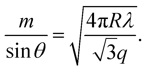
In order to predict the correct interaction between DNAs in the limit of Ξ → ∞ (or T = 0), the key issue is what the energy-minimizing arrangement of counterions is. Different from planar cases, the complexity of DNA system originates from the spatial curvature effect of cylinders, which means that a 3D structure of ground state must be considered.55 This ground state configuration of counterions around the cylinder is depended strongly on the size of cylinder and the valency of counterions.56,57 This effect can be quantitatively described by the geometric parameter γz = q/(λR), where the λ, R denotes the line charge density of cylinder and the radius of cylinder,58 respectively. Most of theoretical descriptions for two cylinders are usually under the assumption that γz is large enough, which means the reductive radius of the cylinders is rather small so that the cylinder can be treated as a needle.57 With this approximation, the ground state of counterion lattice can be simplified to 1D line model,37,59,60 or 2D coplanar model,58 to quantify the interaction between like-charged cylinders. Even for the less restricted 2D model, which believes that the ground state lattice of counterions can be seen as two coplanar lines on the inner side and outer side of cylinders, the result is only valid when γz > 1.5.58 However, for B-DNA, which usually has a radius of 10 Å and charge density of 0.59 e Å−1,22 the γz is 0.34 for divalent counterions and 0.51 for trivalent counterions, which means that an accurate description for DNA condensation must account for finite size effect of DNA.
To find the ground state configuration of two-DNA system is a formidable task because of the rather complicated possible arrangement. Even for the simplest case of two thin charged cylinders in contact, Arnold and Holm's calculation have shown that the ground state of counterion lattice form a quasi-crystalline flat pattern in the plane spanned by the two cylinders. For γz > 3.45 the counterions are lined up in the gap between two cylinders. Then for 1.175 < γz < 3.45 it is a 2D coplanar configuration, in which some part of counterions resides between two cylinders with interlocking pattern while others are located on the outer surfaces.58 For thick DNA cylinders with smaller γz, the ground state configuration of counterions is a complex deformed hexagonal Wigner lattice,55,61 which has never been rigorously analyzed. The difficulty of dealing with the interaction between DNA cylinders comes from the lack of precise description for the ground state lattices of thick cylinders. For an isolate cylinder with the shape and charge density similar to a DNA molecule, the ground state (T = 0) of counterions should be a 3D Wigner lattice22 and it is the starting point to investigate the interaction between cylinders at finite temperature. More importantly, when two DNA cylinders approach to each other, the cylinder Wigner lattice will be deformed in a complicated way. Solis and de la Cruz found that the multivalent counterions condensed to the cylinders exhibit a strong transversal polarization instead of on-plane configuration.56 Using Molecular Dynamic (MD) simulation, Kuron et al. and Deserno et al. found that when like-charged cylinders are close to each other, the counterions has a azimuthal distribution around each cylinder axis and they tend to concentrate in the intervening region of two cylinders.16,19 As the counterions in the intervening region are attracted by both two cylinders, they usually have lower electrostatic energy. Besides, when the helix strand structure of discrete cylinder charges is taken into account, the spatial distribution of counterions are more complex and leads to important corrections.53,62,63 Although these results highlights the azimuthal distribution of counterions at finite temperature, we believe that the deformation of 3D Wigner crystal structure at ground state is also crucial for the attractive interaction between charged cylinders, which has not yet been studied previously.
In this paper, we consider the attraction induced by bivalent or trivalent counterions between two parallel DNA cylinders by use of Wigner Crystal model corresponding to T = 0. It is probably a good approximation that the attractive force between DNAs arises from the structure of the ground state.31 Therefore, the Wigner crystal model provides the best way to estimate accurately the upper attraction energy due to counterion correlation. We focus on the precise ground state configurations of two DNA cylinders with multivalent counterions, and quantitatively calculate the attractive interaction between cylinders as the function of DNA distance for the first time. The organization of this paper is as follows. We introduce our model and give the calculation method of energy and force firstly in Section 2. Then in Section 3 we will analyze the complex 3D Wigner lattice structure of counterions for a single cylinder with low γz. Based on this result, the ground state configuration for two DNA cylinders will be further calculated by using gradient descent method. The electrostatic interaction and force between them are then obtained. We will further compare our calculation with that both using MD simulation and using the single particle approximation in SC theory. The results show that for DNA–DNA system, the deformed Wigner lattice is crucial to determine the attraction induced by multivalent counterions. We conclude in Section 4. Our goal is twofold. One is to provide a general model and calculation method for dealing with 3D ground state structure of counterions, and the other is to obtain the precise attraction due to electrostatic correlation for DNA systems. Therefore, our study may provides a deeper insight into the behavior of electrostatic interactions.
2 Models and methods
2.1 Models of DNAs and counterions
Our system consists of two DNA molecules (stiff polyelectrolytes chains) with counterions only. Each individual DNA molecule is modeled as a hard-core cylinder with negative charges.19,54,58 The two identical cylinders of radius R1 are parallel and oriented along the z-axis. Also they are infinitely long of length. The negative charges are assumed to be uniformly distributed on the surfaces of both cylinders. The counterions are modeled as positively charged hard spheres of radius R2. Since our target is to figure out the ground state configuration (strong coupling limit of Ξ → ∞ under T = 0) of counterions, we assume all counterions collapse on and contact with the charged surface, and the validity of this model has been proved by Šamaj et al.44,45 Note that the electrostatic properties of a uniformly charged sphere is equivalent to a charged point. For simplicity, in the following we will use R = R1 + R2 to equivalently substitute the radius of each cylinder and treat each counterion as a point charge, as shown in Fig. 1(a). Then the size effect of counterions is included in parameter R, which means increasing counterion radius will increase the effective radius of cylinder and thus slightly decrease the interaction between cylinders and counterions. This finite size effect might further cause uneven counterion distribution around the cylinder and then affect the interaction between cylinders in finite temperature,64 however, we will omit this effect in ground state system. Furthermore, we assume that the valency of charged counterions is +q and each DNA cylinder has a linear charge density of λ (in units of elementary charge). In terms of the overall electroneutrality condition, the number of counterions per unit length for each cylinder is λ/q. Namely, the average distance between two adjacent counterions in z direction is l0 = q/λ. The surface-to-surface distance of two cylinders is Δ (see Fig. 1(b)).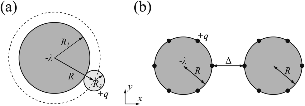 | ||
| Fig. 1 For the ground state with T = 0, all the counterions collapse on the DNA surface. (a) The DNA cylinder has radius of R1 and the counterion has radius of R2. The uniformly charged counterion (hard sphere) can be seen as a point charge and is located on the surface of an effective cylinder (represented by dash line) with radius of R = R1 + R2. (b) Schematic top view of the equivalent two-DNA system. The circles represent the effective cylinders and black dots represent the counterions. The surface-to-surface distance of two cylinders is represented by Δ. | ||
In this study, we aim at the calculation of DNA–DNA attractive interaction by use of Wigner crystal model. Although the real system is quite complicated,65 we will make some approximations here in order to isolate the Coulomb interaction and highlight the importance of counterion-correlation induced attraction. The van der Waals force, hydration force and the entropy of mobile counterions will be omitted because the electrostatic interaction is the origin of attraction in DNA condensation. Also we ignore the dielectric inhomogeneity effect and set the relative dielectric constant to εr ≈ 80 for simplification, although in real DNA system the dielectric constant of water is far larger than the hydrocarbon.54
2.2 The ground state for a single DNA cylinder
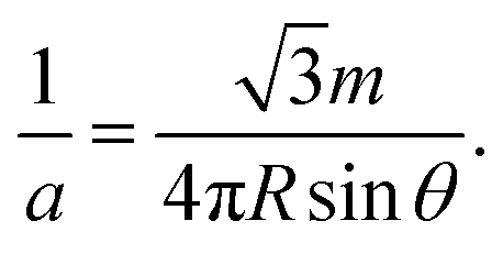
Before handling two cylinder system, we consider one single cylinder firstly and give a simple argument about the characteristic of counterions' ground state configuration. If the charged cylinder is thin enough or the charge density is low, so that the average lateral distance between counterions l0 = q/λ satisfies l0 ≫ R and the separation in z-axis of counterions is dominant. The counterions will be evenly distributed on both sides of cylinder cross section of y = 0 to minimize the repulsion between counterions. The adjacent counterions also try to keep away from each other, which leads to a zig-zag configuration of ions in x–z plane with y = 0 as depicted in Fig. 2(a). In this situation, the distance a between one ion and its nearest neighboring ion is given by
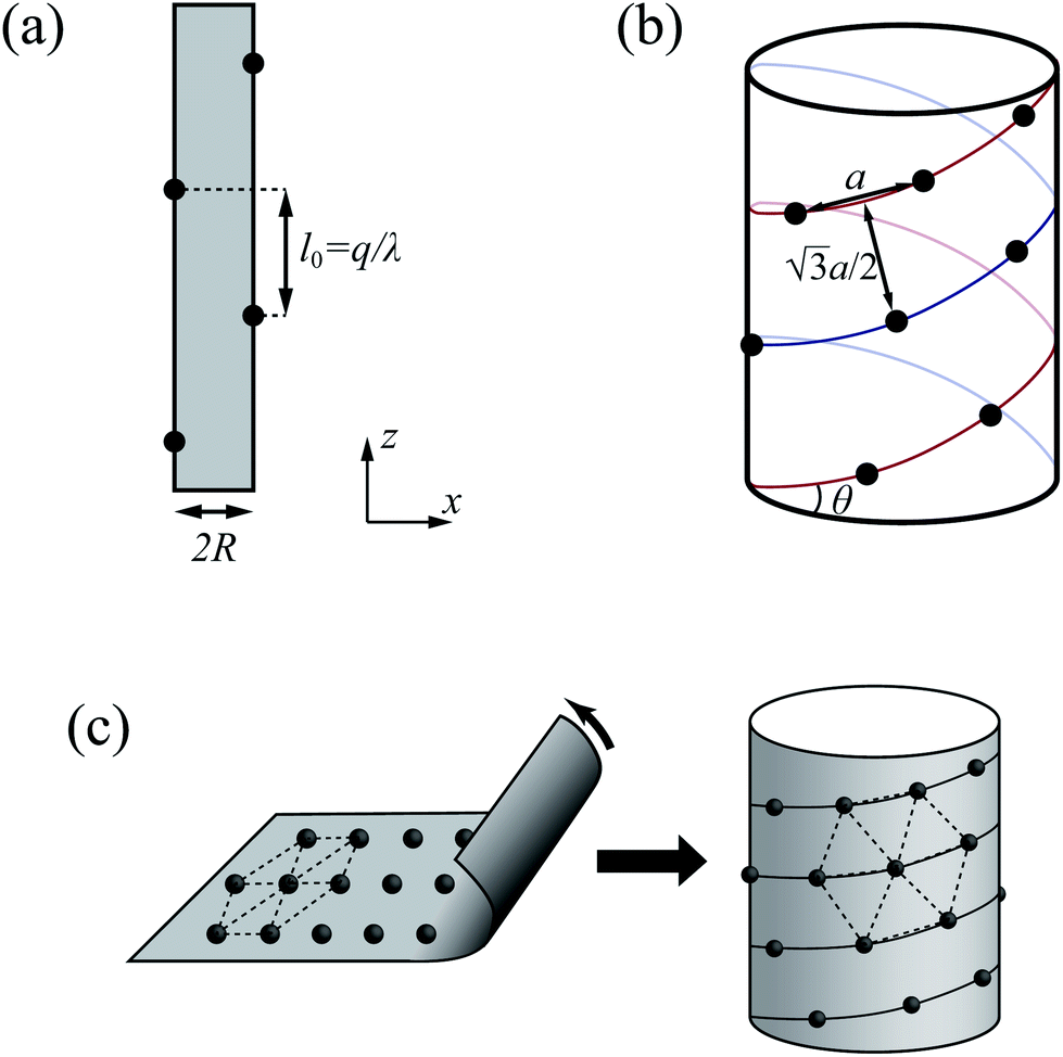 | ||
Fig. 2 (a) Schematic representation of the ground state in thin cylinder limit. The distance of adjoining counterions in z direction q/λ should be larger than the diameter of the cylinder 2R. (b) Schematic representation of cylinder Wigner structure. The distance between one ion and its nearest ions is represented by a, the vertical distance of two adjacent helix lines is 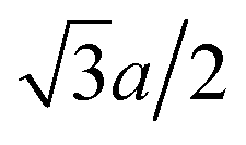 to fulfill the hexagonal structure. The helix angle is represented by θ here. (c) The formation of cylinder Wigner structure. The hexagonal lattice marked with dash lines can be seen in either plane or cylinder structure. The basic unit of cylinder Wigner crystal is the helix marked with solid lines. to fulfill the hexagonal structure. The helix angle is represented by θ here. (c) The formation of cylinder Wigner structure. The hexagonal lattice marked with dash lines can be seen in either plane or cylinder structure. The basic unit of cylinder Wigner crystal is the helix marked with solid lines. | ||
In order to preserve the stability of that zig-zag configuration, the distance between two neighboring ions on the same side may be not smaller than R, i.e. 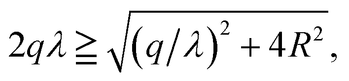 which means
 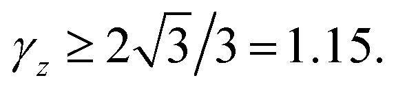 Once γz < 1.15, the z direction separation will not be the leading factor of spacing between adjoining ions. This structure may break down and more complex ground state will be formed. For two parallel thin cylinders, the counterions will form a two-dimensional coplanar configurations with interlocking patterns along the inner and outer sides as we mentioned previously, which has been thoroughly studied by Arnold and Holm.58
With the increase of cylinder radius, the curvature will decrease and the surface tends to be like a plane. For a DNA-like cylinder, the ground state of counterion lattice will resemble 2D hexagonal Wigner lattice structure on this surface rather than the zig-zag lattice.57 The ground state configuration of cylinder Wigner structure is shown in Fig. 2(b), which can be seen as rolling of plane Wigner crystal structure as depicted in Fig. 2(c). Here, the basic pattern of the cylinder Wigner crystal is the circular helix consisting of close packing ions, which has also been verified in previous simulation study.55 As the basic composition of this structure is the helices, we assume that there are m close packing helical counterion lines and the helix angle of each line is θ. The lattice can be seen as hexagonal structure in a plane so that each ion has 6 nearby ions at distance a. With this arrangement, we can derive that the vertical distance between two nearby helix lines or nearby loops is  as shown in Fig. 2(b). Combining with these parameters and the electroneutrality condition, the geometry of ground state lattice of counterions can be determined.
For each helix line per round, it moves 2πR![[thin space (1/6-em)]](https://www.rsc.org/images/entities/char_2009.gif) tanθ in z-direction (the helix pitch). So in the normal direction of helix lines it moves 2πRtanθ × cosθ = 2πRsinθ. At the same time, the distance in this direction should also be equal to
tanθ in z-direction (the helix pitch). So in the normal direction of helix lines it moves 2πRtanθ × cosθ = 2πRsinθ. At the same time, the distance in this direction should also be equal to 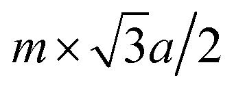 (m is an integer), that is to say, it is the m times of the hexagonal lattice spacing. Then we have one relationship
 | (1) |
For each counterion located in the lattice, it occupies the area of  and has charge of q, leading to the surface charge density of
  Meanwhile, the value should be equal to the surface charge density of the cylinder ρ = λ/2πR according to the electroneutrality condition,
 | (2) |
 | (3) |
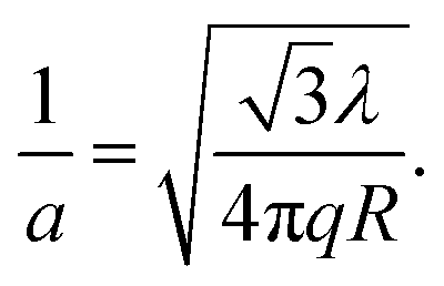
The lattice parameter a can further be calculated with eqn (2). Then θ can be calculated with a given number of helix lines m, and the position of each ion can be obtained.
All the above equations are valid based on the assumption that the cylinder surface curvature is small enough that it can be regarded as a plane. Apparently, this assumption will deviate from the reality with the decreasing of cylinder radius (i.e., the increasing of γz). To satisfy the assumption, the distance between nearby ions a should be shorter than the diameter of cylinder. As a crude estimation we conclude 
2.3 The grand state structures of two DNA cylinders
Now we consider two DNA cylinders system with low γz value. We need to determine the stable ground state configuration of counterions on each separation. However, to get a precise lattice structure is a tough task. In this section, we use the periodicity on z-direction and assume that the lattice of counterions is idealized to counterion lines, which will simplify the problem significantly. All the counterions attached to a cylinder is assumed to be on a finite number of counterion lines that parallel to the z-axis, as depicted with Fig. 3(a). Firstly, all the counterion lines are assumed to have the same line charge density of q/l0. We note that here l0 is a parameter representing the lateral distance along z-axis between two adjacent counterions on each line, and it is related to the linear charge density λ. In fact this approximation does not bring much deviation to the final result, which will be discussed later in Section 3.4. For each line, the counterion lattice of neighboring lines is relatively shifted in z-direction. The parallel lines form an inter-locking pattern to ensure the minimized repulsion between counterions. The total number of counterion lines should be suitable to make sure that the counterions lattice is close to the hexagonal Wigner structure in order to minimize the total energy. In this section, we set the cylinders to have a line charge density of 0.59 e Å−1 and radius of 10 Å, neutralized by +2 ions, which mimics B-DNA molecules neutralized by +2 ions. In this case, the lattice fits the hexagonal lattice very well if the number of counterions lines equals to 8.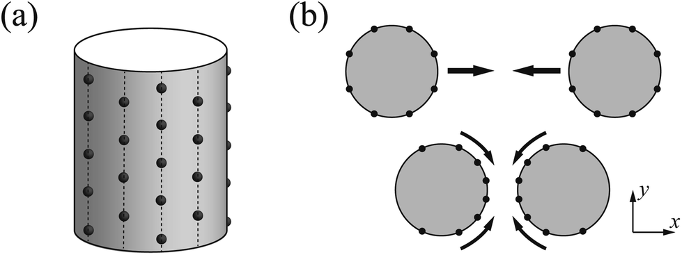 | ||
| Fig. 3 (a) All counterions are assumed to be on the lines parallel to the cylinder axis, and all the counterion lines on the cylinder surface are assumed to have the same line charge density. (b) The counterion lines have a tendency to move close to the intervening region between two cylinders when the cylinders are approaching. | ||
When the two cylinders approach, the counterions attached on cylinder surface tend to condense in the intervening region between two cylinders attributing to the strong attraction from another cylinder. Here, we abstract this process into the movement of counterion lines, as depicted in Fig. 3(b). The line charge density of each counterion line keeps constant during the movement, whereas the Wigner lattice will be deformed. For the sake of convenience for two cylinder system (Fig. 1(b)), we set that the z-axis of coordinate is the axis of cylinder 1 and the x-axis across the cores of two cylinders. The core of cylinder 1 is centered at the origin, and the core of cylinders 2 is at the point (Δ + 2R, 0, 0).
In order to determine the equilibrium azimuthal distribution of counterion lines, we investigate how the counterions on one cylinder affect the electrostatic potential on the surface of another cylinder. We calculated the electrostatic potential on cylinder 1 as a function of the position (denoted as azimuthal angle ϕ) under the effect of cylinder 2 without or with uniformly attached counterions. This potential for cylinder 2 with counterions is of course z-dependent and we choose the z position with lowest energy. Here we only give a typical example. The electrostatic potential Φ at the point ϕ = 0 (that is the closest one to the surface of cylinder 2) is set as zero point of potential on the surface of cylinder 1. The potentials for two different cases without or with counterions on cylinder 2 are depicted in Fig. 4(a) and (b), respectively. For both situations, the potential near the inner side is lower than that of the outer side, indicating the attraction from both cylinders. However, the dependence of circular potential gradient on position ϕ is different. Compared with the pure charged cylinder Fig. 4(a), the counterions on cylinder 2 will decrease the potential considerably. Besides, a plateau of potential can be seen when ϕ is between 60° and 300° as shown in Fig. 4(b). More importantly, the potential decreases rapidly with increasing the separation if the counterions exist on cylinder 2. This phenomenon may originate from the overall neutralization effect of cylinder and counterions. When cylinder 1 is far away from cylinder 2, the detailed counterions lattice structure will have tiny influence on the potential. The electrostatic interaction from counterions almost compensate on that from pure charged cylinder 2 due to the electroneutrality condition. Therefore, it is believed that the counterion lines will concentrate on the intervening region of cylinders only when they are close enough, but this deformation is quite short-ranged.
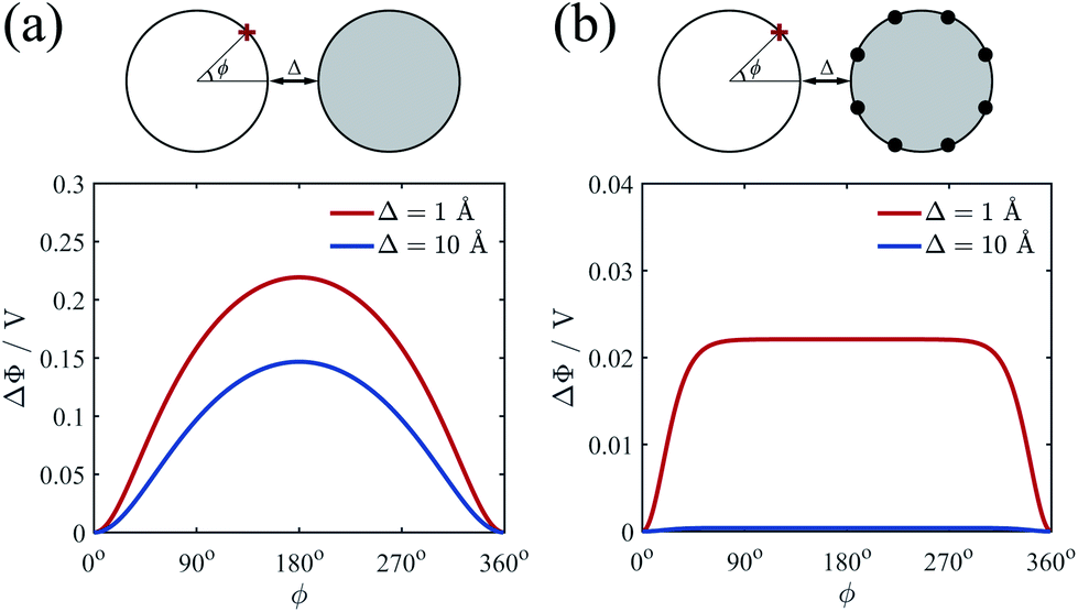 | ||
| Fig. 4 Electrostatic potential curves Φ on cylinder 1 produced by the field of cylinder 2 as a function of position ϕ. (a) The cylinder 2 has uniform distributed charges without counterions. (b) The charged cylinder 2 has collapsed counterions on its surface. The red ‘+’ represents the position with the angle of ϕ and V is the unit volt. Two different surface-to-surface distances Δ = 1 Å (red lines) and Δ = 10 Å (blue lines) are considered. | ||
Next, we will investigate how the lattice deform when two cylinders approach. For some counterion line i of cylinder 1, its total electric energy per unit length can be written as
 | (4) |
 | (5) |
The interaction energy per unit length between any two lines can be generally written as
 | (6) |
The interaction between lines i and j (i ≠ j) on the same cylinder can be written as
 | (7) |
 | (8) |
Here ϕα is the azimuthal angle of line α on another cylinder. For convenience, we choose ϕ variable for cylinder 2 has opposite direction to cylinder 1, so that ϕ2 = 0 correspond to the direction toward cylinder 1. Then the total energy per unit length related to counterions is the energy summation over all the 2n counterion lines as
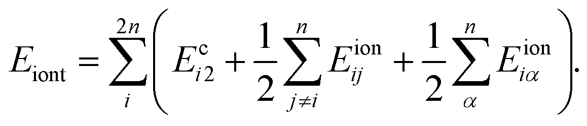 | (9) |
In above formula the prefactor 1/2 accounts for the double count of the interactions between different lines. For a given Δ, the repulsive energy between bare cylinders is a constant, the minimal energy of the whole system, as well as the equilibrium distribution of counterion lines, will be reached when Eiont is minimized. So, for every i we have
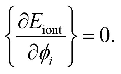 | (10) |
The deduced a set of nonlinear equations can be solved by the gradient descent method. Gradient descent is a commonly used first-order iterative optimization algorithm for finding the extrema of a function, which is realized by updating the parameters {ϕi} in the opposite direction of the gradient of total energy function, i.e. ∇ϕEiont. Here different extremum may probably be reached depending on the initial guess of azimuthal angles {ϕi}. In order to search for the real minima as well as possible, a sets of initial inputs of {ϕi} is given stochastically. After iteration calculation, we found all of them converge to one (or two/three at most) solution of configuration. Thus the minimal energy is picked up to be the true ground state energy 
2.4 The calculation of energy and force
The total energy of the system containing counterions of Wigner crystal lattice can be written as
 | (11) |
We will calculate the energy per unit length considering the periodicity in z-axis. The force per unit length between two cylinders thus can be further calculated with
Because the counterions tend to condense in the intervening region between two cylinders, their relative positions in each cylinder will not be fixed when the two cylinders are approaching. For a given separation Δ0, one have to find out the right arrangement of counterions on the surfaces with minimum energy E. To get the force between cylinders at Δ0, an increment in separation dΔ should be applied. Then the total energy at distance Δ0 and Δ0 + dΔ should be minimized respectively by finding out the two ground states configurations of counterions, and then the force can be calculated with FΔ0 = (EΔ0+dΔ − EΔ0)/LdΔ.
3 Results and discussions
3.1 Counterion line approximation for thin cylinder case
We firstly verify the validity of counterion line approximation for the thin cylinder case, which has been well studied. In this section, we assume that the cylinders have a line charge density of 0.59 e Å−1 and the radius of 1 Å, neutralized by +2 ions. The geometric parameter γz of this cylinder equals to 3.4, and thus the ground state configuration of counterions for single cylinder should be the zig-zag form as Fig. 2(a) shows. Here we assume that counterions on each cylinder will form two counterion lines, and the position of these lines is adjustable to minimize the total electrostatic energy. The relative position of the ions in z-direction is also variable and we assume the ions on different lines begin at different z-direction to get the minimal energy.We calculated the ground state energy as functions of the surface-to-surface distance Δ and then the force between these cylinders, which is depicted in Fig. 5(a). It can be found that the electrostatic force between cylinders is always attractive, and the sections of the force diagram is due to the changing of counterion configuration. The position of counterion lines is variable with the changing of Δ and Fig. 5(b) shows some characteristic configuration of counterion lines. Firstly, the counterions is all concentrated in the intervening region of two cylinders because of electrostatic attraction. Then, with the increasing of Δ and decreasing of the attraction, counterions begin to distribute either in the intervening region or the outside of two cylinders. This process is also proposed by Arnold et al.58 Finally, with the further increasing of Δ, the counterions will shows a bias distribution, which is also been observed by Solis et al.56 Thus we show the validity of the counterion line approximation and then expand it to DNA-cylinder case.
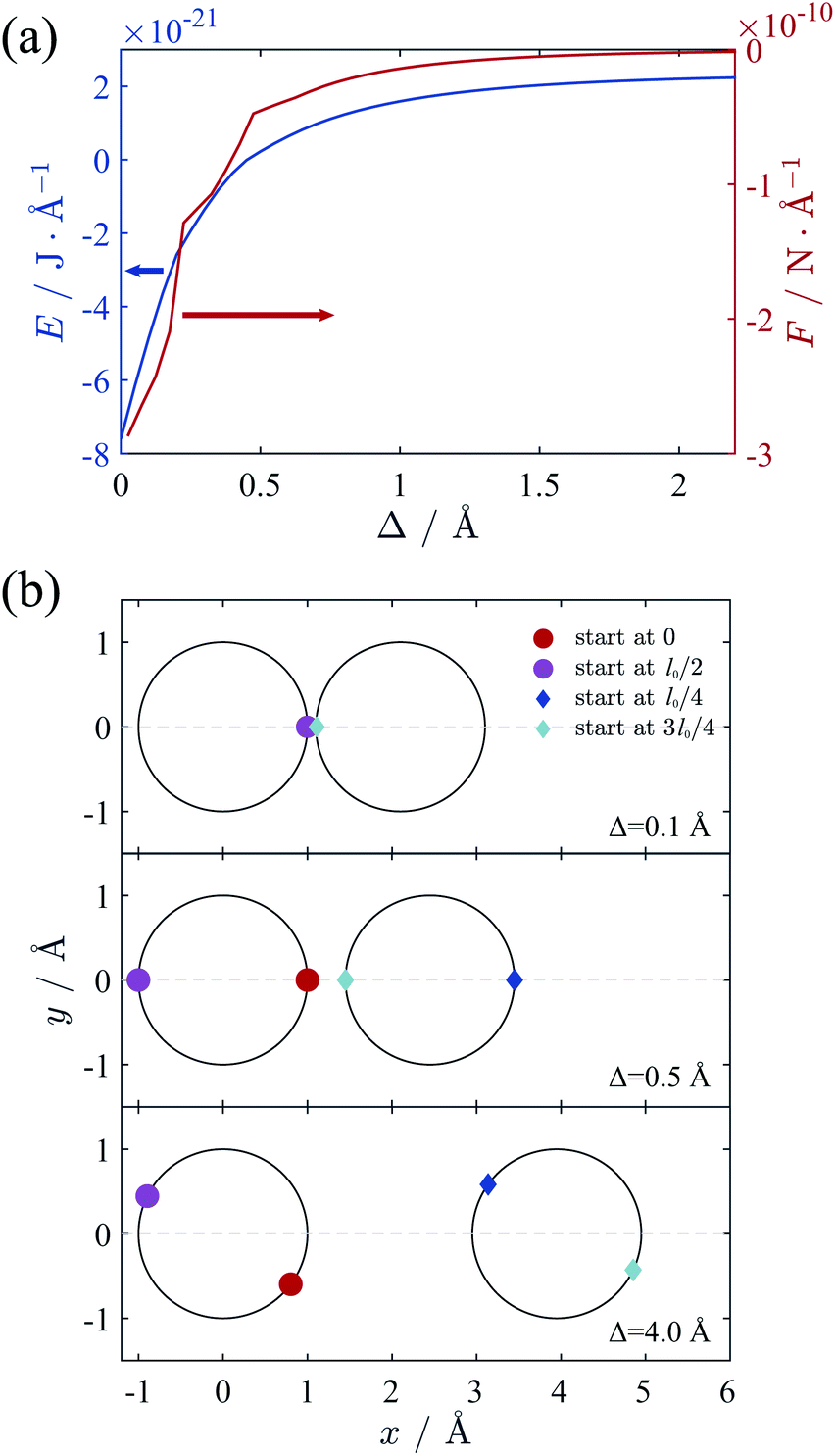 | ||
| Fig. 5 (a) Total energy and force between two cylinders as functions of separation Δ. λ is 0.59 e Å−1 and R is 1 Å, neutralized by +2 ions. (b) Some characteristic configurations of counterion lines during the changing of Δ from top view. The ions on different lines has different starting point in z-direction as the figure shows, where the l0 denotes the distance between two ions on each ion lines. | ||
3.2 The divalent counterions case
We firstly investigated the lattice of counterions of ground state at different separation Δ. Here we assume that the cylinders have λ of 0.59 e Å−1 and R of 10 Å, neutralized by +2 ions, which mimics B-DNA system. The counterion lines on a single cylinder surface tend to form a hexagonal structure as we mentioned before. However, the relative location of ion lines of two cylinders on z-direction is adjustable, which needs to be determined in terms of eqn (10). We assume the relative position of these lines in z-direction can take either one from two types of configuration shown in Fig. 6. The first one ensures all the ions far from each other in z-direction, as depicted in Fig. 6(a), and the second one only make sure that the ions on the two intervening lines are far from each other, as depicted in Fig. 6(b). After comparing the total energy for type 1 and type 2, we found that the system adopts type 1 configuration when the cylinders are close enough whereas type 2 will be dominant when the surface-to-surface distance is large. The transition point of this two configurations will be discussed later. Fig. 6 also gives the detailed ground state lattice of counterions. When Δ is small, part of the counterion lines move near to the intervening region, which agrees well with the circular potential gradient appearing at short separation we described previously. The previous simulation result also displayed the similar weak concentration of counterions in thick cylinder system although the system was studied at limit temperature.16 When Δ is large, all ion lines distribute almost uniformly around the cylinders, originating from the rapid decreasing of the potential gradient at large surface-to-surface distance. The two lines in the inner part having closest distance adopt the interlocking configuration to decrease the repulsion between counterions.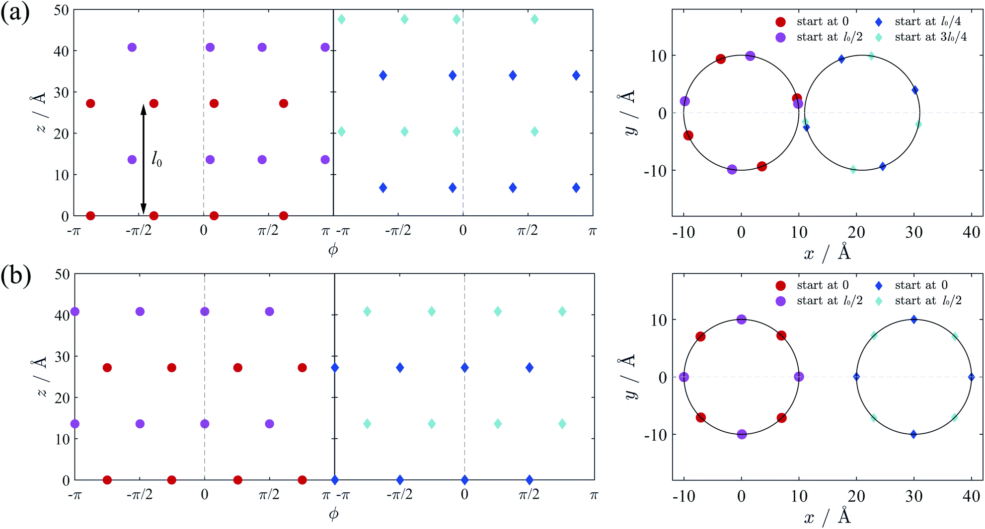 | ||
| Fig. 6 Two types of 3D configuration of counterions on different cylinders from side view and top view. (a) Type 1: the counterion lines tend to adopt the first configure, and part of cylinders tend to move to the intervening region. It occurs when the two cylinders are close (here Δ = 1 Å). (b) Type 2: all the counterion lines tend to evenly distribute and the two lines in the inner part with closest distance adopt the interlocking configuration. It occurs when the two cylinders are far away (here Δ = 10 Å). Different colored symbols have different positions of counterion lines on z direction. For cylinder 1, alternating counterion lines have z coordinates starting at 0 and l0/2, respectively. For cylinder 2, alternating counterion lines have z coordinates starting at l0/4 and 3l0/4. Also, the positions with azimuthal variable ϕ = 0 for cylinder 1 and 2 have closest distance Δ. | ||
With the above method, we calculated the ground state energy as functions of the surface-to-surface distance Δ at different numbers of counterion lines n. Then the force between cylinders can be calculated with adding the repulsive interaction between two pure charged cylinders to eqn (9). The results are depicted in Fig. 7. From Fig. 7(a) we found that the case of n = 8 always has minimal energy and there is a transition point for configuration of counterions at around 5.1 Å. With solved ground state the attractive force between cylinders can be calculated, as shown in Fig. 7(b). Interestingly, the force shows an abrupt jump due to the existence of the transition point, which means a sudden decreasing of force liking a first order phase transition.
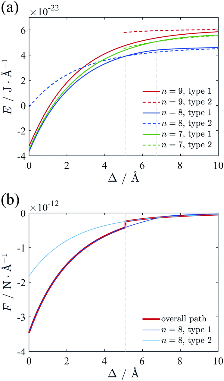 | ||
| Fig. 7 (a) Total energy of two-cylinder system as functions of separation Δ at different line number n. λ is 0.59 e Å−1 and R is 10 Å, neutralized by +2 ions. The lattice of n = 8 has the minimal energy, and the transition point of two configurations occurs at Δ = 5.1 Å. (b) Force between two cylinders derived from the energy of n = 8. Actual force is represented with red line, and an abrupt jump can be seen due to the crossing of the energy–distance curves. | ||
3.3 The trivalent counterions case
We also calculated the energy and force with the trivalent counterions. The total electrostatic energy and force are depicted in Fig. 8. For +3 counterions, the optimal configuration of counterion lattice with minimal energy corresponds to n = 6, which is also close to the hexagonal Wigner lattice at large separation. The force curve (Fig. 8(b)) shows a similar shape with the divalent system but with a stronger attraction and a transition point at lower separation. In Fig. 8(c) we compare the force (red curve) we calculated using the counterion line approximation with the experimental result11 (green square) and the simulation result19 (black circles) and at room temperature. The experimental attraction is slightly higher than our theory, however, it still shows a good fitting with our result. The simulation result shows a repulsion between cylinders when Δ is small. This repulsion can be attributed to the entropy of ions in finite temperature or the hydration force due to reconfiguration of water. We have omitted the hydration force in our theory because the attraction leading to DNA condensation originate from the electrostatic interaction.66 It can be seen that our result on ground state fits the simulation very well when Δ is large enough. The hydration force has a characteristic distance of 2.5–3.5 Å,20 which means that at larger separation distance, the hydration force and the short-ranged entropic contribution is weaken, showing that the finite temperature modification effect is possibly minor to the long range attractive force induced by trivalent counterions correlations.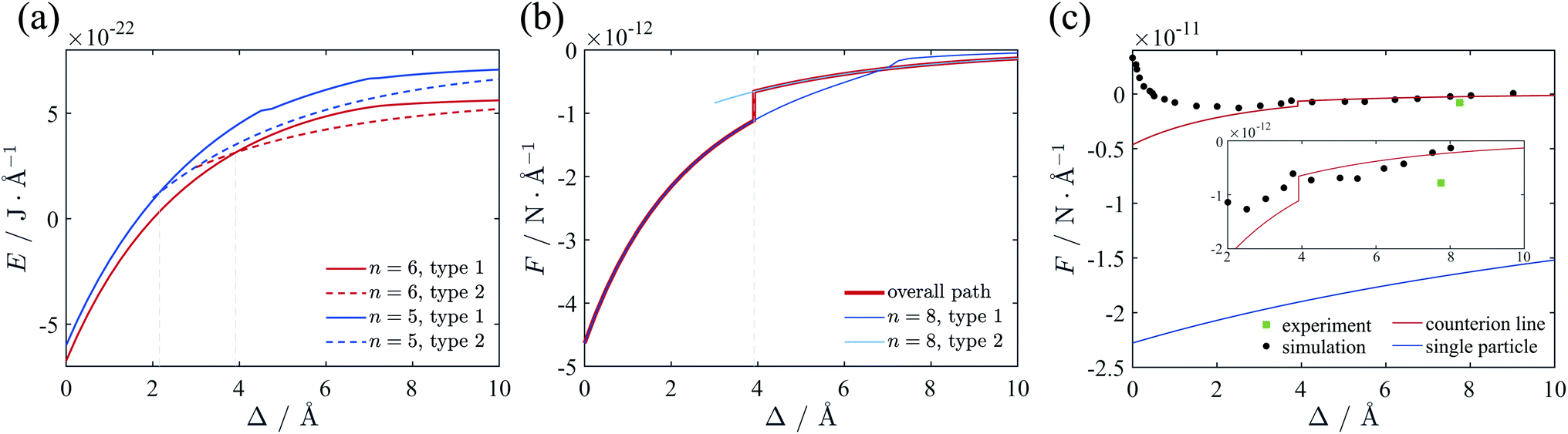 | ||
| Fig. 8 (a) Total energy of the two-cylinder system neutralized by trivalent counterions. The minimal energy is always with n = 6, and the transition point of two configurations is Δ = 3.9 Å. (b) Force between two cylinders. Actual force is represented with red line, and an abrupt change can be identified. (c) Comparison of the force derived from the different methods. The counterion line approximation fits well with the simulation results19 and the experimental result11 at large distance. The single particle approximation54 greatly deviates from the simulation result. | ||
As mentioned in introduction part, at strong coupling limit one can use the single particle approximation, in which case only the contributions from the interaction of individual counterions with charged cylinders are considered.54 For like-charged plates, the approximation may work well when both the correlation between counterions is strong and the surface separation is smaller than the lateral distance between ions.67 Here, we apply the single particle approximation to our cylinder system, and compare it with our calculation and the simulation result. In terms of the approximation the SC force per unit length can be obtained as54
 | (12) |
The result using single particle approximation is depicted in Fig. 8(c) with blue line. It can be seen that the single particle approximation considerably overestimate the attraction force. The validation of single particle approximation requires strong correlation and short separation limit. The strong correlation condition is satisfied in the zero temperature situation, where Ξ → ∞. However, the small separation condition is hard to achieve as the counterions can move around the cylinder surface. In Kanduč et al.'s work, these conditions are satisfied when Δ is small enough and all counterions distribute in the inner region of the cylinder.54 However, the approximation of concentrated counterions on intervening region is only valid for γz > 4.2, which corresponds to quite thin cylinders. All counterions tend to distribute in the intervening region of two cylinders. In this case the distance between counterions and cylinders is much smaller than the averaged lateral distance between counterions, and the single particle approximation can be applied. As we mentioned before, when cylinder size increases, the ground state lattice of counterions is not two ion lines in the inner side, but a hexagonal Wigner lattice with slight deformation. This variation of the lattice is due to the rapid reduction of attraction between one cylinder and the counterions on the other cylinder for large cylinder size, and the repulsion between counterions tend to form a hexagonal lattice. In other words, the counterions in thick cylinder system distribute more evenly around the cylinders while in thin cylinders they are denser in the intervening region. This phenomenon has been observed in simulation,16 where the counterion distribution around the thinner cylinder shows a sharper azimuthal distribution function at finite temperature. For DNA we find that γz = 0.51 or 0.34 when attached by +3 or +2 counterions, respectively, which is beyond the range of thin cylinder assumption. Therefore, the single particle approximation beaks out for DNA-like thick cylinder system. Consequently, our method can theoretically handle thick cylinders, which is an important complementary to the single particle approximation.
3.4 The case with different line charge density
The results above are under the assumption that each counterion line has the same line charge density λr. However, this assumption may deviate from the real energy-minimizing configurations due to the deformation of lattice for small surface-to-surface distance of cylinders. In this section, we will release this assumption and investigate how the final force will be affected. Before the calculation, we note that the electric potential in Fig. 4(b) shows the rapidly reduced potential gradient as the ϕ increasing. Hence the accumulation of counterions will mainly happen in the intervening region of cylinders. Furthermore, Fig. 6(a) shows that even for very closed cylinders only part of lines are attracted to the inner side, while other lines are not affected significantly. So we assume that only one counterion line on each cylinder near the intervening region has higher line charge density λinr than other lines λoutr to represent the accumulation effect of counterions. In this section the system is the same as Section 2.3 and the cylinders are neutralized by divalent counterions. The positions of counterion lines are all free to move around the surface of cylinders. For a given separation, we calculated the ground state energies with different line charge density ratio λinr/λoutr varying from 1 to 3, and then choose the ratio with minimal energy as equilibrium value.Fig. 9(a) gives the ground state configuration of counterion lines when the two cylinders are very close (Δ = 1 Å), in which case the optimal ratio is λinr/λoutr = 1.8. All the lines on each cylinder are close to evenly distribute, but the space between the line of ϕ = 0 with higher charge density and its adjacent lines is larger than others, resulting from the stronger repulsion of higher λinr. Compared with the case of uniform line charge density (λinr/λoutr = 1), the two lines with higher λr are located on the opposing surfaces of ϕ = 0 and form an inter-locking pattern, rather than the configuration with a little azimuthal bias as Fig. 6(a). With the ground state configuration and energy, the calculated force between cylinders is depicted as red dots in Fig. 9(b). It should be noticed that the force calculated with variable λr quite agrees with the result in Section 2.3 (black curve in Fig. 9(b)), which is derived from the equal charge density assumption for all counterion lines. At small distance, the minimizing energy ratio between the value from the black curve to the red dots is a little larger than 1. With increasing Δ, the ratio approaches to 1 gradually. Despite the complexity of counterion configuration, our result indicates that the uniform counterion-line charge density assumption in Section 2.3 indeed gives rather accurate prediction. Therefore, we believe that our method of calculating the interaction between cylinders in Section 2.3 is applicable to the accumulation effect of counterions between two cylinders.
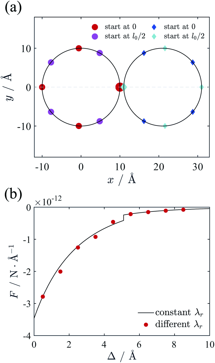 | ||
| Fig. 9 (a) Top view of the configuration of counterion lines when Δ = 1 Å. The lines in the inner side with larger markers have higher line charge density than others and the ratio λinr/λoutr is 1.8. (b) The force between cylinders under different assumption. The black line is from the constant λr as Section 2.3 explains, and the red dot is from the variable λr in Section 3.4. The two results agree well with each other. | ||
4 Conclusions
We have calculated the electrostatic interaction between two DNA cylinders with multivalent counterions in the low temperature limit of T = 0 based on Wigner crystal model. The non-uniform spatial distribution effect of counterions are investigated in detail. Since DNA can be considered as are thick enough charged cylinders, we argued that the ground state lattice of counterions should be deformed hexagonal Wigner structures. We calculated the interactions between two DNA cylinders with divalent or trivalent counterions. To reveal the complex deformation of counterions lattices when two cylinders approach, we assume that the counterions can be considered as parallel ion lines in z-direction with the same line charge density. Then we solved the optimized configurations of counterion lines at given separation, which is important to determine the interaction between two cylinders. We find that when the cylinders are close, the ion lines near the intervening region of two cylinders tend to be attracted by another cylinder and move close to the inner side, while the other counterion lines distribute evenly around the cylinder. Furthermore, we have calculated the force between two cylinders. The force between two DNAs with trivalent counterions calculated from our model is in good agreement with the simulation result even though the simulation deals with room temperature. At the same time, the single particle approximation largely overestimates the attraction and it is not suitable for a real DNA-like system. In addition, we have verified the validity of the assumption that all the counterion lines have the same charge density. Either the movement of lines or the changing of counterion line charge density can be a good model to describe the deformation of lattice and the condensation of ions in the inner space. With these methods, for the first time we can theoretically describe the precise attraction between thick cylinders at T = 0.In our analysis, we have successfully developed a method to handle the variation of counterion lattice on the cylinder surfaces. With simplifying the lattice of ions to parallel ion lines based on the periodicity, the complexity due to the degree of freedom of ion lattice will be largely decreased, so that the minimal energy and the ground state configuration can then be obtained through the gradient descendent strategy. The calculated results are helpful to understand the formation of DNA bundles.22 This method can apply to other two cylinders system including F-actin, microtubules, and tobacco mosaic virus only by using different cylinder size. It also might be easily extended to other systems, such as cylinder-plane system, which is a typical model for DNA-membrane interaction. It is noted that all our analysis is based on the zero-temperature approximation, which means that all counterions are collapse on the charged surfaces. The entropic contribution of the ions is totally ignored, whereas it is predominant and causes repulsion when the cylinders are close enough at finite temperature. The previous work44,45 has derived the concentration profile of counterions between two charged plates by considering the displacement of ions around their ground state positions at finite temperature, and has calculated the interaction between plates using contact theorem. Therefore, the ground state configuration in our work provides a solid foundation for investigating the interaction between cylinders at finite temperature in future.
Conflicts of interest
There are no conflicts to declare.Acknowledgements
The authors are grateful for the financial support provided by the National Natural Science Foundation of China (NSFC) (Grant No. 21674005, 21634001 and 21474005).References
- N. Ben-Tal, J. Phys. Chem., 1995, 99, 9642–9645 CrossRef CAS.
- J. Arenzon, J. Stilck and Y. Levin, Eur. Phys. J. B, 1999, 12, 79–82 CrossRef CAS.
- W. M. Gelbart, R. F. Bruinsma, P. A. Pincus and V. A. Parsegian, Phys. Today, 2000, 53, 38–44 CrossRef CAS.
- J. C. Butler, T. Angelini, J. X. Tang and G. C. L. Wong, Phys. Rev. Lett., 2003, 91, 028301 CrossRef PubMed.
- A. G. Cherstvy, Phys. Chem. Chem. Phys., 2011, 13, 9942 RSC.
- G. S. Manning, J. Chem. Phys., 1969, 51, 934–938 CrossRef.
- J. Widom and R. L. Baldwin, J. Mol. Biol., 1980, 144, 431–453 CrossRef CAS.
- R. Podgornik, D. Rau and V. Parsegian, Biophys. J., 1994, 66, 962–971 CrossRef CAS.
- V. A. Bloomfield, Curr. Opin. Struct. Biol., 1996, 6, 334–341 CrossRef CAS.
- N. V. Hud and I. D. Vilfan, Annu. Rev. Biophys. Biomol. Struct., 2005, 34, 295–318 CrossRef CAS PubMed.
- B. A. Todd, V. Adrian Parsegian, A. Shirahata, T. Thomas and D. C. Rau, Biophys. J., 2008, 94, 4775–4782 CrossRef CAS PubMed.
- G. C. Wong and L. Pollack, Annu. Rev. Phys. Chem., 2010, 61, 171–189 CrossRef CAS.
- N. Grønbech-Jensen, R. J. Mashl, R. F. Bruinsma and W. M. Gelbart, Phys. Rev. Lett., 1997, 78, 2477–2480 CrossRef.
- E. Allahyarov, I. D'Amico and H. Löwen, Phys. Rev. Lett., 1998, 81, 1334–1337 CrossRef CAS.
- P. Linse and V. Lobaskin, J. Chem. Phys., 2000, 112, 3917–3927 CrossRef CAS.
- M. Deserno, A. Arnold and C. Holm, Macromolecules, 2003, 36, 249–259 CrossRef CAS.
- R. Messina, J. Phys.: Condens. Matter, 2009, 21, 113102 CrossRef PubMed.
- S. Ghanbarian and J. Rottler, J. Chem. Phys., 2013, 138, 084901 CrossRef.
- M. Kuron and A. Arnold, Eur. Phys. J. E: Soft Matter Biol. Phys., 2015, 38, 20 CrossRef PubMed.
- V. A. Bloomfield, Biopolymers, 1997, 44, 269–282 CrossRef CAS.
- W. M. Gelbart, R. F. Bruinsma, P. A. Pincus and V. A. Parsegian, Phys. Today, 2001, 54, 71–72 CrossRef.
- A. A. Kornyshev, D. J. Lee, S. Leikin and A. Wynveen, Rev. Mod. Phys., 2007, 79, 943–996 CrossRef CAS.
- J. X. Tang, S. Wong, P. T. Tran and P. A. Janmey, Ber. Bunsenges. Phys. Chem., 1996, 100, 796–806 CrossRef CAS.
- D. Andelman, in Handbook of Biological Physics, Elsevier, 1995, pp. 603–642 Search PubMed.
- T. Das, D. Bratko, L. B. Bhuiyan and C. W. Outhwaite, J. Chem. Phys., 1997, 107, 9197–9207 CrossRef CAS.
- S. Gavryushov, J. Phys. Chem. B, 2008, 112, 8955–8965 CrossRef CAS.
- S. Gavryushov, J. Phys. Chem. B, 2009, 113, 2160–2169 CrossRef CAS PubMed.
- S. Marcelja, Biophys. J., 1992, 61, 1117–1121 CrossRef CAS PubMed.
- J. E. Sader and D. Y. Chan, J. Colloid Interface Sci., 1999, 213, 268–269 CrossRef CAS.
- R. Netz, Eur. Phys. J. E: Soft Matter Biol. Phys., 2001, 5, 557–574 CrossRef CAS.
- Y. Levin, J. J. Arenzon and J. F. Stilck, Phys. Rev. Lett., 1999, 83, 2680 CrossRef CAS.
- J. Ray and G. S. Manning, Langmuir, 1994, 10, 2450–2461 CrossRef CAS.
- J. Ray and G. S. Manning, Macromolecules, 1997, 30, 5739–5744 CrossRef CAS.
- F. Oosawa, Biopolymers, 1968, 6, 1633–1647 CrossRef CAS.
- R. Marquet and C. Houssier, J. Biomol. Struct. Dyn., 1991, 9, 159–167 CrossRef CAS.
- J. L. Barrat and J.-F. Joanny, Adv. Chem. Phys., 1996, 94, 1–66 CAS.
- B.-Y. Ha and A. J. Liu, Phys. Rev. Lett., 1997, 79, 1289–1292 CrossRef CAS.
- B.-Y. Ha and A. J. Liu, Phys. Rev. Lett., 1998, 81, 1011–1014 CrossRef CAS.
- R. Podgornik and V. A. Parsegian, Phys. Rev. Lett., 1998, 80, 1560–1563 CrossRef CAS.
- I. Rouzina and V. A. Bloomfield, J. Phys. Chem., 1996, 100, 9977–9989 CrossRef CAS.
- G. Goldoni and F. M. Peeters, Phys. Rev. B: Condens. Matter Mater. Phys., 1996, 53, 4591–4603 CrossRef CAS PubMed.
- M. Antlanger, G. Kahl, M. Mazars, L. Šamaj and E. Trizac, Phys. Rev. Lett., 2016, 117, 118002 CrossRef PubMed.
- A. W. C. Lau, D. Levine and P. Pincus, Phys. Rev. Lett., 2000, 84, 4116–4119 CrossRef CAS PubMed.
- L. Šamaj and E. Trizac, Phys. Rev. Lett., 2011, 106, 078301 CrossRef.
- L. Šamaj and E. Trizac, Phys. Rev. E, 2011, 84, 041401 CrossRef.
- A. A. Kornyshev and S. Leikin, J. Chem. Phys., 1997, 107, 3656–3674 CrossRef CAS.
- A. A. Kornyshev and S. Leikin, Phys. Rev. Lett., 1999, 82, 4138–4141 CrossRef CAS.
- B. I. Shklovskii, Phys. Rev. Lett., 1999, 82, 3268–3271 CrossRef CAS.
- J. M. Rodgers, C. Kaur, Y.-G. Chen and J. D. Weeks, Phys. Rev. Lett., 2006, 97, 097801 CrossRef.
- A. G. Moreira and R. R. Netz, Europhys. Lett., 2000, 52, 705–711 CrossRef CAS.
- A. G. Moreira and R. R. Netz, Phys. Rev. Lett., 2001, 87, 078301 CrossRef CAS.
- A. Naji, A. Arnold, C. Holm and R. R. Netz, Europhys. Lett., 2004, 67, 130–136 CrossRef CAS.
- M. Kanduč, J. Dobnikar and R. Podgornik, Soft Matter, 2009, 5, 868–877 RSC.
- M. Kanduč, A. Naji and R. Podgornik, J. Chem. Phys., 2010, 132, 224703 CrossRef.
- A. K. Mukherjee, J. Phys.: Condens. Matter, 2011, 23, 325102 CrossRef PubMed.
- F. J. Solis and M. O. de la Cruz, Phys. Rev. E, 1999, 60, 4496–4499 CrossRef CAS PubMed.
- J. P. Mallarino, G. Téllez and E. Trizac, J. Phys. Chem. B, 2013, 117, 12702–12716 CrossRef CAS.
- A. Arnold and C. Holm, Eur. Phys. J. E: Soft Matter Biol. Phys., 2008, 27, 21 CrossRef CAS.
- J. F. Stilck, Y. Levin and J. J. Arenzon, J. Stat. Phys., 2002, 106, 287–299 CrossRef.
- L. Šamaj and E. Trizac, Eur. Phys. J. E: Soft Matter Biol. Phys., 2011, 34, 20 CrossRef PubMed.
- J. P. Mallarino, G. Téllez and E. Trizac, Mol. Phys., 2015, 113, 2409–2427 CrossRef CAS.
- A. A. Kornyshev and S. Leikin, Phys. Rev. Lett., 2001, 86, 3666–3669 CrossRef CAS PubMed.
- E. Allahyarov, G. Gompper and H. Löwen, Phys. Rev. E, 2004, 69, 041904 CrossRef CAS PubMed.
- B. Huang, S. Maset and K. Bohinc, J. Phys. Chem. B, 2017, 121, 9013–9023 CrossRef CAS PubMed.
- J. Yoo and A. Aksimentiev, Nucleic Acids Res., 2016, 44, 2036–2046 CrossRef CAS.
- J. Zavadlav, R. Podgornik and M. Praprotnik, Sci. Rep., 2017, 7, 1–11 CrossRef CAS.
- A. Naji, S. Jungblut, A. G. Moreira and R. R. Netz, Phys. A, 2005, 352, 131–170 CrossRef.
| This journal is © The Royal Society of Chemistry 2020 |