
 Open Access Article
 This Open Access Article is licensed under a Creative Commons Attribution-Non Commercial 3.0 Unported Licence
Improving the water management in anion-exchange membrane fuel cells via ultra-thin, directly deposited solid polymer electrolyte
Philipp Veha,
Benjamin Brittonb,
Steven Holdcroftb,
Roland Zengerleac,
Severin Vierrath acd and
Matthias Breitwieser*ac
acd and
Matthias Breitwieser*ac
aElectrochemical Energy Systems, IMTEK – Department of Microsystems Engineering, University of Freiburg, Georges-Koehler-Allee 103, 79110 Freiburg, Germany. E-mail: Matthias.Breitwieser@imtek.uni-freiburg.de
bDepartment of Chemistry, Simon Fraser University, Burnaby, Canada
cHahn-Schickard, Georges-Koehler-Allee 103, 79110 Freiburg, Germany
dFreiburg Center for Interactive Materials and Bioinspired Technologies (FIT), Georges-Köhler-Allee 105, 79110 Freiburg, Germany
First published on 28th February 2020
Abstract
Thin ionomer membranes are considered key to achieve high performances in anion exchange membrane fuel cells. However, the handling of unsupported anion exchange membranes with thicknesses below 15 μm is challenging. Typical pre-treatments of KOH-soaking, DI-water rinsing and/or wet assembly with sub-15 μm thin films are particularly problematic. In this work, we report configurations of membrane electrode assemblies with solid polymer electrolyte thicknesses equivalent to 3, 5 and 10 μm, made possible by direct coating of the ionomer onto gas diffusion electrodes (direct membrane deposition). The anion-conducting solid polymer electrolyte employed is hexamethyl-p-terphenyl poly(benzimidazolium) (HMT-PMBI), which is known for its high mechanical stability and low rate of gas crossover. By fabricating membrane-electrode-assemblies with PtRu/C anodes and Pt/C cathodes with a low precious metal loading of <0.3 mg cm−2, reproducible performances beyond 1 W cm−2 in H2/O2 atmosphere are achieved. The thin membranes enable excellent performance robustness towards changes in relative humidity, as well as low ionic resistances (<40 mOhm cm2).
Introduction
Anion exchange membrane fuel cells (AEMFCs) have received increasing attention in recent years, since they combine the advantages of proton exchange membrane fuel cells (PEMFCs), like high power density, fast on–off-cycling characteristics and low-temperature operation,1 with the promise of significant cost reductions, as the alkaline media in AEMFCs allows the use of platinum group metal free catalysts, non-fluorinated polymers as anion exchange polymers and low-cost stainless steel for flow fields.2 In particular in the past three years, the performance of AEMFCs has dramatically risen, surpassing 3 W cm−2 (under H2/O2 conditions).3Although significant progress has been made in the development of AEMFCs in the last decade, major challenges remain.2 One issue is the sluggish HOR on the anode side, which, using platinum as a catalyst, is about two orders of magnitude slower than in acidic media.4 Furthermore, in a fully hydrated anion exchange membrane (AEM) the mobility of hydroxide ions is approximately half the proton mobility in a proton exchange membrane with an equal density of stationary charge carriers.5 Another issue is carbonation when using ambient air as oxidizing agent because of the presence of CO2. Carbonation of the AEMFC results in lower hydroxide mobility and reduced water uptake.6,7 Furthermore, hydroxide stability of AEM ionomers is a major issue in AEMFC research, leading to few publications with long-term test results.2
Water management in AEMFCs is critical, perhaps more so than in PEMFCs, as double the amount of water per H2 is generated at the anode, and water is consumed at the cathode.8 Additionally, water is electro-osmotically dragged from the cathode to the anode side,9 so that the anode is easily flooded and the cathode dehydrated, both resulting in deteriorating effects on the cell performance and stability.10 Furthermore, there is a need to keep the membrane properly hydrated in order to maintain high hydroxide mobility.8
There are different ways to control the water content in AEMFCs: (i) the employment of asymmetric GDLs, i.e., a hydrophobic GDL on the anode side and hydrophilic GDL on the cathode side;11 (ii) applying high gas flow rates as well as adapting the gas feed dew point, which together have been intensively studied by Omasta et al. and resulted in an increase in performance of more than 50%;8 (iii) the application of ultra-thin membranes to promote rapid back-diffusion of water from the anode to the cathode side, as shown by Wang et al.12 Rapid back-diffusion through ultra-thin membranes leads to a reduced water gradient in the AEMFC. This reduces the propensity of the anode to flood, leading to reduced mass transport losses and thus higher performances,12 and alleviates dehydration of the cathode side, in turn reducing the degradation rate of the cell.13,14 Aside from the improved water management, ultra-thin membranes reduce the area-specific resistance in the fuel cell, lower the material usage and ultimately reduce cost.12 The use of thin membranes in PEMFCs and their role in improving water management is well documented15 and has also been reported for AEMFCs.12 However, the fabrication of AEMFCs with AEM thicknesses below 10 μm has not been reported to date, most likely due to the challenging handling of those thin membrane films.
In this work, we demonstrate an AEMFC-MEA, based on directly-deposited HMT-PMBI (hexamethyl-p-terphenyl poly(benzimidazolium)) as a solid polymer electrolyte material, achieving high power densities of ∼1 W cm−2 using low catalyst loadings (<0.3 mg cm−2) and membrane thicknesses equivalent to 3–10 μm. These thicknesses are achieved by the direct membrane deposition (DMD) process, which was first introduced for solid oxide fuel cells in order to reduce the electrolyte thickness (electrode supported SOFCs), and was then reported for PEM fuel cells in 2015.16,17 By spraying the membrane layers directly onto the gas diffusion electrodes, we circumvent the delicate handling of freestanding sub-10 μm anion exchange membranes.
Experimental
Ink preparation
The iodide form of HMT-PMBI (provided by Simon Fraser University) was dissolved in MeOH (Alfa Aesar) at 40 °C under constant magnetic stirring for 1 h to form a 10 wt% ionomer dispersion. To fabricate the cathode catalyst ink, DI-water, MeOH (Sigma Aldrich) and the ionomer dispersion were added to the carbon supported platinum catalyst (Pt/C 40 wt%, Hispec 4000 (Greenerity)). The resulting catalyst ink contained 2 wt% solids in liquids with a weight percent ratio of 3![[thin space (1/6-em)]](https://www.rsc.org/images/entities/char_2009.gif) :1 MeOH:H2O. The solids contained 20 wt% HMT-PMBI and 80 wt% Pt/C. The anode catalyst ink was similarly prepared by using a PtRu/C catalyst powder (40 wt% Pt, 20 wt% Ru, Hispec 10000 (Alfa Aesar)) instead of the Pt/C catalyst. Both catalyst inks were ultrasonicated in a glass beaker with an ultrasonic horn (Hielscher UIS250v) for 1.3 h to form a homogeneous dispersion. During ultrasonication, the beaker was placed in an ice bath to prevent evaporation of the solvents. For the deposition of solid polymer electrolyte layers, the previously prepared 10 wt% ionomer dispersion was diluted to an ionomer content of 4 wt% by adding MeOH to facilitate the spray-coating process. The resulting ink was magnetically stirred for 1 h at room temperature.
:1 MeOH:H2O. The solids contained 20 wt% HMT-PMBI and 80 wt% Pt/C. The anode catalyst ink was similarly prepared by using a PtRu/C catalyst powder (40 wt% Pt, 20 wt% Ru, Hispec 10000 (Alfa Aesar)) instead of the Pt/C catalyst. Both catalyst inks were ultrasonicated in a glass beaker with an ultrasonic horn (Hielscher UIS250v) for 1.3 h to form a homogeneous dispersion. During ultrasonication, the beaker was placed in an ice bath to prevent evaporation of the solvents. For the deposition of solid polymer electrolyte layers, the previously prepared 10 wt% ionomer dispersion was diluted to an ionomer content of 4 wt% by adding MeOH to facilitate the spray-coating process. The resulting ink was magnetically stirred for 1 h at room temperature.
MEA fabrication
Gas diffusion electrodes (GDEs) with a size of 5 cm2 were prepared by spray-coating catalyst inks onto the GDLs. As an automated spray-coater system a Sonaer Sonocell with 130 kHz ultrasonic nozzle (Sonaer Narrow Spray Atomizer 130 kHz nozzle with Pin Point Spray Shaper) was employed. Since dry-out of the cathode as well as flooding of the anode are prevailing problems in AEMFC development, non-hydrophobized GDLs with MPL (Freudenberg H24C5, no PTFE treatment) were used for the cathode side and hydrophobized GDLs with MPL (Freudenberg H23C6, PTFE-treated) were used for the anode side to improve water management. Both substrates, H24C5 and H23C6 feature smooth and crack-free MPL surfaces, which is prerequisite for smooth membrane deposition via the DMD process.18 The GDLs were fixed on a hotplate at 45 °C and the prepared catalyst inks were spray-coated onto the MPL surfaces to form GDEs with catalyst loadings of 0.2 mg cm−2 Pt, 0.1 mg cm−2 Ru on the anode side and 0.3 mg cm−2 Pt on the cathode side respectively. The precious metal loading was estimated with a high precision scale (Sartorius ME-36S) by weighing a thin metal plate of 1 cm2 area, which was placed in the deposition area of the spray-coater. The spray-coating parameters for the catalyst inks were fixed to 15 mm distance between nozzle and hotplate, 140 mm s−1 axis speed, 0.3 mL min−1 flow rate, 4.5 W ultrasonicating power and 5.2 slpm shaping air surrounding the spray jet. To achieve the targeted catalyst loadings, 25 layers were deposited to form the cathodes and 21 layers for the anode. Between each deposited layer, a pause of 3 s was applied to partly evaporate the solvents prior to the next spray path. After evaporating the remaining solvents on the spray-coater hotplate at 45 °C for 10 minutes, the ionomer ink was directly deposited onto the GDEs using the same spray-coater with slightly changed spray parameters: 15 mm distance between nozzle and hotplate, 140 mm s−1 axis speed, 0.8 mL min−1 flow rate, 4 W ultrasonicating power and 5.2 slpm shaping air. The layers for all spray-coating processes were deposited in a serpentine pattern with a pitch of 1.5 mm in between the lines. After every second layer, the starting point of the spray-nozzle was shifted by 0.75 mm and every other second layer the pattern was shifted by an angle of 90° to achieve a more homogeneous deposition. The spray-coated ionomer layers on both GDEs add up to a total membrane thickness of 3 μm (DMD-3), 5 μm (DMD-5) or 10 μm (DMD-10) respectively. As a reference, GDEs were equally prepared but without the direct deposition of the electrolyte. Instead, a freestanding HMT-PMBI membrane, supplied by the Simon Fraser University, of 10 μm thickness was applied for comparison. In this work, we only report the dual-sided DMD approach, where the electrolyte is deposited on both electrodes. However, it is possible to fabricate the MEAs by the one-sided DMD approach (electrolyte deposited on only one electrode), which was recently shown by Holzapfel et al. for PEM water electrolysis.19To exchange the ionomer from the iodide form to the hydroxide form, the resulting GDEs (with and without DMD) and the freestanding membrane were immersed in PTFE dishes containing 1 M KOH at room-temperature for 2 days with one exchange of KOH after 24 hours. After the counter ion exchange the membranes and GDEs were rinsed in DI-water, in order to wash out the remaining mobile KOH, and dried with a lab tissue to prevent immediate flooding during the break-in procedure of the assembled cell.
To assemble the DMD AEMFCs, the GDEs with directly deposited electrolyte are built up with the membranes facing each other and sealed with a 25 μm thick PVDF-foil, as described in detail in the work of Klingele et al.16 This foil prevents fuel crossover at the edges of the GDEs and confines the active cell area to 4 cm2. Single cells where assembled within a fuel cell fixture with the prepared MEAs, PTFE-gaskets with a total thickness of 430 μm and a graphite block with a serpentine flow-field. Since the employed GDLs feature different thicknesses, different gaskets were employed to provide adequate and homogeneous compression of the cell. On the anode side a glass fiber reinforced PTFE gasket of 210 μm thickness was used, on the cathode side a 220 μm PTFE gasket was employed. The fixtures were torqued together to achieve a compression of the GDLs of approximately 80% of their original thickness. The AEMFCs without directly deposited membranes were assembled similarly with the difference, that the freestanding membrane was sandwiched between the two GDEs and no PVDF-foil for the edge sealing was employed.
Sample characterization
To operate and characterize the assembled fuel cells, a Scribner 850e fuel cell testing system was employed. Polarization curves as well as long-term constant current holds were conducted to investigate the properties of the MEAs. For the H2/O2 measurements the fuel cell was operated with fixed flowrates of 0.5 slpm H2 and 0.5 slpm O2. For the optimization of the operating conditions the relative humidity (RH) was varied between 80% and 96% for the anode and 87% to 100% for the cathode gas feed. The cell temperature was 70 °C and no back pressure was applied. To condition the fuel cell, if not differently noted, the same break-in procedure was applied for every cell, consisting of a preheating process of the cell and the gas humidifiers to the targeted temperature at nitrogen flow rates of 0.2 slpm on cathode and anode side. After that, the gas feeds were switched to H2/O2 (anode/cathode) at a fixed flowrate of 0.5 slpm until a stable open circuit voltage (OCV) was reached. Consequently, a voltage hold at 0.7 V for 2 minutes and then at 0.5 V for 5 minutes was applied.Subsequently, polarization curve measurements were performed. To record the polarization data, each current density was held steady for 1 min in the kinetic region (until 62.5 mA cm−2) after that each current density was applied for 1.5 minutes to ensure steady-state conditions. The I–V characteristics were measured beginning at high and ending at low voltages. High frequency resistance (HFR) values were measured in situ at a frequency of 3.2 kHz. To determine the electrical resistance of the AEMFCs, the respective GDLs without MEAs were placed in the fuel cell fixture in order to determine the ionic component in the resistance measurements of the cell.20 Then the cell potential was gradually swept, in steps of 1 mV from 0 V to 20 mV. The slope of the resulting I–V curve represents the electrical resistance of the fuel cell, which was determined to be 25.2 mOhm cm. By subtracting this electrical component from the HFR, the ionic resistance of the cell could be calculated.
For morphological investigation a scanning electron microscope (Tescan VEGA) was used. To generate cross section images of the MEAs, the GDLs were peeled off the MEA. The MEA was then cryofractured in liquid nitrogen.
Results and discussion
Microscopic investigation
Fig. 1 shows MEA cross sections of DMD-cells with 3 different membrane thicknesses. From the SEM imaging of the MEA cross sections, a thickness distribution of maximum ±10% has been observed for deposited membranes.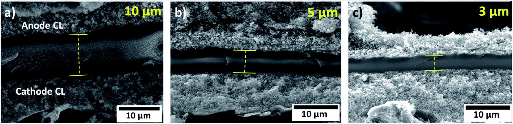 | ||
| Fig. 1 Scanning electron microscope images of MEA cross sections with directly deposited membranes with different thicknesses. (a) 10 μm membrane, (b) 5 μm membrane, (c) 3 μm membrane. | ||
As noted earlier, the DMD process requires a flat and smooth MPL surface to enable a crack-free, directly deposited MEA. Fig. 2a and b show SEM images of the anodic catalyst layer deposited onto a H23C6 GDL with different magnifications. As can be seen, a homogeneous morphology is achieved by the spray-coating process. Fig. 2c shows a SEM image of the directly deposited membrane on the anodic catalyst layer. The membrane exhibits a smooth and crack-free surface, which is prerequisite for low gas crossover and prevention of electrical shorts.
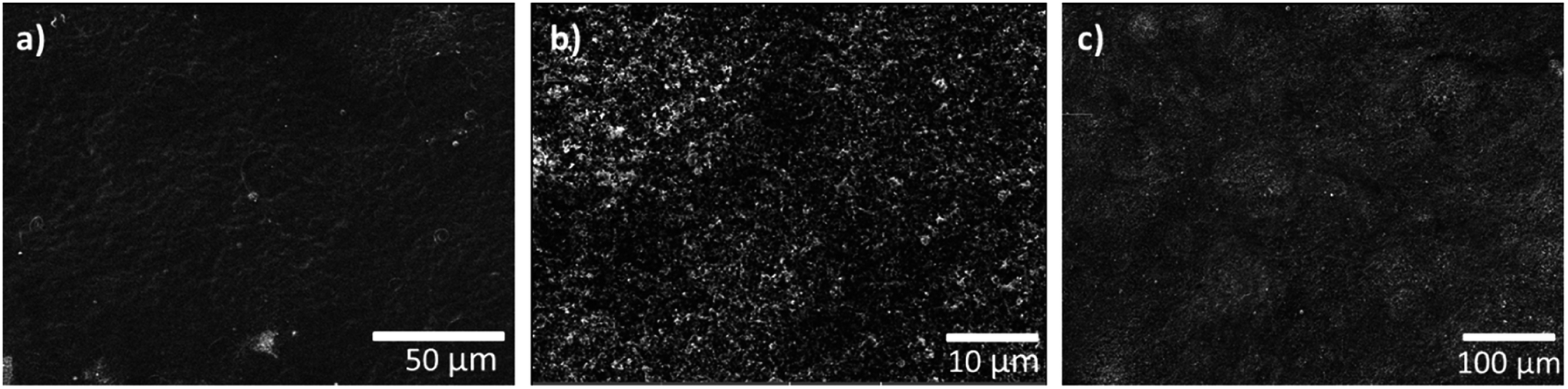 | ||
| Fig. 2 (a and b) Top view SEM images of anodic GDE in different magnifications. (c) Top view SEM image of anodic GDE with directly deposited membrane. | ||
Electrochemical properties
DMD cells with three different membrane thicknesses as well as the freestanding membrane/GDE cell were tested with H2/O2 gas feeds.It can clearly be seen in Fig. 3, that the freestanding membrane/GDE approach delivers by far the lowest performance of only 456 mW cm−2. Most likely, as typically reported for proton exchange membrane fuel cells, the poor ionic contact between gas diffusion electrode and membrane causes high losses.21 This effect is potentially exacerbated as after soaking, rinsing and drying, the membrane of only 10 μm thickness shows a very wrinkled surface. The delicate water balance in AEMFCs could be disturbed by this non-optimized interface between electrodes and membrane. Nonetheless, the highest AEMFC performances reported to date are based on this fabrication method.3,22
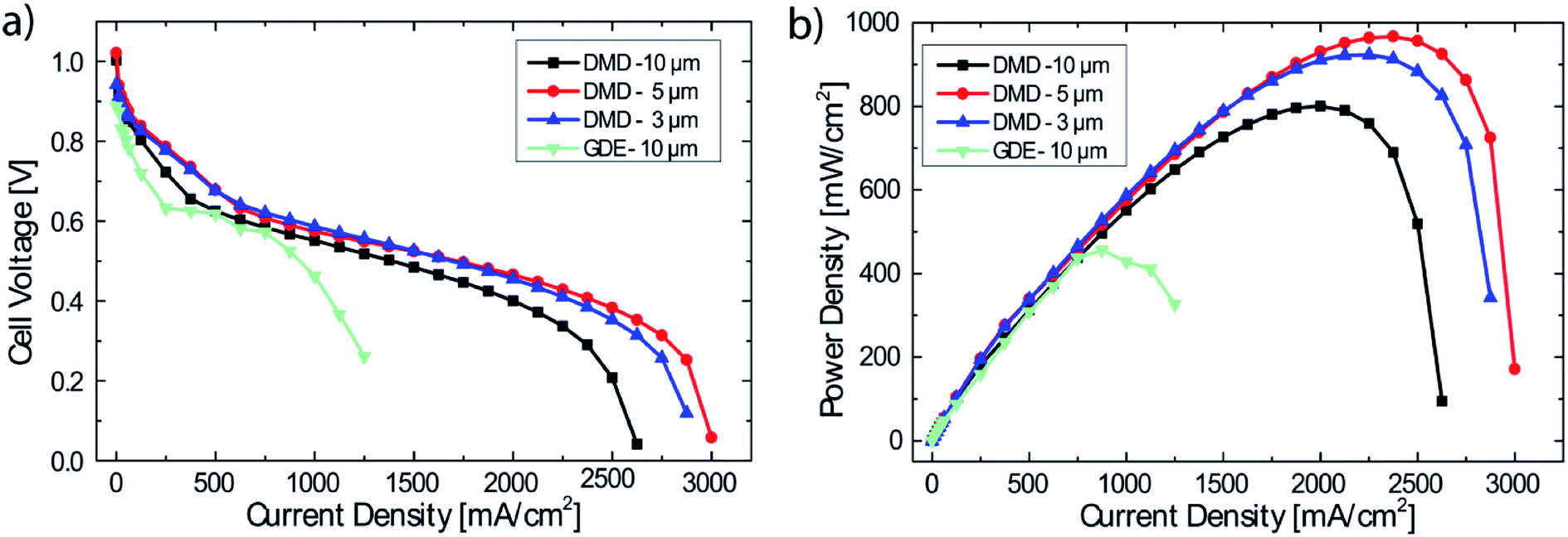 | ||
| Fig. 3 Performance data of DMD cells with different membrane thicknesses (3, 5, 10 μm) and GDEs with a 10 μm freestanding membrane. Operating conditions: anode/cell/cathode 69/70/70 °C, 0.5 slpm H2/O2, no back pressure (a) polarization data, (b) power density data. (For <62.5 mA cm−2 each measurement point held for 60 s, for ≥62.5 mA cm−2 each measurement point held for 90 s). | ||
DMD-10 shows a maximum power density of 800 mW cm−2 (compared to DMD-5 and DMD-3), which is likely a result of the thicker membrane, leading to increased ionic resistance (42 mOhm cm2 @ 2000 mA cm−2) and an earlier onset of mass transport losses. The increased mass transport losses can most probably be ascribed to the reduced water back diffusion from the anode to the cathode side caused by the thicker membrane,12,23 since all other fabrication and operation parameters were kept the same.
The DMD-5 shows slightly higher power densities (967 mW cm−2) than the DMD-3 (923 mW cm−2), which is most likely explainable by the very thin membrane: the cell with the 3 μm thick membrane shows a significantly lower OCV value of 0.94 V compared to 1.03 V for the DMD-5 which is a typical indicator for internal, electrical shorting and/or hydrogen gas crossover through the membrane.24 Apparently, the 3 μm membrane coating is not sufficient, to cover even minor imperfections on the surface of the GDE. This might lead to minor defects in the AEM, causing electrical shorts and local gas crossover through the membrane, resulting in the overall reduced fuel cell performance.17,24
Therefore, 5 μm membrane MEAs were chosen for further investigations. To test the MEA fabrication for reproducibility, 3 individual MEAs from different production batches, but identical catalyst loadings, membrane thickness and pre-treatment were tested. The mean of the polarization data, including error bars, is shown in Fig. 4. As can be seen, maximum deviations of ±60 mW cm−2 are observed for the medium current density region (1000 mA cm−2). The maximum power density at higher current densities is met in a very reproducible manner of only ±23 mW cm−2. This reliable batch-to-batch consistency enables a systematic study of the impact of relative humidity on the cell performance while excluding variations in fabrication.
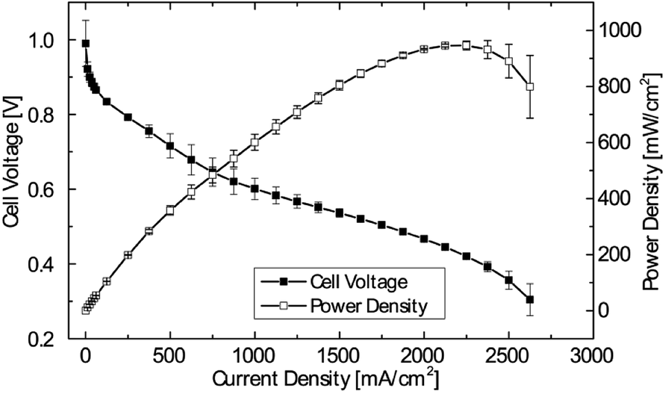 | ||
| Fig. 4 Mean with error bars of polarization curves and power density curves of 3 DMD cells with 5 μm membranes. Operating conditions: anode/cell/cathode 69/70/70 °C, 0.5 slpm H2/O2, no back pressure. (For <62.5 mA cm−2 each measurement point held for 60 s, for ≥62.5 mA cm−2 each measurement point held for 90 s). | ||
A systematic variation of the relative humidity is shown in Fig. 5. As can be seen in the power density data, in spite of significant changes in relative humidity between fully humidified conditions anode/cathode 98/100% (69/70 °C) and 80/87% (65/67 °C), a variation of less than 80 mW cm−2 (8%) in the maximum power density is measured. This is significantly more robust compared to recent results from literature, where a smaller window for stable operation was reported for AEMFCs, albeit with a different class of AEM.8 In that work, a change of only the anode gas feed dew point from 60 °C (100%) to 58 °C (91%) led to a change in the maximum power density of about 600 mW cm−2 (57%).8 The robustness to changes in relative humidity of the fuel cells described in this work is likely attributable to the very thin membranes, enabled by direct deposition: as motivated earlier, the use of very thin membranes is considered as key to access high performance, low power degradation as well as robust water balance between anode and cathode.22,25
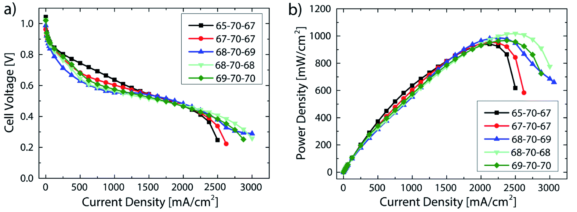 | ||
| Fig. 5 Performance data of DMD cells with 5 μm membranes at varying relative humidity. The numbers given in the legend refer to the gas feed and cell temperatures: i.e. 65-70-67 refers to 65 °C anodic gas feed, 70 °C cell temperature, 67 °C cathodic gas feed. Operating conditions: 0.5 slpm H2/O2, no back pressure (a) polarization data, (b) power density data. (For <62.5 mA cm−2 each measurement point held for 60 s, for ≥62.5 mA cm−2 each measurement point held for 90 s). | ||
The best fuel cell performance was achieved at a relative humidity of 91/91% (68/68 °C) with 1018 mW cm−2. As shown in Fig. 4, the highest performance reproducibility was achieved in the range of 2 A cm−2. Therefore, to better examine the effect of the relative humidity on the cell performance while excluding the variations in reproducibility, the ionic resistance at a current density of 2 A cm−2 are compared at different RH levels (Fig. 6).
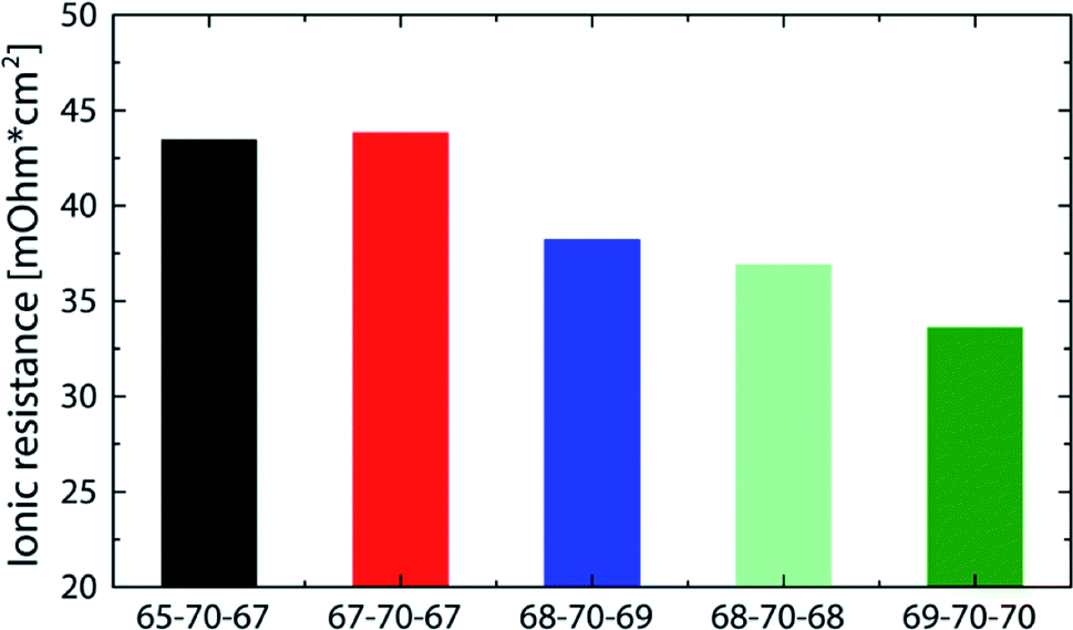 | ||
| Fig. 6 Comparison of the ionic resistance (measured at 2 A cm−2) for DMD cells with 5 μm membranes at different gas feed dew points (corresponding performance data in Fig. 5). The numbers given in the legend refer to the gas feed and cell temperatures. i.e. 65-70-67 refers to 65 °C anodic gas feed, 70 °C cell temperature, 67 °C cathodic gas feed. | ||
All bars in Fig. 6 feature an ionic resistance between 33 and 44 mOhm cm2 which again shows the minor sensitivity to varying gas feed dew points. Excluding the 65-70-67, bar all of them follow a general trend of a reduced resistance with increasing relative humidity. Although the 69-70-70 bar shows the lowest ionic resistance at 2 A cm−2 (33 mOhm cm2), it does not lead to the highest power density, which is most likely due to an earlier flooding of the anode caused by the high relative humidity. These results are in good agreement with former publications reporting anode flooding at high relative humidity leading to an earlier onset of mass transport limitations.11,23
Stability under operation
To investigate the performance stability of the AEMFCs, tests were conducted over 20 hours at fixed current densities of 600 mA cm−2. This current density was chosen as it was recently published by the DOE for long-term tests of AEMFCs in 2019.26 The main reason for the rapid degradation in AEMFCs is chemical degradation which is mainly caused by the instability of the cationic functional groups to hydroxide attack, but can also be a result of the degradation of the polymer backbone or the polymer-cationic group linkages.2 These degradations result in lower AEM conductivity and can eventually end in a complete device failure.4 The main degradation pathway for imidazoliums is the attack of an hydroxide ion at the C2 position which leads to a ring-opening reaction.2Before the test runs, the previously described break-in procedure and a polarization curve to <0.2 V was conducted. Only for the DMD-5 H2/O2 polarization to >0.6 V the break-in was adapted to a voltage hold of 2 minutes at 0.7 V and 5 minutes at 0.6 V and the I/V curve measurement was stopped at a cell potential of >0.6 V. Each measurement point during the polarization curve measurement was hold for 60 s at current densities <62.5 mA cm−2 and for 90 s for ≥62.5 mA cm−2. The only difference between the two DMD-5 cells was the break-in procedure and the polarization to different potentials before the long-term test.
All curves depicted in Fig. 7 show a strong cell voltage reduction in the first hour before reaching a quasi-linear region of degradation over the following 19 hours. The 5 μm cell which was polarized to <0.2 V shows an average voltage degradation rate of about 7.4 mV h−1. The 5 μm sample which was only polarized to >0.6 V shows a reduced voltage degradation in the first hour and has an average voltage reduction of 4.6 mV h−1 (2.9 mV h−1 if excluding the first hour of rapid degradation). This reduction of the degradation rate by more than 40% (fully polarized vs. partially polarized) might be explainable by the observations made by Dekel et al.: local dry-out of the cathode, which is promoted at higher current densities/lower cell potentials results in low lambda values (average hydration number of hydroxides) and thus in an accelerated degradation in the catalyst layer and of the membrane on the cathode side. This is due to the higher nucleophilicity of hydroxide ions which are solvated with few or even no water molecules.13,14 Therefore, the small change in the cell break-in procedure (avoiding high current densities/low cell potentials) enabled the significant reduction of voltage degradation.
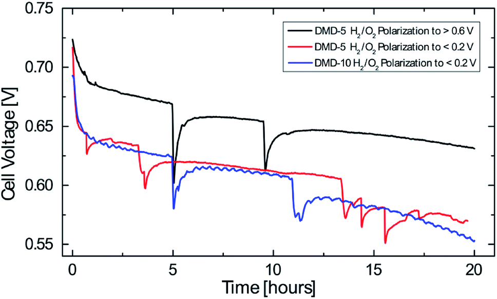 | ||
| Fig. 7 Cell voltage degradation over time at a constant current density of 600 mA cm−2 (plotted between 0.55 V and 0.75 V), operating conditions: anode/cell/cathode 68/70/68 °C, 0.5 slpm H2, 0.5 slpm O2, 1 slpm air, no back pressure. | ||
The 10 μm cell which was polarized to <0.2 V shows an average degradation rate of 7.4 mV h−1. After 20 hours, this cell shows a slightly lower cell voltage than the 5 μm cell which was polarized to <0.2 V. This might be due to the thicker membrane and the resulting reduced water back diffusion from anode to cathode side, which aggravates the water gradient inside the fuel cell. These results give an indication for the effect of water management on the AEMFC stability and the benefits of very thin membranes not only on cell performance but also on their stability. Nevertheless, the decay rates reported here, are still higher compared to the latest long-term tests for AEMFCs reporting average voltage decays of 0.068–0.4 mV h−1 and require further investigation.4,22
Conclusion
In this work, for the first time, anion exchange membrane fuel cells with solid polymer electrolyte thicknesses below 10 μm were investigated. Direct membrane deposition onto gas diffusion electrodes makes the application of solid polymer electrolytes in thicknesses between 3–10 μm possible. It was shown that a 5 μm solid polymer electrolyte layer enabled the best compromise between high power density and open circuit voltage. Additionally, a high reproducibility between three different MEA batches of only ±23 mW cm−2 (±2%) maximum power density variation is reported. This batch-to-batch reproducibility enabled a systematic study of the impact of relative humidity onto the cell performance: a variation of the relative humidity between 80 and 100% caused only minor variations in maximum power density of about 8%, with a peak performance of 1018 mW cm−2 at 91% RH on anode and cathode. This excellent robustness was attributed to the improved water management due to the ultra-thin membranes.Although the use of MPLs in AEMFCs was shown to result in lower performances,8 it is required for AEMFCs fabricated via the direct membrane deposition method.18 Therefore, future work will include the development of novel MPL structures with high gas diffusivity and hydrophilicity (cathode side) on the one hand and smooth and flat surface for subsequent MEA coating on the other hand.
Voltage degradation is still an open issue in the reported cells. The voltage decay in this work was already reduced by about 40% to an average voltage decay of 4.6 mV h−1 by avoiding excursions to higher current densities than 600 mA cm−2 in the break-in procedure, likely reducing deteriorating cathode dry-out. However, even this reduced voltage decay rate is still higher than the best current state of the art for AEMFCs. As was explained previously, there are different degradation processes taking place in an AEMFC and more research and optimization will be necessary to completely understand and circumvent them.
Conflicts of interest
Polybenzimidazolium AEM technology is licensed by Simon Fraser University to Ionomr Innovations Inc. Steven Holdcroft and Benjamin Britton are co-founders and minor shareholders of Ionomr Innovations Inc.Acknowledgements
This work was funded by the Vector Stiftung within the project “AlkaCell” and by the German Federal Ministry of Education BMBF within the German-Canadian research project “FlexCoat” (grant number 01DM19008A). Steven Holdcroft and Benjamin Britton acknowledge the Natural Sciences and Engineering Research Council of Canada for funding. The authors would like to acknowledge Peter Holzapfel for his contribution in the optimization of the spray-coating process and Claudia Schwarz for her support in electrode fabrication.References
- R. O'hayre, S.-W. Cha, F. B. Prinz and W. Colella, Fuel cell fundamentals, John Wiley & Sons, 2016 Search PubMed.
- S. Gottesfeld, D. R. Dekel, M. Page, C. Bae, Y. Yan, P. Zelenay and Y. S. Kim, Anion exchange membrane fuel cells, J. Power Sources, 2018, 375, 170–184 CrossRef CAS.
- G. Huang, M. Mandal, X. Peng, A. C. Yang-Neyerlin, B. S. Pivovar, W. E. Mustain and P. A. Kohl, Composite Poly(norbornene) Anion Conducting Membranes for Achieving Durability, Water Management and High Power (3.4 W/cm2) in Hydrogen/Oxygen Alkaline Fuel Cells, J. Electrochem. Soc., 2019, 637–644 CrossRef.
- D. R. Dekel, Review of cell performance in anion exchange membrane fuel cells, J. Power Sources, 2018, 375, 158–169, DOI:10.1016/j.jpowsour.2017.07.117.
- A. Liang and T. S. Zhao, Anion Exchange Membrane Fuel Cells. Principles, Materials and Systems, Springer, 2018 Search PubMed.
- N. Ziv, W. E. Mustain and D. R. Dekel, The Effect of Ambient Carbon Dioxide on Anion-Exchange Membrane Fuel Cells, ChemSusChem, 2018, 11, 1136–1150, DOI:10.1002/cssc.201702330.
- U. Krewer, C. Weinzierl, N. Ziv and D. R. Dekel, Impact of carbonation processes in anion exchange membrane fuel cells, Electrochim. Acta, 2018, 263, 433–446, DOI:10.1016/j.electacta.2017.12.093.
- T. J. Omasta, L. Wang, X. Peng, C. A. Lewis, J. R. Varcoe and W. E. Mustain, Importance of balancing membrane and electrode water in anion exchange membrane fuel cells, J. Power Sources, 2018, 375, 205–213, DOI:10.1016/j.jpowsour.2017.05.006.
- H.-S. Shiau, I. V. Zenyuk and A. Z. Weber, Water Management in an Alkaline-Exchange-Membrane Fuel Cell, ECS Trans., 2015, 69, 985–994, DOI:10.1149/06917.0985ecst.
- T. J. Omasta, A. M. Park, J. M. LaManna, Y. Zhang, X. Peng, L. Wang, D. L. Jacobson, J. R. Varcoe, D. S. Hussey, B. S. Pivovar and W. E. Mustain, Beyond catalysis and membranes, Energy Environ. Sci., 2018, 11, 551–558, 10.1039/C8EE00122G.
- T. J. Omasta, X. Peng, C. A. Lewis, J. Varcoe and W. E. Mustain, Improving Performance in Alkaline Membrane Fuel Cells through Enhanced Water Management, ECS Trans., 2016, 75, 949–954, DOI:10.1149/07514.0949ecst.
- L. Wang, M. Bellini, H. A. Miller and J. R. Varcoe, A high conductivity ultrathin anion-exchange membrane with 500+ h alkali stability for use in alkaline membrane fuel cells that can achieve 2 W cm −2 at 80 °C, J. Mater. Chem. A, 2018, 6, 15404–15412, 10.1039/C8TA04783A.
- D. R. Dekel, M. Amar, S. Willdorf, M. Kosa, S. Dhara and C. E. Diesendruck, Effect of Water on the Stability of Quaternary Ammonium Groups for Anion Exchange Membrane Fuel Cell Applications, Chem. Mater., 2017, 29, 4425–4431, DOI:10.1021/acs.chemmater.7b00958.
- C. E. Diesendruck and D. R. Dekel, Water – A key parameter in the stability of anion exchange membrane fuel cells, Curr. Opin. Electrochem., 2018, 9, 173–178, DOI:10.1016/j.coelec.2018.03.019.
- M. Adachi, T. Navessin, Z. Xie, F. H. Li, S. Tanaka and S. Holdcroft, Thickness dependence of water permeation through proton exchange membranes, J. Membr. Sci., 2010, 364, 183–193, DOI:10.1016/j.memsci.2010.08.011.
- M. Klingele, M. Breitwieser, R. Zengerle and S. Thiele, Direct deposition of proton exchange membranes enabling high performance hydrogen fuel cells, J. Mater. Chem. A, 2015, 3, 11239–11245, 10.1039/C5TA01341K.
- J. Will, A. Mitterdorfer, C. Kleinlogel, D. Perednis and L. J. Gauckler, Fabrication of thin electrolytes for second-generation solid oxide fuel cells, Solid State Ionics, 2000, 131(1–2), 79–96 CrossRef CAS.
- M. Breitwieser, T. Bayer, A. Büchler, R. Zengerle, S. M. Lyth and S. Thiele, A fully spray-coated fuel cell membrane electrode assembly using Aquivion ionomer with a graphene oxide/cerium oxide interlayer, J. Power Sources, 2017, 351, 145–150, DOI:10.1016/j.jpowsour.2017.03.085.
- P. Holzapfel, M. Bühler, C. Pham, F. Hegge, T. Böhm, D. McLauglin, M. Breitwieser and S. Thiele, Directly coated membrane electrode assemblies for proton exchange membrane water electrolysis, Electrochem. Commun., 2020, 110, DOI:10.1016/j.elecom.2019.106640.
- M. Breitwieser, C. Klose, A. Hartmann, A. Büchler, M. Klingele, S. Vierrath, R. Zengerle and S. Thiele, Cerium Oxide Decorated Polymer Nanofibers as Effective Membrane Reinforcement for Durable, High-Performance Fuel Cells, Adv. Energy Mater., 2017, 7, 1602100, DOI:10.1002/aenm.201602100.
- M. Breitwieser, M. Klingele, S. Vierrath, R. Zengerle and S. Thiele, Tailoring the Membrane-Electrode Interface in PEM Fuel Cells: A Review and Perspective on Novel Engineering Approaches, Adv. Energy Mater., 2018, 8, 1701257 CrossRef.
- L. Wang, X. Peng, W. E. Mustain and J. R. Varcoe, Radiation-grafted anion-exchange membranes, Energy Environ. Sci., 2019, 9, 2130, 10.1039/C9EE00331B.
- W. E. Mustain, Understanding how high-performance anion exchange membrane fuel cells were achieved, Curr. Opin. Electrochem., 2018, 12, 233–239, DOI:10.1016/j.coelec.2018.11.010.
- F. Barbir, PEM fuel cells: theory and practice, Academic press, ( 2013) Search PubMed.
- D. R. Dekel, I. G. Rasin and S. Brandon, Predicting performance stability of anion exchange membrane fuel cells, J. Power Sources, 2019, 420, 118–123, DOI:10.1016/j.jpowsour.2019.02.069.
- B. Pivovar, Advanced Ionomers & MEAs for Alkaline Membrane Fuel Cells, available at https://www.hydrogen.energy.gov/pdfs/review18/fc147_pivovar_2018_o.pdf, accessed 25 June 2019 Search PubMed.
| This journal is © The Royal Society of Chemistry 2020 |