
 Open Access Article
 This Open Access Article is licensed under a Creative Commons Attribution-Non Commercial 3.0 Unported Licence
Purification of metallurgical-grade silicon combining Sn–Si solvent refining with gas pressure filtration
Tianyang Li ,
Lei Guo,
Zhe Wang and
Zhancheng Guo*
,
Lei Guo,
Zhe Wang and
Zhancheng Guo*
State Key Laboratory of Advanced Metallurgy, University of Science and Technology Beijing, Beijing 100083, China. E-mail: zcguo@ustb.edu.cn
First published on 20th March 2020
Abstract
In this study, the purification of metallurgical-grade silicon using a combination of solvent refining and gas pressure filtration was investigated in the Sn–Si alloy. After the solvent refining process, the silicon was separated from the solvent by gas pressure filtration. The effects of pressure differentials (p), separation temperatures (T), and silicon contents in the alloy (ω(a)) on the separation efficiency were evaluated. The filtration result was improved with a higher pressure differential. The separation temperature had little effect on the separation efficiency, whereas a higher silicon content in the alloy led to a decrease of the separation efficiency. The final purification result after separation was examined, and a better separation contributed to the removal of impurity. The optimal result for separation was obtained at p = 0.30 MPa, T = 250 °C, and ω(a) = 20 wt%, and 93.6% of tin was separated into the filtrate, while almost all the silicon was recovered and formed the separated silicon with a silicon content of 80.0 wt%. At the same time, most impurities were eliminated and 94.9% of B was removed after refining the sample twice.
1. Introduction
The abundant and low-cost solar-grade silicon (SoG-Si) feedstock is essential for the widespread use of solar cells. The traditional method for SoG-Si production (the Siemens process) has less potential in reducing the cost. The high consumption of chemical energy is inevitable in the Siemens process, because the conversion of metallurgical-grade silicon (MG-Si) to gaseous compounds is followed by distillation, reduction, and deposition into high-purity silicon.1 Therefore, metallurgical refining, a promising process for producing SoG-Si, has gradually become a topic of interest. It is based on a low-cost metallurgical purification technique, using MG-Si as the starting material and preventing silicon from becoming involved in a chemical reaction. The purification of MG-Si by metallurgical methods, such as solvent refining,2,3 slag refining,4 directional solidification,5 and so on,6,7 has been investigated.MG-Si (purity, 90%∼99.9%) contains more impurities than SoG-Si (purity, 99.999%∼99.9999%), which are mainly metallic impurities, boron, and phosphorus. The removal of boron and phosphorus from MG-Si by metallurgical methods is relatively difficult compared with that of metallic impurities.2,5 Solvent refining is efficient for the removal of impurities from MG-Si, including boron and phosphorus. It relies on the impurities preferentially segregating into the liquid phase during the solidification process. Many metals, such as tin,8,9 aluminum,10 copper,11 and iron,12 have been proved to be suitable solvents that could decrease the segregation coefficient of impurity contributing to its removal from the silicon. Among them, the Sn–Si system is highly efficient for the removal of boron. The segregation coefficient of boron in the Sn–Si melt can decrease to 0.038, far less than 0.8, which is the coefficient of boron in pure silicon.9 In addition, neither eutectic phase nor intermetallic compound is generated in the Sn–Si alloy, which means no loss of silicon during the refining process. Therefore, solvent refining in the Sn–Si system is promising for the purification of MG-Si.
Solvent refining has been proved as a potential method,9,13 but the separation of refined silicon from the solvent needs to be improved. Direct acid leaching is clearly undesirable due to the massive loss of tin and generation of waste acid.14 The electromagnetic force can agglomerate the silicon under an alternating magnetic field during the solidification process,15,16 but much tin still remains in the enriched silicon. Separation under centrifugal force is effective, but difficult to widely apply.17 A novel method of gas pressure filtration was investigated for the separation of silicon in the Al–Si solvent refining process,18 and was demonstrated to be a promising method with a high efficiency.
In this work, a method combining gas pressure filtration and Sn–Si solvent refining was studied for the purification of MG-Si and the separation of purified silicon from solvent. The influences of pressure differentials (p), separation temperatures (T), and silicon contents in the alloy (ω(a)) on the separation efficiency were investigated, and final purification results after separation process were examined.
2. Experimental
2.1 Apparatus
Gas pressure filtration, a method of strengthening mass transfer under the driving force of a pressure differential, can separate a liquid phase from solid particles. During the filtration process, the liquid melt is forced through the filtration media by the applied pressure while the solid particles are intercepted. The filtration apparatus is shown in Fig. 1, and it was produced by Hefei Kejing Material Technology Co., Ltd in China. It mainly consisted of an induction heating furnace and a pressurization system. The temperature was controlled by a program controller with a type B thermocouple. A graphite crucible was used for placing the sample and enclosing spaces. A carbon fiber felt (CFF) with a thickness of 3 mm was supplied by Jing Long Te Tan Ltd in China and was used as the filtration media in this work. It has a real density of 1.82 g cm−3, bulk density of 0.171 g cm−3, and average fiber diameter of 17 μm. The graphite flake had 20 uniformly distributed holes (2 mm in diameter), which were used to support the CFF and had little effect on the filtration process. The chamber in the apparatus was divided into two parts when the sample melted, and the upper part could be pressurized with a gasholder. The molten tin passed through the CFF by applying the pressure differential until the two parts of the chamber were connected.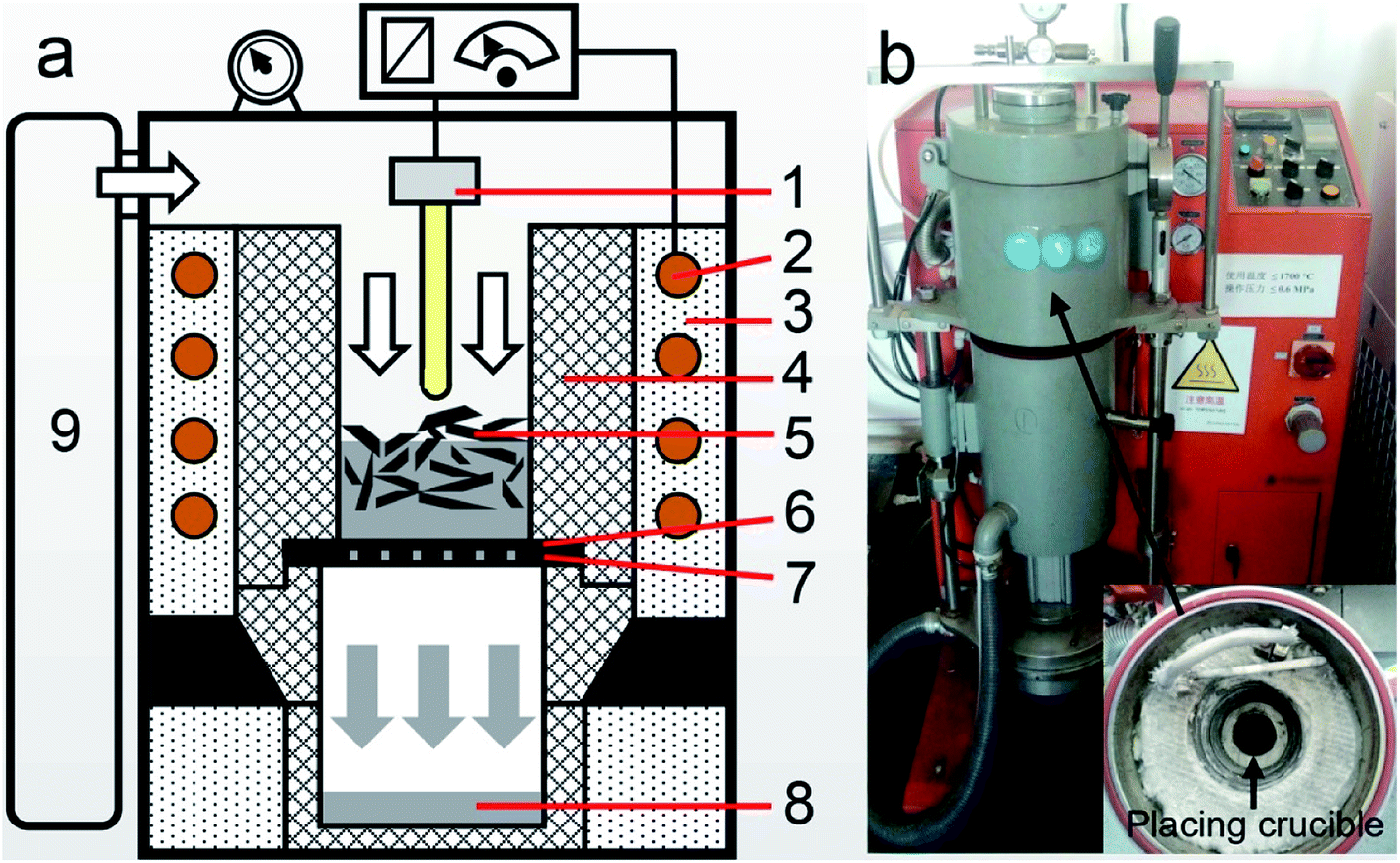 | ||
| Fig. 1 (a) Schematic and (b) photograph of the pressurized filtering apparatus. ((1) Thermocouple, (2) induction coil, (3) thermal insulation materials, (4) graphite crucible, (5) separated silicon, (6) carbon fiber felt, (7) graphite flake, (8) filtrate, (9) gasholder). | ||
2.2 Methods
The materials used in this work were MG-Si (99.6 wt% purity) and tin (99.99 wt% purity), and the impurity content in the raw materials was presented in a later section (Table 1). First, MG-Si was blended with the tin to form a mixture with varying weight percentages of silicon. Approximately 60 g of this mixture was placed in the graphite crucible of the apparatus. Then, the temperature of the apparatus was raised to 1500 °C and held for 1 h under argon atmosphere to melt the mixture. Third, the temperature was cooled to the separation temperature (250–850 °C) at 3 °C min−1 and held for 30 min contributing to the crystallization of silicon and segregation of impurity.9,10 Above mentioned was the solvent refining process. Next the separation process following, by applying a certain pressure of argon gas (0.05–0.3 MPa), the liquid tin was forced to flow through CFF and formed the filtrate, while the unfiltered part was intercepted by CFF and thought of as the separated silicon. Finally, the separated silicon was cleaned with hydrochloric acid (70 °C for 2 h) after crushing (100 μm) for the removal of residual solvent, which obtained the refined silicon. The refined silicon was the product of this combined method for the MG-Si purification.| Element (i) | B | P | Al | Fe | Ti | V |
|---|---|---|---|---|---|---|
| MG-Si (Ci_0) | 31.5 | 54.3 | 521.4 | 2388.4 | 303.2 | 373.6 |
| Sn | 4.3 | 1.4 | 3.2 | 9.8 | 5.8 | 4.7 |
| Refined silicon (Ci_r) | 6.2 | 17.8 | 76.2 | 1048.5 | 81.5 | 87.4 |
| Removal fraction in the first refining (Ri) | 80.3% | 67.1% | 85.4% | 56.1% | 73.1% | 76.6% |
| Secondary refined silicon | 1.6 | 12.9 | 18.3 | 198.2 | 9.8 | 9.1 |
| Removal fraction in the second refining | 94.9% | 76.3% | 96.5% | 91.7% | 96.8% | 97.6% |
To evaluate the separation efficiency, two parameters were investigated, including the silicon content in the separated silicon (ω(s)) and the residual ratio of tin (η). The silicon content in the separated silicon (ω(s)) was measured, which obtained the weight of silicon in the tested specimen by dissolving tin with hydrochloric acid. The residual ratio of tin (η) was defined using eqn (1):
 | (1) |
As the assessment of impurity removal from silicon, the removal fraction of impurity element (Ri) was calculated by eqn (2):
 | (2) |
2.3 Characterization
The separated silicon and filtrate were sectioned into two parts along the longitudinal center axes and then polished to a 1 μm finish for X-ray diffraction (XRD, SmartLab, Rigaku, Japan), optical microscopy (DM4M, Leica, Germany), scanning electron microscopy and energy dispersive X-ray spectroscopy (SEM-EDS, Phenom Prox, Phenom, Netherlands) analyses. The impurity content in the refined silicon was at a ppm level,10,17 while the silicon content in the filtrate was in the range of 0.05 wt% to 0.3 wt%. Therefore, the concentrations of impurity in refined silicon were analyzed by Inductively Coupled Plasma Mass Spectrometry (ICP-MS, ICP RQ, Thermo Fisher Scientific, USA), and the silicon content in the filtrate was analyzed by Inductively Coupled Plasma Optical Emission Spectrometry (ICP-OES, Optima 7000DV, PerkinElmer, USA). The two measurement methods were similar, except for the fact that different instruments were used. The sample was firstly dissolved into the solution by hydrofluoric acid and nitric acid, and the content of target element in the solution was then analyzed by ICP-MS/OES to obtain the impurity content in refined silicon or the silicon content in filtrate.3. Results and discussion
3.1 Solvent refining process
In this work, the solvent refining was first completed. In the cooling process after the melting of tin and silicon, the silicon was firstly crystallized, while the impurities was not precipitated with silicon and preferentially segregated into the solvent.2,8 Therefore, the high-purity silicon was obtained, and the impurities came into the molten tin. The impurities in MG-Si and Sn–Si alloy after refining process are present in Fig. 2.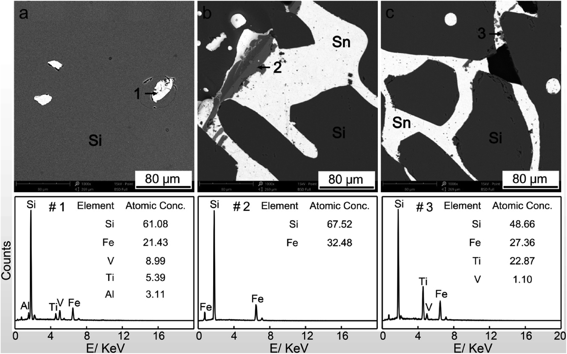 | ||
| Fig. 2 Morphologies of impurities in (a) MG-Si and (b and c) Sn–Si alloy after refining process. | ||
There were many impurities in the MG-Si, which were the bright white particles in Fig. 2a. They were mainly iron matrix impurities detected by energy-dispersive X-ray spectroscopy (EDS) point analysis (point#1 in Fig. 2a). According to the Sn–Si binary phase diagram,19 the vast majority of silicon precipitated into solid phase above 1200 °C, and the formed silicon grains exhibited a large size (black parts in Fig. 2b and c). These silicon grains contained almost no impurities, while the impurity elements segregated into the solvent, as shown in Fig. 2b and c. Most iron impurity existed in the binary silicide phase of FeSi2, detected by EDS point analysis (point#2 in Fig. 2b), and its particle size was obviously larger than that of other impurity. The Ti, V, and some Fe formed multicomponent phases (point#3 in Fig. 2c) and surrounded by the tin. The mentioned above are basically consistent with other works.9,17
The high-purity silicon grains were obtained after solvent refining, but they were still mixed with the solvent (tin). At the same time, the impurities distributed in the solvent also need to be removed. Since they are the main focus in this study, the separation of silicon from solvent by gas pressure filtration and final purification result in this combined method were investigated.
3.2 Separation efficiency of silicon by gas pressure filtration
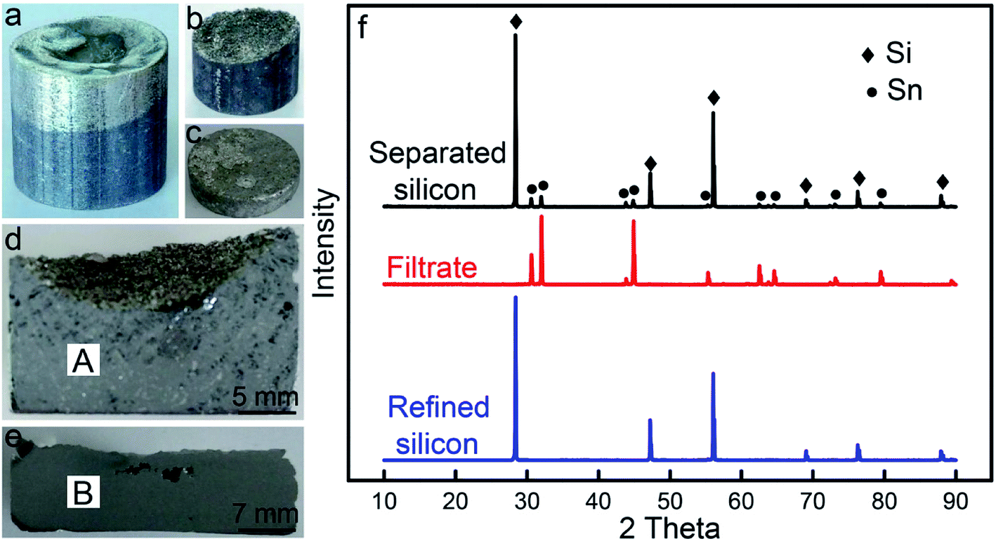 | ||
| Fig. 3 Results of filtering separation at p = 0.15 MPa, T = 250 °C, and ω(a) = 20 wt%. Pictures of (a) Sn–Si alloy before filtration; (b) separated silicon and (c) filtrate; sections of (d) separated silicon and (e) filtrate; and (f) X-ray diffraction (XRD) patterns of separated silicon, filtrate, and refined silicon. | ||
The micro-morphologies of the separated silicon and filtrate observed by optical microscopy are presented in Fig. 4, referred to as areas ‘A’ and ‘B’ in Fig. 3, respectively. In the separated silicon, the silicon grains exhibited a size of a millimeter magnitude and a few residual tin remained in the voids (Fig. 4a). There were no large sized grains in the filtrate, and the black particle with a tiny size in the filtrate was the silicon (Fig. 4b). The silicon content in the separated silicon (ω(s)) and the residual ratio of tin (η) were 74.2 wt% and 9.1%, respectively, while the silicon content in the filtrate was only 0.08 wt%. It means that almost all the silicon was recovered and over 90% tin was separated, consistent with Fig. 3f. So it could be concluded that the separation of silicon from the solvent was achieved by the gas pressure filtration.
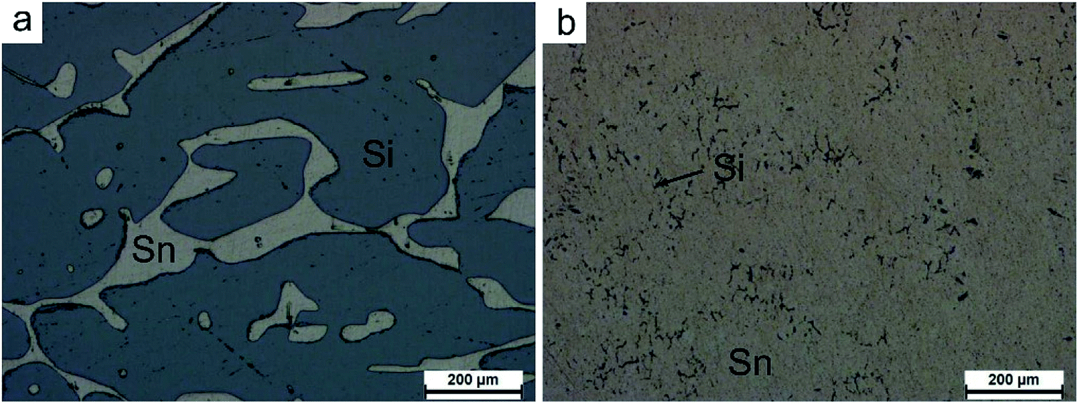 | ||
| Fig. 4 Optical images of (a) separated silicon and (b) filtrate (areas ‘A’ and ‘B’ in Fig. 3, respectively). | ||
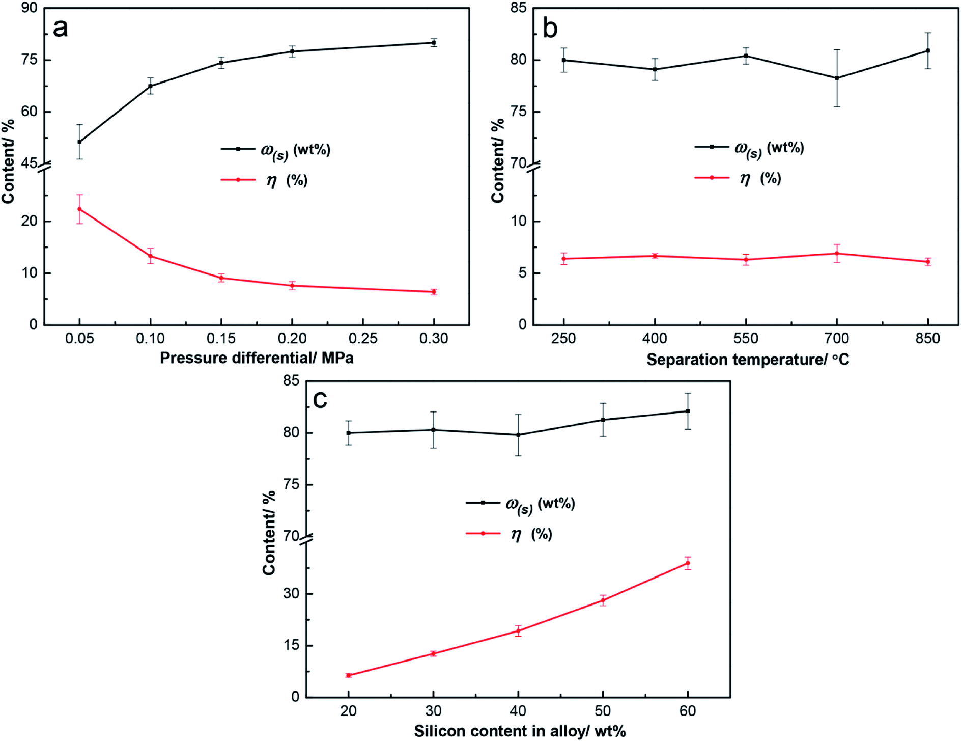 | ||
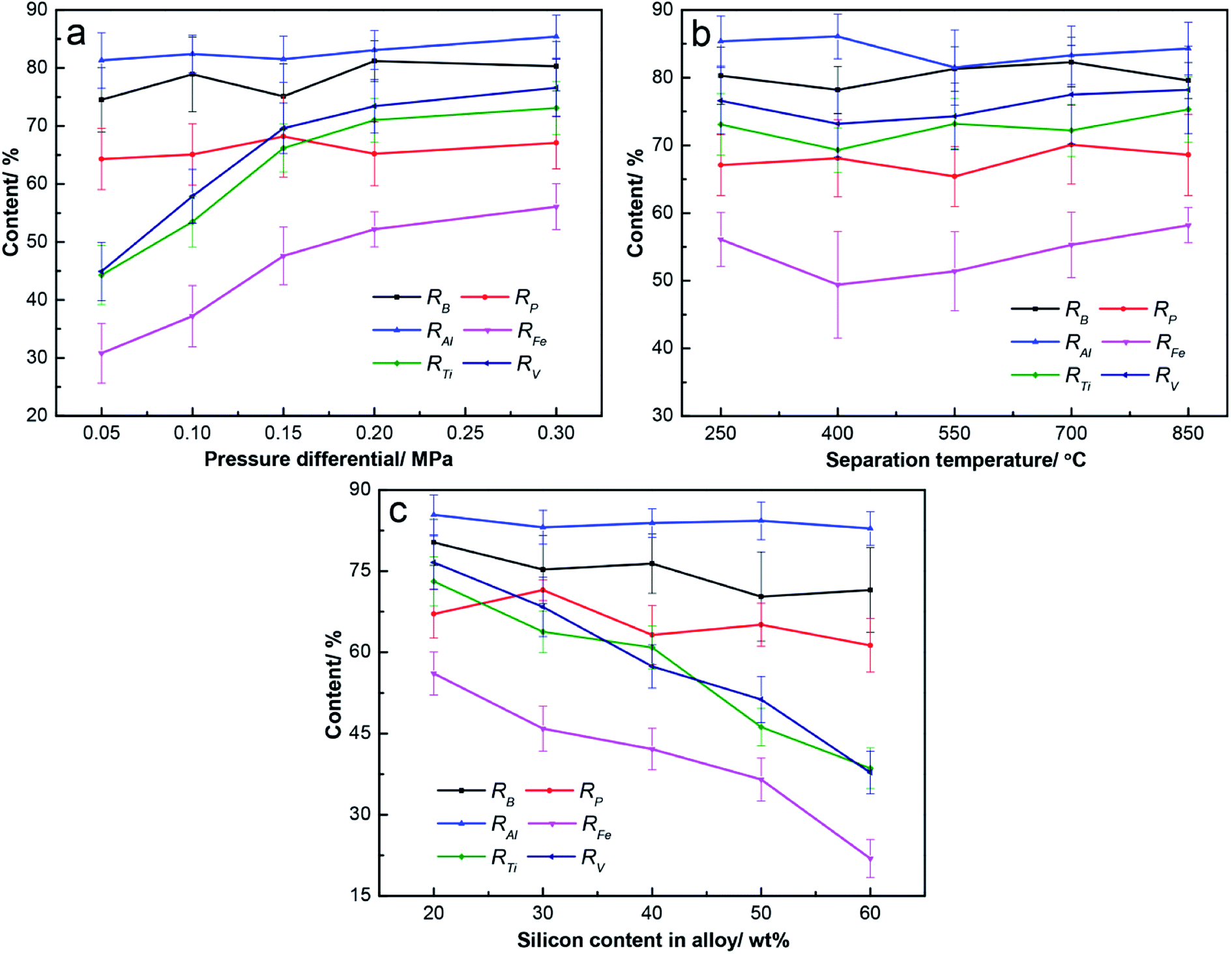
| Fig. 5 Separation efficiencies with (a) pressure differential at T = 250 °C and ω(a) = 20 wt%, (b) separation temperature at p = 0.30 MPa and ω(a) = 20 wt%, and (c) alloy composition at p = 0.30 MPa and T = 250 °C. | ||
The pressure differential is the key factor in this method, and it can make answers to the questions that whether efficient separation is achieved and how to meet its demand. The effect of pressure differentials on separation was evaluated at T = 250 °C and ω(a) = 20 wt%, as shown in Fig. 5a. The value of 250 °C was chosen as the separation temperature to ensure sufficient superheat, while the melting point of tin is 232 °C. The separation results were better with higher pressure differentials. At p = 0.05 MPa, the result was undesirable, with ω(s) of 51.4 wt% and η of 22.3%. Additionally, the results were efficient when p ≥ 0.15 MPa, with ω(s) over 74.2 wt% and η below 9.1%. At p = 0.30 MPa, the ω(s) was 80.0 wt% and η was 6.4%. The curve plateau of the separation results was reached at p = 0.20 MPa, and the improvement of separation efficiency was not obvious at p ≥ 0.20. The efficient filtration results could be obtained without a high pressure differential, which is the advantage of this combined method.
Since optimal separation was achieved at p = 0.30 MPa, the effect of the separation temperature on filtration was investigated at p = 0.30 MPa and ω(a) = 20 wt%, as shown in Fig. 5b. The ω(s) fluctuated in the range of 78.3 wt% to 80.9 wt% at T = 250–850 °C, and η was around 6.5%. Varied separation temperatures had little effect on the separation efficiency. According to the phase diagram of the Sn–Si alloy,19 Sn–Si alloy melts mainly consist of molten tins and silicon grains from 232 °C to 1200 °C, and their amounts varied less with the temperature. Therefore, similar results were obtained, and 250 °C is a better choice because of the low superheat.
Based on the above results, the effect of the alloy composition on separation was examined at p = 0.30 MPa and T = 250 °C, as shown in Fig. 5c. From ω(a) = 20 wt% to ω(a) = 60 wt%, the silicon content in separated silicon gradually increased from 80.0 wt% to 82.1 wt%, but η sharply increased from 6.4% to 38.9%. The separation efficiency obviously reduced with the higher silicon in the alloy, and the optimal result with ω(s) of 80.0 wt% and η of 6.4% was obtained at ω(a) = 20 wt%. A higher amount of silicon in the alloy means more solid phases during the filtration process, which contributed to the decrease of the separation efficiency.
Optimal separation was obtained at p = 0.30 MPa, T = 250 °C, and ω(a) = 20 wt%; 93.6% of tin was separated into the filtrate; and the separated silicon was obtained with a silicon content of 80.0 wt%. In all of the above experiments, the silicon content in the filtrate was less than 0.3 wt%, as shown by ICP-OES. This means that the filtrate was basically the tin and almost all the silicon in the Sn–Si alloy remained in the separated silicon. This method is proved to be efficient for the separation of silicon.
 | (3) |
3.3 Purification efficiency in the combined method
The purification efficiency was studied after the separation results had been investigated. The concentrations of impurity in the refined silicon were analyzed by ICP-MS, and the removal fraction of impurity element (Ri) was calculated via eqn (2). Impurity removals in the combined method are presented in Fig. 6, while the impurity contents in MG-Si and tin are shown in Table 1.
 | ||
| Fig. 6 Impurity removals with (a) pressure differential at T = 250 °C and ω(a) = 20 wt%, (b) separation temperature at p = 0.30 MPa and ω(a) = 20 wt%, and (c) alloy composition at p = 0.30 MPa and T = 250 °C. | ||
The removal of Fe, Ti, and V enhanced with the increasing pressure differential, while the removal of B, P, and Al exhibited little change, as shown in Fig. 6a. Upon increasing the pressure differential from 0.05 to 0.30 MPa, the removal fraction of B and P fluctuated in the range of 74.5% to 81.2% and 64.3% to 68.2%, respectively, and RAl fluctuated in the range of 81.3% to 85.4%. The removal of Fe, Ti, and V was inefficient at p = 0.05 MPa, and only 30.8% of Fe, 44.3% of Ti, and 44.9% of V were removed during the refining process. Furthermore, their removal was improved at p = 0.30 MPa, at which point 56.1% of Fe, 73.1% of Ti, and 76.6% of V were eliminated in the refined silicon. It can be found that the plateaus in the curves of RFe, RTi and RV were reached at 0.15 MPa or 0.2 MPa, and similar to that in the curve of separation result (Fig. 5a).
The purification efficiency with separation temperature fluctuated to a certain extent, as shown in Fig. 6b. The RB and RP fluctuated in the range of 78.2% to 82.3% and 65.4% to 70.1%, respectively, at T = 250–850 °C. The removal of metallic impurity was also not changed notably with the increase of temperature, including all of the Al, Fe, Ti, and V. The RAl and RFe fluctuated in the range of 81.5% to 86.5% and 49.4% to 58.2%, while RTi and RV fluctuated in the range of 69.3% to 75.3% and 73.2% to 78.2%, respectively.
The removal fraction of Fe, Ti, and V significantly reduced with a higher silicon content in the alloy, while the removal of B, P, and Al fluctuated to a certain extent, as shown in Fig. 6c. From ω(a) = 20 wt% to ω(a) = 60 wt%, the RB and RP fluctuated in the range of 70.3% to 80.3% and 61.3% to 71.5%, respectively, and RAl fluctuated in the range of 82.9% to 85.4%. More Fe, Ti, and V remained in the refined silicon when increasing the silicon content in the alloy: RFe reduced from 56.1% to 21.9%, while RTi and RV decreased from 73.1% to 38.6% and 76.6% to 37.8%, respectively.
Compared with Fig. 5, the removal of Fe, Ti, and V is consistent with the separation efficiency of silicon under different conditions, while the removal of B, P, and Al was almost unchanged. The purification result obtained after the optimal separation (at p = 0.30 MPa, T = 250 °C, and ω(a) = 20 wt%) was efficient, and the removal of B (80.3%) and P (67.1%) was comparable to the results presented in other literature, but the removal of metallic impurity (56.1% of Fe, 73.1% of Ti, and 76.6% of V) was less efficient, especially the iron removal.8,9,17
In the combined method of this study, most impurities were in the company of molten tin and passed into the filtrate due to their tiny particle size. The poor separation efficiency led to more residues of molten tin and impurities in the separated silicon. Most notably, the particle size of FeSi2 phase was obviously larger than that of other impurities (Fig. 2b), which made it difficult to separate and kept it in the separated silicon. All of the Ti, V, and FeSi2 were difficult to dissolve using hydrochloric acid, and they remained in the refined silicon. Therefore, a better separation contributed to impurity removal.
3.4 Comparison with other methods
As a physical method, the method combining solvent refining and gas pressure filtration is believed to be superior to traditional method (the Siemens process) because of the simple process and its low energy consumption.1 In the case of similar effect for the impurity removal in solvent refining process, the subsequent separation process may become another key to its application. Compared with the direct acid leaching after refining, there was over 90% reduction in the acid consumption using gas pressure filtration, and most solvent can be recycled. As for the method of electromagnetic enrichment, its separation efficiency was investigated in the Al–Si system,25 similar to the Sn–Si alloy. In the silicon enrichment part of Al–45% Si alloy, the silicon content was less than 70 wt%, measured by Yu.25 Considering that the density of tin (7.28 g cm−3) is clearly higher than that of aluminum (2.7 g cm−3), gas pressure filtration is more efficient in the separation, which means that less acid is consumed and more solvent is recycled. In the centrifugal separation, Li obtained the separated silicon from Al–45% Si alloy, while its silicon content was close to 90 wt% (91.4 vol%) and most of the available silicon was kept in it.10 In this study, the comparable results were achieved in Sn–Si alloy by gas pressure filtration (80.0 wt% converting to 92.6 vol%). Since this method can be more easily scaled up, the combination of solvent refining and gas pressure filtration can serve an important role in the MG-Si purification.4. Conclusions
In this study, the combination of solvent refining and gas pressure filtration was proved to be a promising method. After solvent refining process, efficient separation of silicon from solvent could be obtained at a low pressure differential. Optimal separation result was obtained at p = 0.30 MPa, T = 250 °C, and ω(a) = 20 wt%, and 93.6% of tin was separated into the filtrate, while almost all the silicon was recovered and formed the separated silicon with a silicon content of 80.0 wt%. A better separation contributed to the removal of impurity. After a twice-refining process, most impurities were eliminated and 94.9% of B was removed.Abbreviations
The following abbreviations are used in this manuscript:| SoG-Si | Solar-grade silicon |
| MG-Si | Metallurgical-grade silicon |
| CFF | Carbon fiber felt |
Conflicts of interest
There are no conflicts to declare.Acknowledgements
The authors acknowledge the financial supports from the National Natural Science Foundation of China (No. 51804030), the National Key Research and Development Program (2016YFB0601304), and the Fundamental Research Funds for the Central Universities (FRF-TP-19-010A2).References
- F. Chigondo, From metallurgical-grade to solar-grade silicon: an overview, Silicon, 2018, 10, 789–798 CrossRef CAS.
- J. W. Li, Z. C. Guo, H. Q. Tang, Z. Wang and S. T. Sun, Si purification by solidification of Al–Si melt with super gravity, Trans. Nonferrous Met. Soc. China, 2012, 22, 958–963 CrossRef CAS.
- T. Yoshikawa and K. Morita, Refining of silicon during its solidification from a Si–Al melt, J. Cryst. Growth, 2009, 311, 776–779 CrossRef CAS.
- J. Wu, Y. Li, K. Wei, Y. Bin and Y. Dai, Boron removal in purifying metallurgical grade silicon by CaO–SiO2 slag refining, Trans. Nonferrous Met. Soc. China, 2014, 24, 1231–1236 CrossRef CAS.
- Y. Tan, S. Ren, S. Shi, S. Wen, D. Jiang, W. Dong, M. Ji and S. Sun, Removal of aluminum and calcium in multicrystalline silicon by vacuum induction melting and directional solidification, Vacuum, 2014, 99, 272–276 CrossRef CAS.
- K. Liu, J. Wu, K. Wei, W. Ma, K. Xie, S. Li, B. Yang and Y. Dai, Application of molecular interaction volume model on removing impurity aluminum from metallurgical grade silicon by vacuum volatilization, Vacuum, 2015, 114, 6–12 CrossRef CAS.
- W. Lee, J. Kim, B. Jang, Y. Ahn, H. Lee and W. Yoon, Metal impurities behaviors of silicon in the fractional melting process, Sol. Energy Mater. Sol. Cells, 2011, 95, 59–62 CrossRef CAS.
- X. Ma, T. Yoshikawa and K. Morita, Purification of metallurgical grade Si combining Si–Sn solvent refining with slag treatment, Sep. Purif. Technol., 2014, 125, 264–268 CrossRef CAS.
- L. X. Zhao, Z. Wang and Z. C. Guo, Low-temperature purification process of metallurgical silicon, Trans. Nonferrous Met. Soc. China, 2011, 21, 1185–1192 CrossRef CAS.
- J. W. Li, Z. C. Guo, J. C. Li and L. Z. Yu, Super gravity separation of purified Si from solvent refining with the Al–Si alloy system for solar grade silicon, Silicon, 2015, 7, 239–246 CrossRef CAS.
- M. Li, T. Utigard and M. Barati, Removal of boron and phosphorus from silicon using CaO–SiO2–Na2O–Al2O3 flux, Metall. Mater. Trans. B, 2014, 45, 221–228 CrossRef CAS.
- S. Esfahani and M. Barati, Purification of metallurgical silicon using iron as impurity getter part II: extent of silicon purification, Met. Mater. Int., 2011, 17, 1009–1015 CrossRef CAS.
- L. Hu, Z. Wang, X. Gong, Z. Guo and H. Zhang, Purification of metallurgical-grade silicon by Sn–Si refining system with calcium addition, Sep. Purif. Technol., 2013, 118, 699–703 CrossRef CAS.
- J. L. Gumaste, B. C. Mohanty, R. K. Galgali, U. Syamaprasad, B. B. Nayak, S. K. Singh and P. K. Jena, Solvent refining of metallurgical grade silicon, Sol. Energy Mater., 1987, 16, 289–296 CrossRef CAS.
- J. Jie, Q. Zou, J. Sun, Y. Lu, T. Wang and T. Li, Separation mechanism of the primary Si phase from the hypereutectic Al–Si alloy using a rotating magnetic field during solidification, Acta Mater., 2014, 72, 57–66 CrossRef CAS.
- X. Ma, T. Yoshikawa and K. Morita, Si growth by directional solidification of Si–Sn alloys to produce solar–grade Si, J. Cryst. Growth, 2013, 377, 192–196 CrossRef CAS.
- L. Hu, Z. Wang, X. Gong, Z. Guo and H. Zhang, Impurities removal from metallurgical–grade silicon by combined Sn–Si and Al–Si refining processes, Metall. Mater. Trans. B, 2013, 44, 828–836 CrossRef CAS.
- T. Li, L. Guo, Z. Wang and Z. Guo, Separation of refined silicon from Al–Si alloys by air pressure filtration, Metall. Mater. Trans. B, 2019, 50, 1171–1179 CrossRef CAS.
- J. Li, Y. Liu, Y. Tan, Y. Li, L. Zhang, S. Wu and P. Jia, Effect of tin addition on primary silicon recovery in Si–Al melt during solidification refining of silicon, J. Cryst. Growth, 2013, 371, 1–6 CrossRef CAS.
- Q. C. Zou, J. C. Jie, J. L. Sun, T. M. Wang, Z. Q. Cao and T. J. Li, Effect of Si content on separation and purification of the primary Si phase from hypereutectic Al–Si alloy using rotating magnetic field, Sep. Purif. Technol., 2015, 142, 101–107 CrossRef CAS.
- Q. C. Zou, J. C. Jie, S. C. Liu, T. M. Wang, G. M. Yin and T. J. Li, Effect of traveling magnetic field on separation and purification of Si from Al–Si melt during solidification, J. Cryst. Growth, 2015, 429, 68–73 CrossRef CAS.
- Z. Wang, J. Gao, A. Shi, L. Meng and Z. Guo, Recovery of zinc from galvanizing dross by a method of super–gravity separation, J. Alloys Compd., 2018, 735, 1997–2006 CrossRef CAS.
- T. R. Hogness, The surface tensions and densities of liquid mercury, cadmium, zinc, lead, tin and bismuth, J. Am. Chem. Soc., 1921, 43, 1621–1628 CrossRef CAS.
- J. Murai, T. Marukawa, T. Mima, S. Arai, K. Sasaki and H. Saka, Size dependence of the contact angle of liquid clusters of Bi and Sn supported on SiO2, Al2O3, graphite, diamond and AlN, J. Mater. Sci., 2006, 41, 2723–2727 CrossRef CAS.
- W. Yu, W. Ma, G. Lü, Y. Ren, H. Xue and Y. Dai, Si purification by enrichment of primary Si in Al–Si melt, Trans. Nonferrous Met. Soc. China, 2013, 23, 3476–3481 CrossRef CAS.
| This journal is © The Royal Society of Chemistry 2020 |