 Open Access Article
Fe, N-doped carbon spheres prepared by electrospinning method as high efficiency oxygen reduction catalyst†
Hanzeng Zoua,
Supeng Pei *a,
Zongshang Zhoua,
Zhaoyan Chena,
Xia Xionga,
Yueyang Suna and
Yongming Zhangb
aSchool of Chemical and Environmental Engineering, Shanghai Institute of Technology, Shanghai 201418, China. E-mail: peisupeng@126.com
bShanghai Jiao Tong University, No. 800 Dongchuan Rd., Minhang District, Shanghai 200240, China
First published on 3rd January 2020
Abstract
Electrocatalysts for the oxygen reduction reaction (ORR) are crucial in metal–air batteries, fuel cells and other electrochemical devices. In this study, iron and nitrogen co-doped carbon sphere electrocatalysts were synthesized by electrospinning and thermal treatment. According to the results, the catalyst marked as Fe–N/MCS-181 (Fe, N-doped mesoporous carbon spheres, iron nitrate nonahydrate as the iron source) has not only the highest iron content, which reaches up to 0.13%, but also a spherical shape. And its pore sizes are 11 and 35 nm. For the electrochemical performance, the onset potential (Eonset) of Fe–N/MCS-181 is −0.018 V, while the half-wave potential (E1/2) of Fe–N/MCS-181 is −0.145 V, which is better than the commercial Pt/C catalyst (E1/2 is −0.18 V). The durability of the Fe–N/MCS-181 catalyst is better than commercial Pt/C. After 10![[thin space (1/6-em)]](https://www.rsc.org/images/entities/char_2009.gif) 000 s, the retention ratio of current density is 86.4%, while that of the commercial Pt/C catalyst is 84.2%. At the same time, the methanol tolerance of the Fe–N/MCS-181 catalyst is also excellent. After adding methanol, the current density of the Fe–N/MCS-181 catalyst has no obvious change. This study provides an easy method to fabricate a highly efficient and durable Fe, N-doped carbon catalyst for the oxygen reduction reaction.
000 s, the retention ratio of current density is 86.4%, while that of the commercial Pt/C catalyst is 84.2%. At the same time, the methanol tolerance of the Fe–N/MCS-181 catalyst is also excellent. After adding methanol, the current density of the Fe–N/MCS-181 catalyst has no obvious change. This study provides an easy method to fabricate a highly efficient and durable Fe, N-doped carbon catalyst for the oxygen reduction reaction.
1. Introduction
With the energy crisis and environmental pollution increasing, it is imperative to develop new types of clean energy. Among them, the oxygen reduction reaction (ORR) involving electrochemical processes is one of the energy conversion and storage methods with practical application prospects. At present, Pt and its alloys are some of the most active catalysts for ORR. However, the low reserves and high cost of Pt greatly limit its practical application. Therefore, it is very important to develop high-performance ORR non-precious metal catalysts.1–5During the past decade, a lot of efforts had been to devote to develop and fabricate the alternative electrocatalysts which could be in the place of Pt and its alloys electrocatalysts.6–9 Among these studies, iron, nitrogen co-doped carbon nanomaterials (Fe–N–C) have good oxygen reduction performance in alkaline media.10–14 But, the exact active sites and reaction mechanism of Fe–N–C catalysts on ORR are ambiguous.15 Besides the active sites, the morphology and specific surface area of the catalysts are important factors to determine the activity of the catalysts, because the large specific surface area can provide more active sites, which can effectively promote the contact between reactants and products.
Electrospinning has gained popularity in recent years as a versatile technique used to fabricate nano- or micron-sized materials.16,17 Herein, four kinds of Fe, N co-doped mesoporous carbon spheres were prepared by electrospinning and hard templates method with different iron sources. After testing, the catalyst marked as Fe–N/MCS-181 (Fe, N-doped mesoporous carbon spheres, iron nitrate nonahydrate as the iron source) has not only the highest iron content in four samples, but also with the regular spherical shape. For the electrochemical performance, the onset potential (Eonset) of Fe–N/MCS-181 is −0.018 V, while the half-wave potential (E1/2) of Fe–N/MCS-181 is −0.145 V, which is better than that of commercial Pt/C catalyst (E1/2 is −0.18 V). The durability and methanol tolerance of the Fe–N/MCS-181 catalyst is also better than commercial Pt/C.
2. Experimental section
2.1 Materials
Polyacrylonitrile (PAN, Mw ∼150![[thin space (1/6-em)]](https://www.rsc.org/images/entities/char_2009.gif) 000 g mol−1) was bought from J&K. Polyvinylpyrrolidone (PVP, Mw ∼5500 g mol−1) was obtained from Shanghai Qifu Materials Tech Co., Ltd. Fumed silica (particle size is about 35 nm) were acquired from Jilin Shuangji Chemical New Materials Tech Co., Ltd. Dimethylformamide (DMF), hydrofluoric acid (HF), ferrocene, ferric triacetylacetone, Iron nitrate nonahydrate and ferric chloride hexahydrate were purchased from Sinopharm Chemical Reagent Co., Ltd. All reagents are chemically pure except for silica, which is industrial pure. And all chemicals used without any purification.
000 g mol−1) was bought from J&K. Polyvinylpyrrolidone (PVP, Mw ∼5500 g mol−1) was obtained from Shanghai Qifu Materials Tech Co., Ltd. Fumed silica (particle size is about 35 nm) were acquired from Jilin Shuangji Chemical New Materials Tech Co., Ltd. Dimethylformamide (DMF), hydrofluoric acid (HF), ferrocene, ferric triacetylacetone, Iron nitrate nonahydrate and ferric chloride hexahydrate were purchased from Sinopharm Chemical Reagent Co., Ltd. All reagents are chemically pure except for silica, which is industrial pure. And all chemicals used without any purification.
2.2 Preparation of Fe–N/MCS (Fe, N-doped mesoporous carbon spheres)
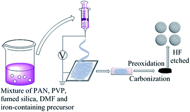
The Fe–N/MCS electrocatalysts were prepared by electrospinning and subsequent thermal treatment. In a typical process, the precursor solution was prepared by adding 0.43 g of fumed silica, 0.50 g of PVP, 0.50 g of PAN and a certain amount of iron-containing precursors in 9 g of DMF, followed by magnetic stirring for 24 h. (The addition of different iron-containing precursors follows the rule that the molar ratio of iron in the precursors to PAN is the same. On the basis of this rule, the addition of iron nitrate nonahydrate is 181 mg, the addition of ferric chloride hexahydrate is 121 mg, the addition of ferrocene is 83 mg and that of iron triacetylacetonate is 158 mg, respectively). Then, the solution was sucked into a plastic syringe and electrospun. The applied voltage, distance, and flow rate were controlled at 12 kV, 15 cm, and 0.05 ml h−1 during electrospinning with the temperature and the relative humidity of 25 °C and 38%, respectively. The microfiber was received on the Al foil as the collector.The prepared polymer microfiber was preoxidized by a heat treatment in a muffle at 220 °C under air for 120 min. Then, the polymer microfiber was heated up to 800 °C under nitrogen atmosphere with a heating rate of 2 °C min−1 and maintained the temperature for 120 min. After cooling down to room temperature, the catalyst was etched by 10 wt% HF solution for 6 h. Then, it was washed by deionized water until pH = 7. Finally, the catalyst was dried at 60 °C in the vacuum oven overnight. The catalyst was designated as Fe–N/MCS-X (X is the weight of different iron sources added). According to the rule that the amount of iron atom in the different iron precursor is the same. The samples of iron nitrate nonahydrate, ferric chloride hexahydrate, ferrocene and ferric triacetylacetone as the iron sources were designated as Fe–N/MCS-181, Fe–N/MCS-121, Fe–N/MCS-83 and Fe–N/MCS-158, respectively.
2.3 Physical characteristics
The images of all the electrocatalysts were characterized by scanning electron microscopy (SEM, JEOL2100F, Japan) and transmission electron microscopy (TEM, Talos F200X G2, China). The phase composition analyses of all the catalysts were tested by X-ray diffraction (XRD, Bruker, German, APLX-DUO) with Cu Kα radiation (λ = 1.5418 Å) radiation over the working voltage of 40 kV and the current of 40 mA. The scanning rate and the step size was 6° min−1 and 0.02°, respectively. X-ray photoelectron spectroscopy (XPS) analyses were carried out on an AXIS Ultra DLD X-ray photoelectron spectrometer system equipped with Al Kα radiation as the excitation source to analyze the chemical species and bonding nature of the catalysts. Raman spectra were obtained on a Thermo Fisher H31XYZE-US with an excitation laser of 532 nm. The specific surface areas were calculated by N2 adsorption/desorption isotherms through the Brunauere–Emmette–Teller (BET) method on the instrument of ASAP-2460. The pore size distribution was determined by the adsorption branches of the isotherms using Barrett–Joyner–Halenda (BJH) model.2.4 Electrochemical measurements
All the electrochemical tests about oxygen reduction reaction were carried out on an Autolab PGSTAT302 (Metrohm) through a three-electrode cell with a glassy carbon (GC) electrode as working electrode, Pt wire as counter electrode, and Ag/AgCl (3.0 M KCl) as reference electrode.The electrocatalyst ink was prepared by ultrasonically dispersing 1.0 mg of the electrocatalyst powder in the mixture consisting of 10.0 μL of Nafion solution as binder, 200.0 μL of ethanol and deionized water as dispersant for 30 min. Then, 4 μL catalyst ink was pipetted on the working electrode and dried in air.
Cyclic voltammetry (CV) and linear sweep voltammetry (LSV) were tested in 0.1 M KOH aqueous solution. LSV rotating speed ranges from 400 to 2000 rpm with a scan rate of 10 mV s−1. The chronoamperometry and methanol tolerance (3 M CH3OH) experiments were tested under 0.35 V at 1600 rpm.
The electron transfer number (n) was calculated by the Koutecky–Levich (K–L) equation:
| 1/J = 1/JL + 1/JK = 1/(Bω1/2) + 1/JK | (1) |
| JK = nFkC0 | (2) |
| B = 0.2nFC0(D0)2/3ν−1/6Jk = nFkC0 | (3) |
![[thin space (1/6-em)]](https://www.rsc.org/images/entities/char_2009.gif) 485C mol −1), C0 is the bulk concentration of O2 (1.2 × 10⁻⁶ mol cm−3), D0 is the diffusion coefficient of O2 in electrolytes (1.9 × 10⁻⁵ cm2 s−1), ν is the kinematic viscosity of the electrolyte (0.01 cm2 s−1) and k is the electron-transfer rate constant. The coefficient 0.2 is adopted when the unit of rotational speed is rpm.
485C mol −1), C0 is the bulk concentration of O2 (1.2 × 10⁻⁶ mol cm−3), D0 is the diffusion coefficient of O2 in electrolytes (1.9 × 10⁻⁵ cm2 s−1), ν is the kinematic viscosity of the electrolyte (0.01 cm2 s−1) and k is the electron-transfer rate constant. The coefficient 0.2 is adopted when the unit of rotational speed is rpm.
3. Results and discussion
The Fe–N/MCS electrocatalysts were synthesized by electrospinning and two-step thermal treatment, as shown in Fig. 1. The mesospheres were preoxidized and calcinated at 220 °C and 800 °C, respectively. According to SEM results (Fig. 2 a–d), it can be seen that four catalysts, Fe–N/MCS-181 (a), Fe–N/MCS-121 (b), Fe–N/MCS-83 (c) and Fe–N/MCS-158 (d), have spherical morphology with diameter between 2 to 7 μm. In comparison, Fe–N/MCS-181 (a) and Fe–N/MCS-121 (b) have complete spherical morphology than Fe–N/MCS-83 (c) and Fe–N/MCS-158 (d). To some extent, the destruction of mesospheres can lead the decrease of active sites of catalysts and the influence of reaction mass transfer, which may affect the catalytic performance of oxygen reduction. From TEM images, Fig. 2(e)–(h), all catalysts have the porous structure.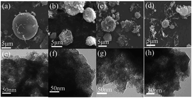 | ||
| Fig. 2 SEM and TEM images of Fe–N/MCS-181 (a and e), Fe–N/MCS-121 (b and f), Fe–N/MCS-83 (c and g), Fe–N/MCS-158 (d and h). | ||
N2 isotherm adsorption/desorption was used to calculate the surface area and porosity of the electrocatalysts. The results are shown in Fig. 3a, it can be seen that the four catalysts have typical IV-type curves, which proves that the Fe–N/MCS catalysts have obvious mesoporous structure. After calculation, the specific surface areas of Fe–N/MCS-181, Fe–N/MCS-121, Fe–N/MCS-83, Fe–N/MCS-158 catalysts and SiO2 are 212 m2 g−1, 197 m2 g−1, 221 m2 g−1, 193 m2 g−1 and 279 m2 g−1, respectively. Fig. 3b shows the pore size distribution of the catalysts at 10 and 35 nm and SiO2 at 35 nm. The pore size distribution at 35 nm is caused by etching silica template, while the pore size at 10 nm is may caused by the degradation of polyvinylpyrrolidone at high temperature. At the same time, sufficient mesopores could greatly add the density of active sites, which would benefit the ORR.18,19
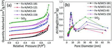 | ||
| Fig. 3 (a) Nitrogen adsorption–desorption isotherm and (b) pore size distribution of the Fe–N/MCS catalysts and SiO2. | ||
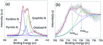
XPS was characterized to determine the content and the types of iron and nitrogen in four catalysts. The results of Fe–N/NCS-181 and other samples are shown in Fig. 4 and ESI (see Table S1 and Fig. S1†). It can be seen that N 1s and Fe 2p peaks appeared in the spectra of four catalysts. From Table S1,† it can be found that among the four catalysts, the content of iron in Fe–N/MCS-181 catalyst is up to 0.13%. And then, to further explore the catalytic active sites of the catalysts, Fe 2p and N 1s were studied. The results were shown in Fig. 4 (a) and S1(a, c and e).† It can be seen that the N 1s is divided into four peaks, which correspond to pyridine nitrogen (398.6 eV), pyrrole nitrogen (400.5 eV), graphite nitrogen (401.1 eV) and nitric oxide (405.1 eV).20–26 Due to pyrrole nitrogen contains lone-pair electron, it is easy to form active bonds with iron and promote oxygen reduction.27 According to Fig. 4(b) and S1(b, d and f),† 712 eV of Fe2+ 2p3/2 and 725 eV of Fe3+ 2p1/2 could be found. In accordance to XPS results, the content of Fe2+ in all catalysts is higher, which indicates that it is more conducive to form the Fe2+–N4 active sites, and more conducive to the catalytic process of oxygen reduction.
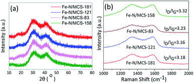
XRD and Raman measurements were carried out to study the formation of iron and carbon in catalysts. Fig. 5a is the XRD results of different catalysts. It can be found that there are characteristic diffraction peaks of (002) and (100) belonging to carbon in four catalysts near 2θ = 25° and 44°. These two peaks indicate that carbon exists in an amorphous form.28 In addition, there was no characteristic diffraction peak of iron.
Combining with SEM images, iron in the four catalysts were highly dispersed or existed in amorphous structure. Raman spectroscopy can usually characterize the graphitization degree or defect degree of carbon. From Fig. 5b, it can be seen that there are two large peaks near 1350 and 1580 cm−1 for the four catalysts. The two peaks around 1350 and 1580 cm−1 are represented to the D band and G band, respectively.29,30 The ratio of D band to G band (ID/IG) indicates the defect degree of carbon materials. From Fig. 5b, it can be found that the value of ID/IG of the four catalysts is very high, which is 3.18, 3.16, 3.23 and 3.32, respectively. The high value of ID/IG indicates that the catalysts are disordered and have a large number of defective sites, which is consistent with the results of amorphous carbon shown by XRD. The existence of such active sites will facilitate oxygen adsorption and thus promote ORR.
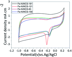
The electrochemical tests of catalysts are aimed at verifying the conjecture. CV results are shown in Fig. 6. As shown in the picture, the peak values of Fe–N/MCS-83, Fe–N/MCS-158, Fe–N/MCS-121 and Fe–N/MCS-181 is −0.183 V, −0.221 V, −0.158 V and −0.149 V, respectively. Among them, Fe–N/MCS-181 has better peak position. It indicates that Fe–N/MCS-181 could have the better ORR performance. However, considering characterization results of other catalysts, the reason why they have not good ORR performance than Fe–N/MCS-181. One is that the content of iron and Fe–N in other catalysts are less than Fe–N/MCS-181. Or the other aspect is that the destruction morphology of Fe–N/MCS-121, Fe–N/MCS-83, Fe–N/MCS-158 is more serious than Fe–N/MCS-181.
To further compare the ORR performance of four catalysts, LSV tests were carried out. Fig. S2† is the LSV test results. For comparison, commercial Pt/C was tested under the same condition. Its results were recorded in the Fig. 7. From the pictures, it can be seen that Fe–N/MCS-181 has the most positive initial potential and half-wave potential among the iron series catalysts. In the Fig. S3 and Table S2 (see in ESI†), it can be seen that the electron transfer number of Fe–N/MCS-181 is 4. The initial potential of Fe–N/MCS-181 is −0.018 V and the initial potential of commercial Pt/C is −0.01 V, respectively. The difference between them is only 8 mV. The half-wave potential of Fe–N/MCS-181 is −0.145 V, while commercial Pt/C is −0.180 V. And initial potential and half-wave potential of other catalysts have a bigger difference than Fe–N/MCS-181 and Pt/C. The results indicate that Fe–N/MCS-181 is a good catalyst for ORR. The initial potential, half-wave potential, limiting current density and electron transfer number of the four catalysts are shown in Table S2 (see in ESI†). Comparison of alkaline ORR performance between Fe–N/MCS-181 and some non-noble metal catalysts from recent literatures and the results are listed in Table S3 (see in ESI†). It can be seen that the catalyst in this work has certain performance advantages, but the activity is not the best. This may be related to its structure and type of active ingredients. Follow-up work can be further studied in detail.
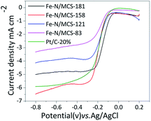 | ||
| Fig. 7 LSV curves of the Fe–N/MCS catalysts and Pt/C in O2 saturated 0.1 M KOH with a scan rate of 10 mV s−1. | ||
As shown in Fig. 8(a), the current retention percentages of Fe–N/MCS-181 and Fe–N/MCS-121 in alkaline media are 86.4% and 84.2%, which is better than commercial Pt/C (83.4%). In addition, methanol tolerance of the catalysts was tested under the same test conditions. As shown in Fig. 8(b) and S4 (see in ESI†), after adding 3 M methanol, the current density of Fe–N/MCS catalysts had no obvious change. While commercial Pt/C decreased sharply. These results confirm that Fe–N/MCS, especially Fe–N/MCS-181, has excellent durability, methanol tolerance and good effect on the application of fuel cells.
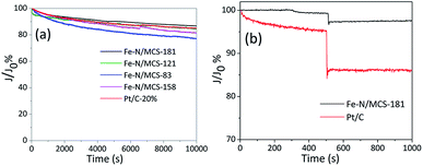 | ||
| Fig. 8 (a) Chronoamperometric responses of the Fe–N/MCS catalysts in O2 saturated 0.1 M KOH (b) chronoamperometric responses of Fe–N/MCS-181 and Pt/C with 3 M methanol. | ||
4. Conclusions
In summary, Fe–N/MCS electrocatalysts were successfully fabricated by electrospinning method and two thermal-step treatment. And compared with commercial Pt/C, the Fe–N/MCS electrocatalysts were tested ORR performances. Those results indicated that Fe–N/MCS electrocatalysts showed excellent electrocatalytic activity for the ORR in alkaline electrolytes. Among them, ferric nitrate nonahydrate as the source of iron doped N–C spheres (Fe–N/MCS-181) has the better ORR activity than other catalysts and commercial Pt/C. The paper not only provides a prospective ORR catalyst but also provides a novel point of view for the design and synthesis of metal-nitrogen-carbon catalysts for a variety of applications, such as sensors, batteries, and supercapacitors.Conflicts of interest
The authors declare that they have no competing interests.Acknowledgements
This project was financially supported by the National Nature Science Fundation of China (51573090). Meanwhile, this work was also got help from Shanghai Hydrogen Technology Co., Ltd. and the State Key Laboratory of Fluorinated Functional Membrane Material.Notes and references
- A. Serov, K. Artyushkova and P. Atanassov, Adv. Energy Mater., 2014, 4, 919–926 CrossRef.
- Z. M. Cui, L. Li, A. Manthiram and J. B. Goodenough, J. Am. Chem. Soc., 2015, 137, 7278–7281 CrossRef CAS PubMed.
- G. Nam, J. Park, C. Min, P. Oh, S. Park, G. K. Min, N. Park, J. Cho and J. S. Lee, ACS Nano, 2015, 9, 6493–6501 CrossRef CAS PubMed.
- J. Zhang, Z. Zhao, Z. Xia and L. Dai, Nat. Nanotechnol., 2015, 10, 444–452 CrossRef CAS PubMed.
- R. Bashyam and P. Zelenay, Nature, 2006, 443, 63–66 CrossRef CAS PubMed.
- C. W. Tsai, M. H. Tu, C. J. Chen, T. F. Huang, R. S. Liu, W. R. Liu, M. Y. Lo, Y. M. Peng, L. Zhang, J. J. Zhang, D. S. Shy and X. K. Xing, RSC Adv., 2011, 1, 1349–1357 RSC.
- Y. Liu, B. Huang, X. Zhang and X. Huang, J. Power Sources, 2019, 412, 125–133 CrossRef CAS.
- H. Tan, J. Tang, J. Kim, Y. V. Kaneti, Y. M. Kang, Y. Sugahara and Y. Yamauchi, J. Mater. Chem. A, 2019, 7, 1380–1393 RSC.
- L. Lin, Q. Zhu and A.-W. Xu, J. Am. Chem. Soc., 2014, 136, 11027–11033 CrossRef CAS.
- S.-J. Kim, J. Mahmood, C. Kim, G.-F. Han, S.-W. Kim, S. M. Jung, G. Zhu, J. J. DeYoreo, G. Kim and J.-B. Baek, J. Am. Chem. Soc., 2018, 140, 1737–1742 CrossRef CAS.
- Y. Hu, J. O. Jensen, W. Zhang, L. N. Cleemann, W. Xing, N. J. Bjerrum and Q. F. Li, Angew. Chem., Int. Ed., 2014, 53, 3675–3679 CrossRef CAS PubMed.
- F. Jaouen, V. Goellner, M. Lefevre, J. Herranz, E. Proietti and J. P. Dodelet, Electrochim. Acta, 2013, 87, 619–628 CrossRef CAS.
- J. Sen Li, S. L. Li, Y. J. Tang, M. Han, Z. H. Dai, J. C. Bao and Y. Q. Lan, Chem. Commun., 2015, 51, 2710–2713 RSC.
- M. Xiao, J. Zhu, L. Feng, C. Liu and W. Xing, Adv. Mater., 2015, 27, 2521–2527 CrossRef CAS.
- W. F. Chen, C. H. Wang, K. Sasaki, N. Marinkovic, W. Xu, J. T. Muckerman, Y. Zhu and R. R. Adzic, Energy Environ. Sci., 2013, 6, 943–951 RSC.
- A. P. Kishan and E. M. Cosgriff-Hernandez, J. Biomed. Mater. Res., Part A, 2017, 105, 2892–2905 CrossRef CAS PubMed.
- S. Cavaliere, S. Subianto, S. I. Savych, D. J. Jones and J. Rozière, Energy Environ. Sci., 2011, 4, 4761–4785 RSC.
- Q. L. Zhu, W. Xia, L. R. Zheng, R. Zou, Z. Liu and Q. Xu, ACS Energy Lett., 2017, 2, 504–511 CrossRef CAS.
- Q. Cheng, S. Han, K. Mao, C. Chen, L. Yang, Z. Zou, M. Gu, Z. Hu and H. Yang, Nano Energy, 2018, 52, 485–493 CrossRef CAS.
- E. J. Biddinger and U. S. Ozkan, J. Phys. Chem. C, 2010, 114, 15306–15314 CrossRef CAS.
- N. P. Subramanian, X. Li, V. Nallathambi, S. P. Kumaraguru, H. Colon-Mercado, G. Wu, J.-W. Lee and B. N. Popov, J. Power Sources, 2009, 188, 38–44 CrossRef CAS.
- Z. Luo, S. Lim, Z. Tian, J. Shang, L. Lai, B. MacDonald, C. Fu, Z. Shen, T. Yu and J. Lin, J. Mater. Chem., 2011, 21, 8038–8044 RSC.
- K. A. Kurak and A. B. Anderson, J. Phys. Chem. C, 2009, 113, 6730–6734 CrossRef CAS.
- Y. Hou, Z. Wen, S. Cui, S. Ci, S. Mao and J. Chen, Adv. Funct. Mater., 2015, 25, 872–882 CrossRef CAS.
- F. Li, G.-F. Han, H.-J. Noh, S.-J. Kim, Y. Lu, H. Y. Jeong, Z. Fu and J.-B. Baek, Energy Environ. Sci., 2018, 11, 2263–2269 RSC.
- Y. Dong, Y. Deng, J. Zeng, H. Song and S. Liao, J. Mater. Chem. A, 2017, 5, 5829–5837 RSC.
- S. Z. Li, Y. Y. Hu, Q. Xu, J. Sun, B. Hou and Y. P. Zhang, J. Power Sources, 2012, 213, 265–269 CrossRef CAS.
- Z. Y. Wang, F. Li, N. S. Ergang and A. Stein, Carbon, 2008, 46, 1702–1710 CrossRef.
- T. Kyotani, N. Sonobe and A. Tomita, Nature, 1988, 331, 331–333 CrossRef.
- M. A. Pimenta, G. Dresselhaus, M. S. Dresselhaus, L. G. Cancado, A. Jorio and R. Saito, Phys. Chem. Chem. Phys., 2007, 9, 1276–1291 RSC.
Footnote |
| † Electronic supplementary information (ESI) available. See DOI: 10.1039/c9ra08951a |
| This journal is © The Royal Society of Chemistry 2020 |

