
 Open Access Article
 This Open Access Article is licensed under a Creative Commons Attribution-Non Commercial 3.0 Unported Licence
Boron-doped few-layer graphene nanosheet gas sensor for enhanced ammonia sensing at room temperature†
Shubhda Srivastavaab,
Shubhendra K. Jainab,
Govind Gupta ab,
T. D. Senguttuvan*ab and
Bipin Kumar Gupta*ab
ab,
T. D. Senguttuvan*ab and
Bipin Kumar Gupta*ab
aCSIR-National Physical Laboratory, Dr K S Krishnan Road, New Delhi, 110012, India. E-mail: tdsen@nplindia.org; bipinbhu@yahoo.com
bAcademy of Scientific and Innovative Research (AcSIR), CSIR-National Physical Laboratory Campus, Dr K S Krishnan Road, New Delhi 110012, India
First published on 3rd January 2020
Abstract
Heteroatom doping in graphene is now a practiced way to alter its electronic and chemical properties to design a highly-efficient gas sensor for practical applications. In this series, here we propose boron-doped few-layer graphene for enhanced ammonia gas sensing, which could be a potential candidate for designing a sensing device. A facile approach has been used for synthesizing boron-doped few-layer graphene (BFLGr) by using a low-pressure chemical vapor deposition (LPCVD) method. Further, Raman spectroscopy has been performed to confirm the formation of graphene and XPS and FESEM characterization were carried out to validate the boron doping in the graphene lattice. To fabricate the gas sensing device, an Si/SiO2 substrate with gold patterned electrodes was used. More remarkably, the BFLGr-based sensor exhibits an extremely quick response for ammonia gas sensing with fast recovery at ambient conditions. Hence, the obtained results for the BFLGr-based gas sensor provide a new platform to design next-generation lightweight and fast gas sensing devices.
1. Introduction
Graphene has now become a vibrant superstar and the most popular choice in the field of two dimensional (2D) materials research with a few years of extremely deep study after its discovery.1 Graphene has a unique structure with very interesting properties, such as electrical, mechanical, and thermal, and it has been largely explored in electronics,1–3 composites,4,5 sensors,6–8 solar cells,9,10 and electrode materials.11,12 Nowadays, the focus has shifted to the tailoring of its properties and, more specifically, the tuning of its physicochemical properties has opened a new path for the development of graphene-based applications in the energy,13 sensing,14 biomedicine,15 and photovoltaic areas.16 The experimental manipulation of the graphene lattice usually involves the alteration of the carbon sp2 structure by introducing defects in the form of doping. Particularly, the chemical doping of heteroatoms in the graphene lattice provides an efficient route to alter its chemical as well as electronic properties. The basic graphene honeycomb lattice is altered to a hetero-atom-doped graphene structure by the substitution of carbon atoms with any other compatible atom from the periodic table. Recently, many studies have been reported in the literature based on heteroatom doping in the graphene lattice.17,18 The possible dopants incorporated in the graphene lattice could be B, N, S, P, Se, O, Si, I, and many metals too. Out of the different available dopants, the two closest neighbors of carbon in the periodic table, i.e. boron (B) and nitrogen (N), have definitely attracted the attention of many researchers, owing to their similar atomic sizes. Nitrogen as a dopant in graphene for inducing n-type conductivity has already been explored widely in terms of its synthesis,19–22 characterization23,24 and applications.25–27 On the other hand, boron, with less electronegativity than carbon, can induce p-type conductivity in graphene on doping. There are only a few experimental studies28–33 that demonstrate the properties and applications of boron-doped graphene, which further re-ignites researchers worldwide for more experimental exploration in this area. Apart from these, a lot of theoretical work has been carried out to demonstrate its potential properties and applications. As per these studies, B atoms embedded in a graphene lattice have properties that make it suitable for use in field-effect transistors,34 hydrogen storage,35 and Li-ion batteries.36 In this continuation, numerous theoretical and experimental studies37–44 have shown that boron-doped graphene could also be explored as a very promising candidate for gas sensing applications, apart from the many potential applications mentioned above. Boron doping can effectively enhance the surface reactivity of graphene for adsorbing various gas molecules by introducing a local high charge density.In the current scenario, air pollution is a significant issue faced by our sphere.45 The presence of various toxic gaseous pollutants (such as NH3, NOx, CO, and CO2) in air, which are continuously released from industry, automobiles, and domestic activities, is causing serious impacts on both human health and the environment.46 Ammonia (NH3) is one of these toxic pollutants that is widely used in various industries and can injure the skin, eyes and even the respiratory system when the concentration in the air is above 25 ppm.47 As per the OSHA (Occupational Safety and Health Administration), the exposure limit for ammonia is 50 ppm (8 hours per day) and the maximum exposure tolerance is 500 ppm.48 Hence, it is a demand of today's world to continuously research and develop new materials for highly sensitive sensors for ammonia detection. There are various reports in the literature49–51 on ammonia sensing and in a few recent articles52–54 some new materials for ammonia sensing have been studied. Furthermore, there are several reports on graphene-based ammonia sensors,55,56 which encourage the tailoring of the graphene structure for better sensors. In this regard, Zhang et al.37 concluded in their study that B-doped graphene could be the most suitable choice for NH3 sensing. Lv et al.42 and Ahmadi et al.43 showed experimentally that B-doped graphene could be a strong new material for NH3 sensing.
Here, to experimentally explore the gas sensing properties of boron-doped graphene, we synthesized boron-doped few-layer graphene (BFLGr) nanosheets through a low-pressure chemical vapor deposition (LPCVD) method and then tested them for NH3 detection at room temperature. The pure graphene (PFLGr) and BFLGr nanosheets were synthesized using ethanol as the carbon source and boron powder as the boron source. It was observed that the BFLGr nanosheets were much more sensitive and selective for NH3 at room temperature. The LPCVD-grown graphene nanosheets were further characterized by Raman spectroscopy, FESEM, TEM, and X-ray photoelectron spectroscopy (XPS).
2. Experimental
2.1 Synthesis of graphene nanosheets
In the present study, pure (PFLGr) and boron-doped graphene nanosheets (BFLGr) were grown on 0.025 μm thick 99.8% pure copper foil (procured from Alfa Aesar) using ethanol as the carbon source and boron powder as the boron source. Firstly, a certain amount of boron powder was ultra-sonicated in ethanol for 45 min and then spray-coated on a 2 × 2 cm2 piece of copper foil. After air drying, the foil was kept in the constant heating zone of a 2.5′′ horizontal quartz tube of an LPCVD furnace while ethanol was kept in a round-bottomed flask, which was then connected to the quartz tube. The system was then vacuumed to the initial pressure of 0.5 torr and then the furnace was heated to 950 °C with a constant flow of hydrogen (H2) and argon (Ar) and the tube pressure was maintained at 12.5 torr. As soon as the temperature was reached, the ethanol vapor was allowed to flow in the tube and the total tube pressure was maintained at 15.4 torr. After growth for 5 min, the ethanol vapor was stopped and the furnace was opened to cool the sample in the continuous flow of H2 and Ar. For the PFLGr nanosheet synthesis, the same conditions were used except the boron powder coating. The LPCVD system arrangement for the BFLGr nanosheet growth is shown in Fig. 1.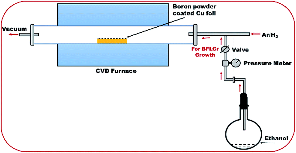 | ||
| Fig. 1 Low-pressure chemical vapor deposition (LPCVD) setup for the synthesis of BFLGr nanosheets. | ||
2.2 Sensor device fabrication
Firstly, a thin layer of poly-(methyl methacrylate) (PMMA) was spin-coated on the grown graphene nanosheets on copper foil at about 3000 rpm for 60 s and were kept for 1–2 minutes for air drying. Next, the PMMA-coated graphene/copper foil was floated in a 3![[thin space (1/6-em)]](https://www.rsc.org/images/entities/char_2009.gif) :1 ratio solution of water and nitric acid to etch the copper foil. After complete etching of the copper, the graphene film with PMMA was scooped out on the Si/SiO2 substrate pre-patterned with Au electrodes, the Si/SiO2 and TEM grids were cleaned, and further cleaning was done by repeatedly dipping in DI water and IPA and then drying under N2. Finally, the substrates were dipped in hot acetone to remove the PMMA layer.
:1 ratio solution of water and nitric acid to etch the copper foil. After complete etching of the copper, the graphene film with PMMA was scooped out on the Si/SiO2 substrate pre-patterned with Au electrodes, the Si/SiO2 and TEM grids were cleaned, and further cleaning was done by repeatedly dipping in DI water and IPA and then drying under N2. Finally, the substrates were dipped in hot acetone to remove the PMMA layer.
The film on the Si/SiO2 substrate with Au electrodes was then used as a sensor device and also for I–V measurements.
The other transferred nanosheets were further characterized by Raman spectroscopy (InVia Raman Microscope, Renishaw), field emission scanning electron microscopy (FESEM), energy-dispersive X-ray spectroscopy (EDX), UV-1800 Shimadzu spectrophotometer, high-resolution transmission electron microscopy (HRTEM), and X-ray photoelectron spectroscopy (XPS, Scienta Omicron). A laser with a 514 nm excitation wavelength was used for Raman measurements. The HRTEM images were taken using a Tecnai G2 S-Twin scanning transmission electron microscope. The XPS measurements were performed using an Al Kα X-ray source (energy 1486.6 eV) with a pass energy of 100 eV for the survey scans and 40 eV for the core-level spectral scans. Before the measurements, the spectrometer was calibrated using the photoemission lines of Au (Au 4f7/2 = 83.9 eV, with reference to the Fermi level) and Cu (Cu 2p3/2 = 932.5 eV). The binding energy scale was calibrated with the C 1s line (284.6 eV) from the carbon contamination layer.
2.3 Gas sensing measurements
The gas sensing measurements were performed using an indigenously developed sensor setup made from stainless steel with a 200 ml volume at CSIR-National Physical Laboratory, New Delhi, India. During the measurement, the continuous change in resistance with time was recorded with an Agilent B2901A Precision Source meter with a constant applied voltage of 0.5 V. Fig. 2 shows the complete sensor setup. By controlling the injection procedure, the concentration of the target gas NH3 was varied from 16 to 256 ppm. Before each testing cycle, the testing chamber was evacuated using a rotary pump to the base pressure of ∼10−3 torr. The gas sensing ability was studied in terms of sensor response, selectivity, and stability. The gas sensor response here is defined as S (%) = [{(Ra − Rg)/Ra} × 100] where Ra and Rg are the resistances of the sensor in air and gas, respectively.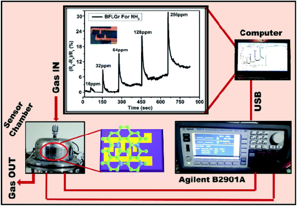 | ||
| Fig. 2 Schematic diagram of indigenously developed gas sensor setup. | ||
3. Results and discussion
3.1 Morphological and structural study
After transferring the graphene on to the Si/SiO2 substrate, an optical microscope image of the BFLGr nanosheet was taken. Fig. 3a shows the optical image of an atomically thin large-area BFLGr nanosheet.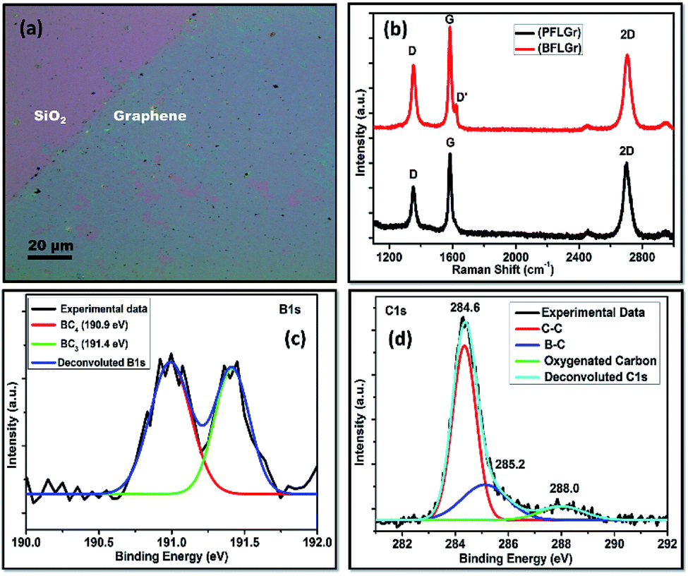 | ||
| Fig. 3 (a) Optical microscope image of transferred BFLGr sheet on Si/SiO2 substrate. (b) Raman spectra of PFLGr and BFLGr nanosheets. Deconvoluted (c) B 1s and (d) C 1s XPS spectra of BFLGr nanosheet. | ||
Raman spectroscopy is one of the most powerful techniques for identifying carbon-related materials and is best suited for studying the number of layers, doping, and defects of graphene.57,58 Fig. 3b exhibits the typical Raman spectra of the PFLGr and BFLGr nanosheets. For PFLGr, the two characteristic bands G and 2D corresponding to the stretching vibration of sp2 bonded carbon and the second-order vibrations activated by double resonance, respectively,58,59 are centered at 1581 cm−1 and 2699 cm−1. Another band, i.e. the D band at 1350 cm−1, is attributed to the defect-induced double resonance Raman feature in graphene60 and usually indicates disordered carbon atoms and wrinkles in the graphitic lattice.58,59 In contrast, an enhanced D band at 1353 cm−1 along with a D′ band on the shoulder of the G band at 1623 cm−1 can be observed in the BFLGr. This band may be attributed to the intravalley double resonance scattering process in doped graphene where the defects provide the momentum for satisfying the resonance process.58,61 The enhanced intensity of the D band in the BFLGr sheet could be because of the defects introduced by the in-plane doping of boron atoms in the graphene lattice. Furthermore, boron doping alters the Fermi surface of graphene, which in turn shifts the Raman band positions. All of the predominant G and 2D bands, positions, and intensity ratios are given in Table S1.† The D band to G band intensity ratio (ID/IG) can be used to evaluate the defect density in graphene nanosheets.59 This increased ratio of ID/IG (0.84) for BFLGr as compared to PFLGr (0.69) indicates the presence of higher defects in the BFLGr nanosheet after boron doping. Compared to that of PFLGr, both the G (1584 cm−1) and 2D (2705 cm−1) bands are upshifted by 3 cm−1 and 6 cm−1, respectively, in BFLGr while the I2D/IG ratio decreases from PFLGr to BFLGr. The occurrence of the D′ band with increased D band intensity, the upshifts in the positions of the G and 2D bands, and the decrease in I2D/IG ratio for the BFLGr nanosheet support p-type doping in BFLGr.62
X-ray photoelectron spectroscopy (XPS) analysis was done to get a clearer view of the different chemical compositions and bonding of boron in the BFLGr film on the Si/SiO2 substrate, as shown in Fig. 3c and d. The two prominent peaks at 190.9 eV and 284.4 eV can be identified as B 1s and C 1s, respectively.63–65 Fig. 3c shows the B 1s core-level spectra and its deconvolution into two sub-peaks. The peak with a binding energy of 191.4 eV could be attributed to boron atoms with the local environment of ideal BC3 type B–C bonding,63 which is higher than those reported for elemental boron (187.1 eV). An increase in the binding energy value for the BFLGr film indicates that the boron atoms have substituted for carbon atoms in the sp2 hybridized carbon network.64 The other broad peak at a binding energy of 190.9 eV could be assigned to BC4-type B–C binding. Sometimes BC4-type binding may go with the defects present in the graphene network, the functional edges of graphene sheets64 and edge oxidized boron and it could also be further confirmed that the D band in the Raman spectrum of BFLGr (Fig. 3b) is enhanced with respect to that for PFLGr. Based on the XPS intensity measurements, the content of boron was calculated to be 4.93%. Table 1 shows the ratio of elements present in the BFLGr sheet. Moreover, the boron binding configurations for BC3 and BC4 were also calculated and came out to be almost the same as 49.9% and 50.1%, respectively (Table 2). The prominent peak at 284.6 eV corresponds to the C 1s core-level spectrum of the BFLGr, sheet which can further be deconvoluted into three peaks. The more intense peak at 284.6 eV can be assigned to graphitic sp2 carbon (C–C bonding) in BFLGr.66 The small peak at 285.2 eV may be assigned to B–C binding.42 Another peak at 288.0 eV could be related to oxygenated carbon.67 This small peak around 288.6 eV was also observed in the case of C 1s core level spectrum of PFLGr (Fig. S1†), which may arise due to the physisorption of oxygen on the graphene surfaces or could be related to graphene edge and defect oxidation. It could also be easily observed in nitrogen-doped graphene.68 Furthermore, the absence of a peak at 285.2 eV in PFLGr was observed, as shown in Fig. S1.†
| Sample | Carbon (C) (at%) | Boron (B) (at%) | Oxygen (O) (at%) |
|---|---|---|---|
| BFLGr | 74.8 | 4.9 | 20.3 |
| Sample | BC3 | BC4 | ||
|---|---|---|---|---|
| BE (eV) | Ratio (%) | BE (eV) | Ratio (%) | |
| BFLGr | 191.4 | 49.9 | 190.9 | 50.1 |
Transmission electron microscopy (TEM) was performed to visualize the microstructure and number of layers in the PFLGr and BFLGr nanosheets. The TEM images shown in Fig. 4a and c exhibit continuous and wrinkled graphene layers for the PFLGr and BFLGr nanosheets, respectively. According to the high-resolution TEM (HRTEM) images [Fig. 4b and d], PFLGr and BFLGr both are few-layered (5–6 layers), which is also supported by the I2D/IG ratio of Raman spectra (Table S1†). Fig. S2† shows the UV-vis transmittance of the BFLGr nanosheet transferred on the quartz substrate. The transmittance of B-doped graphene is similar to that of pristine graphene.69 The transmittance of single-layer graphene is ∼97.5% and decreases by 2.3% for each additional layer.70,71 Hence, few-layer graphene should have an optical transmittance of ∼86%, which well matches with the plot shown in Fig. S2† for BFLGr.
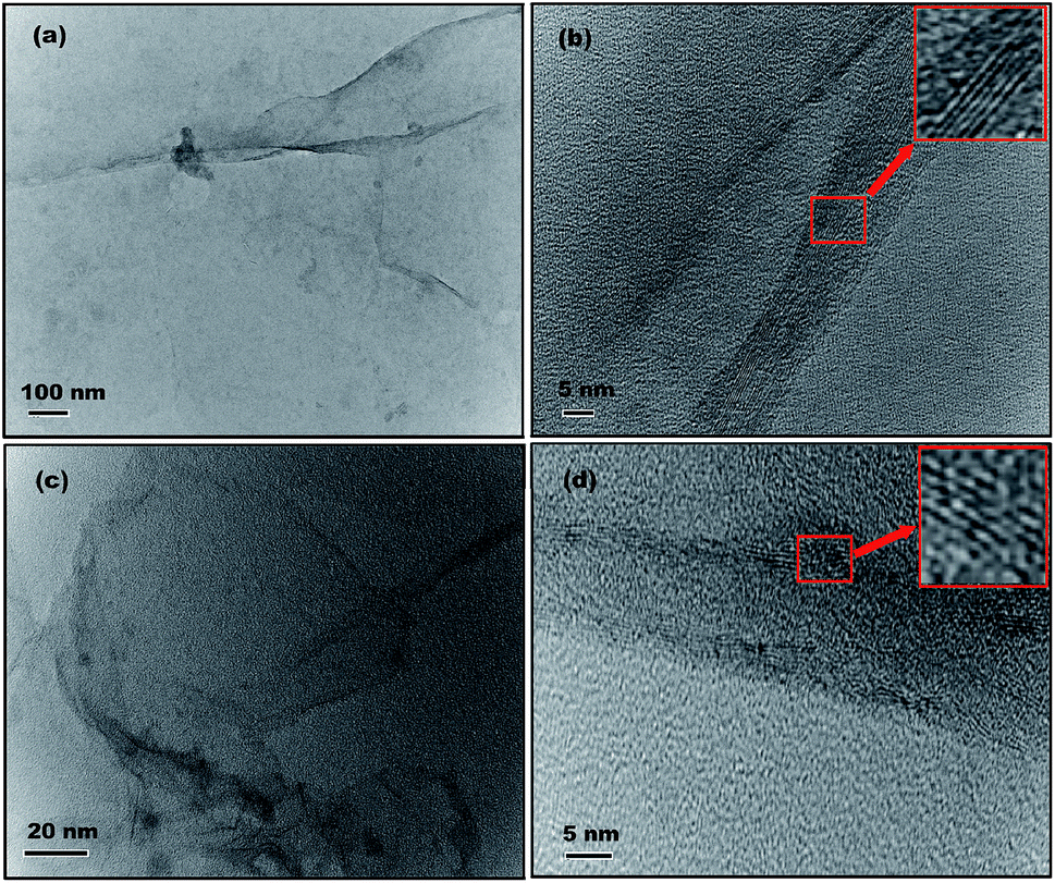 | ||
| Fig. 4 (a) & (c) TEM and (b) & (d) HRTEM images of the PFLGr and BFLGr nanosheets. The insets are the enlarged areas in red squares showing the number of layers of nanosheets. | ||
Fig. S3† shows the FESEM image of the BFLGr nanosheet along with the EDX spectrum. Fig. S3a† shows the sheet-like structure of BFLGr whereas in Fig. S3b† the EDX spectrum exhibits the presence of boron in the BFLGr sheet and hence supports the XPS results shown in Fig. 3c.
3.2 I–V characteristics
The I–V (current–voltage) characteristics of the PFLGr and BFLGr nanosheets were studied before and after gas adsorption in the voltage range of −0.5 V to 0.5 V. As shown in Fig. 5, the linear I–V curves of both the nanosheets show good ohmic contact between the nanosheets and the gold contacts. From Fig. 5, it can also be observed that due to an increased amount of defects and boron doping, the conductivity of BFLGr is decreased by 10.25 times from that of PFLGr and hence the resistance is increased in the voltage range of −0.1 V to 0.1 V. | ||
| Fig. 5 I–V characteristics of the PFLGr and BFLGr nanosheets. | ||
3.3 Gas sensing properties study
The gas sensing properties of both the sensors were studied by measuring the change in electrical resistance with time upon exposure to NH3 gas. All the measurements were performed at ambient conditions with a static72–74 flow of NH3. For every measurement cycle, the gas was injected in the test chamber and the change in the resistance with time was measured. Upon exposure to a reducing gas, i.e. NH3, there was an increase in the resistance, which shows the p-type sensing behavior of both of the sensors. The sensors were exposed to ambient conditions for recovery.Fig. 6a and b shows the sensing behavior of the PFLGr and BFLGr sensors in terms of sensor response versus time for different concentrations of NH3 gas ranging from 16 ppm to 256 ppm. It could be observed that for each cycle the sensor recovers to its original response value within just a few seconds of being exposed to ambient conditions. Fig. 6c and S4a† show the response–recovery cycle for the BFLGr and PFLGr sensors. Here, the BFLGr sensor shows a higher response and faster recovery as compared to the PFLGr sensor (Fig. S4a†). The response values for the BFLGr and PFLGr sensors were 8.92% and 2.64%, respectively, for 32 ppm of gas. This result implies that the boron doping in graphene improves the interaction of the nanosheets with the NH3 gas molecules.
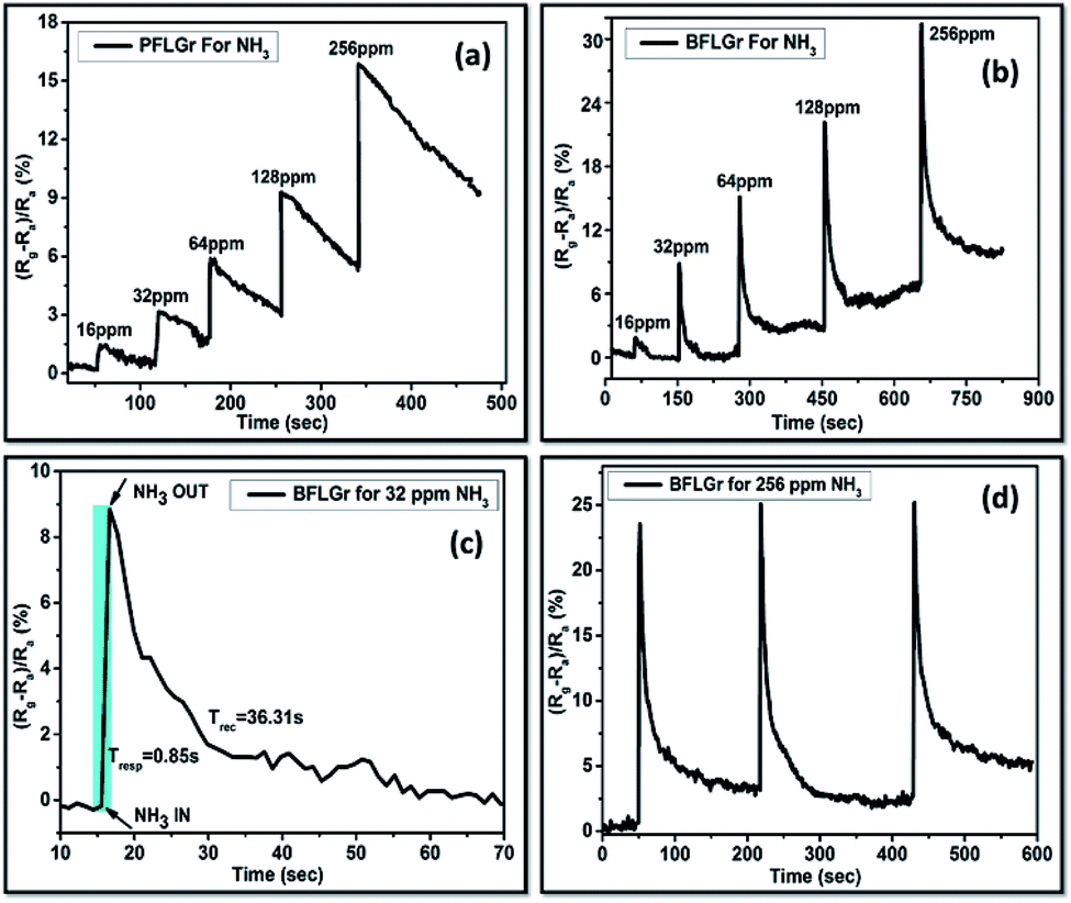 | ||
| Fig. 6 Response vs. time plots for (a) PFLGr and (b) BFLGr for 16 to 256 ppm of NH3. Response and recovery plot for the BFLGr sensor for 32 ppm of NH3 (c). Repeatability plot for BFLGr for 256 ppm of NH3 (d). | ||
The response time (Tresp) is defined as the time required to reach 90% of the response value and similarly the recovery time (Trec) is defined as the time required until 90% of the baseline is recovered.75 Here, the calculated response time (Tresp) for the BFLGr sensor was 0.85 s, which is much less as compared to the undoped PFLGr sensor (3.56 s), as shown in Fig. 6c and S4a,† while the recovery times (Trec) for the sensors were 36.31 s and 48.24 s, respectively.
As of now, very little research has been reported on ammonia gas sensing by boron-doped LPCVD graphene to the best of our knowledge.42,43 A table comparing the sensing performances of boron-doped CVD graphene sensors reported in the literature is given in Table S2.† In the present work, the main objective was to explore boron-doped CVD graphene for gas sensing application at room temperature, which has not yet been reported for few-layer boron-doped graphene at low ppm values of NH3. Moreover, in our work sensor recovery was achieved by exposing the sensors to ambient conditions, while in the work reported in the literature, UV42 and IR43 illumination have been used for sensor recovery. Concisely, our BFLGr sensor based on few-layer boron-doped LPCVD graphene exhibits a great response and fast recovery at room temperature for NH3 and could be a superb candidate for gas sensing application. To test the repeatability and reproducibility, the sensors were repeatedly exposed to 256 ppm of NH3 and three response–recovery cycles were recorded, as shown in Fig. 6d and S4b.† It can be clearly seen from the figures that the sensors are highly repeatable and reproducible for continuous exposure to gas and maintain the response.
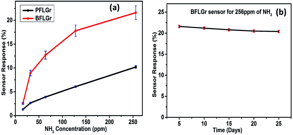
As shown in Fig. 7a, the change in the response value with increasing gas concentration was also plotted with error bars. The results indicate that the response of the sensors increases linearly with the increase in gas concentration. For the stability test, the response of the BFLGr sensor was measured continuously for 25 days for 256 ppm and for 10 days for 16 ppm of NH3. Fig. 7b and S5† show the corresponding plots of response vs. time in days for 256 ppm and 16 ppm, respectively. Both the plots exhibit the good stability of the proposed BFLGr sensor for both the high and low concentrations of NH3.
 | ||
| Fig. 7 (a) Response of sensors with error bars as a function of NH3 concentration in ppm. (b) Stability study of BFLGr sensor with error bars for 256 ppm of NH3 as a function of time in days. | ||
To determine the effects of interfering gases and chemical species, a selectivity test was performed for the BFLGr sensor. For this, the BFLGr sensor was exposed to some interferant gases at 256 ppm, including CO2, H2, and various volatile organic compounds (VOCs), such as acetone, ethanol, formaldehyde and toluene. The desired concentrations of CO2 and H2 were taken from calibrated cylinders and for the VOCs the desired concentrations were obtained by taking their calculated vapors in closed containers at room temperature. The test results shown in Fig. S6† show that the BFLGr sensor is highly selective for NH3. The high NH3 selectivity may be because of the different adsorption energies of the different gaseous species.37,76
3.4 Gas sensing mechanism
It is well known that the interaction between graphene and adsorbed gas molecules alters graphene's electronic properties through charge transfer and this interaction is extremely dependent on the graphene structure (doped/undoped), molecular adsorption configuration and adsorption energies.37 From all the results shown, it could be understood that both of the sensors exhibit p-type sensing behavior for NH3. This means that when NH3 is adsorbed on the sensing layer, it donates an electron to the sensing layer and hence alters its electronic properties by increasing the resistance. Now, the strength of this interaction will determine the response value for the PFLGr and BFLGr sensors. The adsorption mechanism for NH3 is more complicated than for other molecules and it shows different adsorption configurations on different graphene structures. The optimized adsorption structures of NH3/PFLGr and NH3/BFLGr are shown in Fig. 8.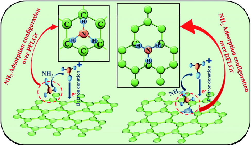 | ||
| Fig. 8 Schematic illustration of NH3 adsorption and proposed gas sensing mechanism of the PFLGr and BFLGr sensors. | ||
From Fig. 8, it can be seen that NH3 has a tripod configuration and the favorable adsorption configuration on the undoped PFLGr is with the three hydrogen atoms of NH3 pointing towards the graphene plane.37,77 As per reported theoretical calculations, this adsorption configuration gives an adsorption energy of −0.11 eV for pristine graphene, indicating weak adsorption, and −0.24 eV for graphene with some defects, indicating slightly stronger adsorption than pristine graphene.37 Here, in our case, as supported by the Raman spectra in Fig. 3b, the PFLGr sensor has some defects and hence the proposed adsorption configuration would give an adsorption energy of −0.24 eV. On the other hand, in the BFLGr sensor, NH3 will favorably attach to the B atom with the N atom pointing at the sheet, giving an adsorption energy of −0.50 eV.37 The adsorption energy for NH3 on BFLGr is much higher than on PFLGr. This higher adsorption energy is attributed to the strong interaction between the electron-deficient boron atom and the electron-offering N atom of the NH3 molecule. Zhang et al.37 in their theoretical research also calculated the adsorption energy of NH3 on nitrogen-doped graphene, which is −0.12 eV. It again shows a weak interaction between NH3 and N-doped graphene. Hence, based on the above calculations and theoretical results, it could be predicted that boron-doped graphene is the best choice for NH3 sensing, which well supports our results for the BFLGr sensor.
4. Conclusions
In summary, boron-doped/undoped few-layer graphene nanosheets were successfully synthesized using the LPCVD method, where ethanol and ethanol/boron powder were used as precursors. The synthesized boron-doped/undoped few-layer graphene nanosheets were confirmed by various characterization techniques (Raman, XPS and FESEM) and then successfully transferred on to a Si/SiO2 substrate to fabricate the boron-doped/undoped few-layer graphene gas sensing devices. Further, the fabricated sensing devices were examined with different concentrations of NH3 gas. The proposed BFLGr sensor is highly stable and has been successfully demonstrated for selective ammonia gas sensing. The performance of the fabricated device based on BFLGr exhibited very fast gas sensing response at ambient conditions, which provides an alternative choice for designing futuristic ultrathin, lightweight high-performance gas sensing devices.Conflicts of interest
There are no conflicts to declare.Acknowledgements
The authors wish to thank Dr D. K. Aswal (Director, N. P. L.), New Delhi. The authors also thank Mrs Shweta Sharma for performing the Raman spectroscopic measurements of the graphene sample, Mr Dinesh Singh for the HRTEM micrographs, and Mr Vipin Kumar for his support in the design of the sensing setup. Shubhda Srivastava would like to thank the Department of Science & Technology (Ministry of Science & Technology) for the financial assistance under the Women Scientist (SR/WOS-A/ET-49/2013) scheme.Notes and references
- K. S. Novoselov, A. K. Geim, S. V. Morozov, D. Jiang, Y. Zhang, S. V. Dubonos, I. V. Grigorieva and A. A. Firsov, science, 2004, 306, 666–669 CrossRef CAS PubMed.
- G. Eda, G. Fanchini and M. Chhowalla, Nat. Nanotechnol., 2008, 3, 270 CrossRef CAS PubMed.
- Y. Tang, C. S. Lee, Z. Chen, G. Yuan, Z. Kang, L. Luo, H. Song, Y. Liu, Z. He and W. Zhang, Nano Lett., 2009, 9, 1374–1377 CrossRef CAS PubMed.
- S. Stankovich, D. A. Dikin, G. H. Dommett, K. M. Kohlhaas, E. J. Zimney, E. A. Stach, R. D. Piner, S. T. Nguyen and R. S. Ruoff, nature, 2006, 442, 282 CrossRef CAS PubMed.
- M. A. Rafiee, J. Rafiee, Z. Wang, H. Song, Z.-Z. Yu and N. Koratkar, ACS Nano, 2009, 3, 3884–3890 CrossRef CAS PubMed.
- F. Schedin, A. Geim, S. Morozov, E. Hill, P. Blake, M. Katsnelson and K. Novoselov, Nat. Mater., 2007, 6, 652 CrossRef CAS PubMed.
- H. G. Sudibya, Q. He, H. Zhang and P. Chen, ACS Nano, 2011, 5, 1990–1994 CrossRef CAS PubMed.
- L. A. L. Tang, J. Wang and K. P. Loh, J. Am. Chem. Soc., 2010, 132, 10976–10977 CrossRef CAS PubMed.
- Z. Liu, Q. Liu, Y. Huang, Y. Ma, S. Yin, X. Zhang, W. Sun and Y. Chen, Adv. Mater., 2008, 20, 3924–3930 CrossRef CAS.
- Y. Wang, X. Chen, Y. Zhong, F. Zhu and K. P. Loh, Appl. Phys. Lett., 2009, 95, 209 Search PubMed.
- X. Wang, L. Zhi and K. Müllen, Nano Lett., 2008, 8, 323–327 CrossRef CAS.
- S. Bae, H. Kim, Y. Lee, X. Xu, J.-S. Park, Y. Zheng, J. Balakrishnan, T. Lei, H. R. Kim and Y. I. Song, Nat. Nanotechnol., 2010, 5, 574 CrossRef CAS PubMed.
- J. Liu, Y. Xue, M. Zhang and L. Dai, MRS Bull., 2012, 37, 1265–1272 CrossRef CAS.
- S. S. Varghese, S. Lonkar, K. Singh, S. Swaminathan and A. Abdala, Sens. Actuators, B, 2015, 218, 160–183 CrossRef CAS.
- D. Bitounis, H. Ali-Boucetta, B. H. Hong, D. H. Min and K. Kostarelos, Adv. Mater., 2013, 25, 2258–2268 CrossRef CAS PubMed.
- X. Huang, Z. Yin, S. Wu, X. Qi, Q. He, Q. Zhang, Q. Yan, F. Boey and H. Zhang, small, 2011, 7, 1876–1902 CrossRef CAS PubMed.
- H. Terrones, R. Lv, M. Terrones and M. S. Dresselhaus, Rep. Prog. Phys., 2012, 75, 062501 CrossRef PubMed.
- R. Lv and M. Terrones, Mater. Lett., 2012, 78, 209–218 CrossRef CAS.
- D. Wei, Y. Liu, Y. Wang, H. Zhang, L. Huang and G. Yu, Nano Lett., 2009, 9, 1752–1758 CrossRef CAS PubMed.
- B. Guo, Q. Liu, E. Chen, H. Zhu, L. Fang and J. R. Gong, Nano Lett., 2010, 10, 4975–4980 CrossRef CAS PubMed.
- C. Zhang, L. Fu, N. Liu, M. Liu, Y. Wang and Z. Liu, Adv. Mater., 2011, 23, 1020–1024 CrossRef CAS PubMed.
- Z. Jin, J. Yao, C. Kittrell and J. M. Tour, ACS Nano, 2011, 5, 4112–4117 CrossRef CAS PubMed.
- J. C. Meyer, S. Kurasch, H. J. Park, V. Skakalova, D. Künzel, A. Groß, A. Chuvilin, G. Algara-Siller, S. Roth and T. Iwasaki, Nat. Mater., 2011, 10, 209 CrossRef CAS PubMed.
- R. Lv, Q. Li, A. R. Botello-Méndez, T. Hayashi, B. Wang, A. Berkdemir, Q. Hao, A. L. Elías, R. Cruz-Silva and H. R. Gutiérrez, Sci. Rep., 2012, 2, 586 CrossRef PubMed.
- L. Qu, Y. Liu, J.-B. Baek and L. Dai, ACS Nano, 2010, 4, 1321–1326 CrossRef CAS PubMed.
- A. L. M. Reddy, A. Srivastava, S. R. Gowda, H. Gullapalli, M. Dubey and P. M. Ajayan, ACS Nano, 2010, 4, 6337–6342 CrossRef CAS PubMed.
- S. Srivastava, P. K. Kashyap, V. Singh, T. Senguttuvan and B. K. Gupta, New J. Chem., 2018, 42, 9550–9556 RSC.
- Q. Zhu, J. Yu, W. Zhang, H. Dong and L. Dong, J. Renewable Sustainable Energy, 2013, 5, 021408 CrossRef.
- L. Zhao, M. Levendorf, S. Goncher, T. Schiros, L. Palova, A. Zabet-Khosousi, K. T. Rim, C. Gutierrez, D. Nordlund and C. Jaye, Nano Lett., 2013, 13, 4659–4665 CrossRef CAS PubMed.
- H. Wang, Y. Zhou, D. Wu, L. Liao, S. Zhao, H. Peng and Z. Liu, small, 2013, 9, 1316–1320 CrossRef CAS PubMed.
- J. Gebhardt, R. Koch, W. Zhao, O. Höfert, K. Gotterbarm, S. Mammadov, C. Papp, A. Görling, H.-P. Steinrück and T. Seyller, Phys. Rev. B, 2013, 87, 155437 CrossRef.
- Z.-H. Sheng, H.-L. Gao, W.-J. Bao, F.-B. Wang and X.-H. Xia, J. Mater. Chem., 2012, 22, 390–395 RSC.
- X. Li, L. Fan, Z. Li, K. Wang, M. Zhong, J. Wei, D. Wu and H. Zhu, Adv. Energy Mater., 2012, 2, 425–429 CrossRef CAS.
- B. Huang, Phys. Lett. A, 2011, 375, 845–848 CrossRef CAS.
- Y. Zhou, X. T. Zu, F. Gao, J. Nie and H. Xiao, J. Appl. Phys., 2009, 105, 014309 CrossRef.
- Y. Liu, V. I. Artyukhov, M. Liu, A. R. Harutyunyan and B. I. Yakobson, J. Phys. Chem. Lett., 2013, 4, 1737–1742 CrossRef CAS PubMed.
- Y.-H. Zhang, Y.-B. Chen, K.-G. Zhou, C.-H. Liu, J. Zeng, H.-L. Zhang and Y. Peng, Nanotechnology, 2009, 20, 185504 CrossRef PubMed.
- M. D. Esrafili, Phys. Lett. A, 2019, 383, 1607–1614 CrossRef CAS.
- Y. Fujimoto, Nanomater. Nanotechnol., 2017, 7, 1–7 CAS.
- R. Miwa, T. B. Martins and A. Fazzio, Nanotechnology, 2008, 19, 155708 CrossRef CAS PubMed.
- I. Choudhuri, N. Patra, A. Mahata, R. Ahuja and B. Pathak, J. Phys. Chem. C, 2015, 119, 24827–24836 CrossRef CAS.
- R. Lv, G. Chen, Q. Li, A. McCreary, A. Botello-Méndez, S. Morozov, L. Liang, X. Declerck, N. Perea-López and D. A. Cullen, Proc. Natl. Acad. Sci., 2015, 112, 14527–14532 CrossRef CAS PubMed.
- S. Ahmadi and R. Afzalzadeh, Micro Nano Lett., 2018, 13, 363–368 CrossRef CAS.
- S. Turner, W. Yan, H. Long, A. J. Nelson, A. Baker, J. R. Lee, C. Carraro, M. A. Worsley, R. Maboudian and A. Zettl, J. Phys. Chem. C, 2018, 122, 20358–20365 CrossRef CAS.
- M. Kampa and E. Castanas, Environ. Pollut., 2008, 151, 362–367 CrossRef CAS PubMed.
- X.-d. Wang and O. S. Wolfbeis, Chem. Soc. Rev., 2014, 43, 3666–3761 RSC.
- B. Timmer, W. Olthuis and A. Van Den Berg, Sens. Actuators, B, 2005, 107, 666–677 CrossRef CAS.
- N. Roney and F. Llados, 2004.
- V. V. Quang, N. S. Trong, N. N. Trung, N. D. Hoa, N. V. Duy and N. V. Hieu, Anal. Lett., 2014, 47, 280–294 CrossRef CAS.
- B. Sakthivel and G. Nammalvar, J. Alloys Compd., 2019, 788, 422–428 CrossRef CAS.
- H. Fan, S. Han, Z. Song, J. Yu and H. E. Katz, Org. Electron., 2019, 67, 247–252 CrossRef CAS.
- D. Ziegler, A. Marchisio, G. Ercolino, S. Specchia and J.-M. Tulliani, Solid State Ionics, 2019, 337, 91–100 CrossRef CAS.
- H. Yin, C. Song, Z. Wang, H. Shao, Y. Li, H. Deng, Q. Ma and K. Yu, Nanomaterials, 2019, 9, 317 CrossRef CAS PubMed.
- Z. Deng, G. Meng, X. Fang, W. Dong, J. Shao, S. Wang and B. Tong, J. Alloys Compd., 2019, 777, 52–58 CrossRef CAS.
- H. Zhang, L. Fan, H. Dong, P. Zhang, K. Nie, J. Zhong, Y. Li, J. Guo and X. Sun, ACS Appl. Mater. Interfaces, 2016, 8, 8652–8661 CrossRef CAS PubMed.
- M.-S. Park, K. H. Kim, M.-J. Kim and Y.-S. Lee, Colloids Surf., A, 2016, 490, 104–109 CrossRef CAS.
- R. Beams, L. G. Cançado and L. Novotny, J. Phys.: Condens. Matter, 2015, 27, 083002 CrossRef PubMed.
- A. C. Ferrari, J. Meyer, V. Scardaci, C. Casiraghi, M. Lazzeri, F. Mauri, S. Piscanec, D. Jiang, K. Novoselov and S. Roth, Phys. Rev. Lett., 2006, 97, 187401 CrossRef CAS PubMed.
- M. Pimenta, G. Dresselhaus, M. S. Dresselhaus, L. Cancado, A. Jorio and R. Saito, Phys. Chem. Chem. Phys., 2007, 9, 1276–1290 RSC.
- X. Wang, X. Li, L. Zhang, Y. Yoon, P. K. Weber, H. Wang, J. Guo and H. Dai, science, 2009, 324, 768–771 CrossRef CAS PubMed.
- L. Malard, M. Pimenta, G. Dresselhaus and M. Dresselhaus, Phys. Rep., 2009, 473, 51–87 CrossRef CAS.
- A. Das, S. Pisana, B. Chakraborty, S. Piscanec, S. K. Saha, U. V. Waghmare, K. S. Novoselov, H. R. Krishnamurthy, A. K. Geim and A. C. Ferrari, Nat. Nanotechnol., 2008, 3, 210 CrossRef CAS PubMed.
- T. Shirasaki, A. Derré, M. Ménétrier, A. Tressaud and S. Flandrois, Carbon, 2000, 38, 1461–1467 CrossRef CAS.
- T. Wu, H. Shen, L. Sun, B. Cheng, B. Liu and J. Shen, New J. Chem., 2012, 36, 1385–1391 RSC.
- Y. A. Kim, K. Fujisawa, H. Muramatsu, T. Hayashi, M. Endo, T. Fujimori, K. Kaneko, M. Terrones, J. Behrends and A. Eckmann, ACS Nano, 2012, 6, 6293–6300 CrossRef CAS PubMed.
- A. Siokou, F. Ravani, S. Karakalos, O. Frank, M. Kalbac and C. Galiotis, Appl. Surf. Sci., 2011, 257, 9785–9790 CrossRef CAS.
- C. Mattevi, G. Eda, S. Agnoli, S. Miller, K. A. Mkhoyan, O. Celik, D. Mastrogiovanni, G. Granozzi, E. Garfunkel and M. Chhowalla, Adv. Funct. Mater., 2009, 19, 2577–2583 CrossRef CAS.
- Y. Xue, B. Wu, L. Jiang, Y. Guo, L. Huang, J. Chen, J. Tan, D. Geng, B. Luo and W. Hu, J. Am. Chem. Soc., 2012, 134, 11060–11063 CrossRef CAS PubMed.
- E. Romani, D. Larrude, M. da Costa, G. Mariotto and F. Freire, J. Nanomater., 2017, 2017, 9298637 Search PubMed.
- W. Li, G. Cheng, Y. Liang, B. Tian, X. Liang, L. Peng, A. H. Walker, D. J. Gundlach and N. V. Nguyen, Carbon, 2016, 99, 348–353 CrossRef CAS.
- T. Lin, F. Huang, D. Wan, H. Bi, X. Xie and M. Jiang, Nanoscale, 2013, 5, 5847–5853 RSC.
- J. Huang, K. Yu, C. Gu, M. Zhai, Y. Wu, M. Yang and J. Liu, Sens. Actuators, B, 2010, 147, 467–474 CrossRef CAS.
- V. Kumar, S. Srivastava and K. Jain, Sens. Transducers J., 2009, 101, 60 CAS.
- L. Zhu, Y. Jia, G. Gai, X. Ji, J. Luo and Y. Yao, Sens. Actuators, B, 2014, 190, 134–140 CrossRef CAS.
- C. Liewhiran and S. Phanichphant, Sensors, 2007, 7, 185–201 CrossRef CAS.
- B. Huang, Z. Li, Z. Liu, G. Zhou, S. Hao, J. Wu, B.-L. Gu and W. Duan, J. Phys. Chem. C, 2008, 112, 13442–13446 CrossRef CAS.
- S. M. Seyed-Talebi, J. Beheshtian and M. Neek-Amal, J. Appl. Phys., 2013, 114, 124307 CrossRef.
Footnote |
| † Electronic supplementary information (ESI) available. See DOI: 10.1039/c9ra08707a |
| This journal is © The Royal Society of Chemistry 2020 |