 Open Access Article
The synthesis of nano-sized TS-1 zeolites under rotational crystallisation conditions can inhibit anatase formation
Xing Wei ,
Yu-Jia Wang,
Tie-Qiang Ren,
Hai-Yan Wang* and
Min Wei
Liaoning Key Laboratory of Petroleum & Chemical Industry, Liaoning Shihua University, Fushun 113001, P. R. China. E-mail: fswhy@126.com
First published on 3rd January 2020
Abstract
Hydrothermal synthesis is a typical method for the preparation of TS-1. In the current study, agitation was introduced during the crystallisation stage, and nano-sized TS-1 with little anatase TiO2 was successfully synthesised in a short time (1–8 h). Furthermore, under rotational crystallisation conditions, a series of TS-1 samples was prepared with different crystallisation times, and the products obtained were investigated as catalysts for the oxidative desulfurisation of thiophene from a model fuel. All samples were characterised utilising X-ray diffraction (XRD), scanning electron microscopy (SEM), N2-adsorption, ultraviolet-visible (UV-Vis) spectroscopy and Fourier-transform infrared (FT-IR) spectroscopy techniques. It was found that under rotational crystallisation conditions, nano-sized TS-1 could be synthesised in a short time that had improved efficiency for the oxidative desulfurisation reaction of thiophene in comparison with TS-1 synthesised by static crystallisation for 24 h.
Introduction
With the advancement of technology and economic development, both the production and use of motor vehicles have increased dramatically. Goldman Sachs predicts that global car sales will reach 120 million in 2030, with a holding of 1.5 billion. In addition, BP forecasts that in 2035 there will be close to 1.8 billion vehicles in the world, of which electric vehicles (including pure electric and plug-in hybrid electric vehicles) will constitute a total of 71 million, accounting for approximately 4% of global car ownership.1 The environmental pollution from motor vehicle exhausts is becoming increasingly alarming, and the pollution caused by sulfur compounds in fuels is the focus of environmental management. The presence of organic sulfur compounds in gasoline and diesel can cause problems such as flameout in the use of automotive internal combustion engines. Moreover, the combustion of organic sulfur compounds in the fuel releases sulfur dioxide, which results in acid rain and haze, further contributing to environmental pollution. Chemicals of this type can also lead to catalyst poisoning in automobile exhaust gas purification devices, and consequently, to excessive emission of nitrogen oxides. With a view to controlling the hazards of sulfides in automobile exhausts, governments have successively formulated strict fuel standards to control the environmental pollution caused by sulfur from that source. The catalytic hydrodesulfurisation process is a conventional method for industrially removing organic sulfides from oil;2 however, it also reduces the content of olefins and aromatic hydrocarbons during deep hydrogenation. As a result, the octane number of the gasoline is lowered. Furthermore, the equipment used for this process requires a large investment and is often associated with high operating costs. By increasing the amount of hydrogen and prolonging the contact time of the reaction, the efficiency of catalytic hydrodesulfurisation can be improved, and ultra-deep desulfurisation can be realised. Nevertheless, this approach will inevitably lead to problems such as reduced service life of the catalyst and further increase of the operating costs. Compared with hydrodesulfurisation, oxidative desulfurisation has the advantages of low energy consumption and simplicity. Notably, the catalytic oxidative desulfurisation system utilising H2O2 as the oxidant is particularly environmentally friendly and results in the production of water as the final product.3,4 TS-1 has been used as a catalyst in the desulfurisation of fuel oil by H2O2 oxidation. The introduction of titanium metal gives a unique catalytic oxidation activity and the sulfur content can be reduced to just 10 ppm. In addition, TS-1 exhibits good activity and selectivity in the catalytic oxidation of organic sulfides and is easy to separate, recover and regenerate without affecting the quality of the fuel.5,6 In recent years, significant research on oxidative desulfurisation of TS-1 has led to the development of methods to effectively remove sulfides from fuel oil.7 In 1983, Taramasso reported the first classical synthesis of TS-1 by a hydrothermal approach.8 The most crucial step in this method is to carefully control the synthesis of the starting gel. Since the hydrolysis rate of the titanium source in the solution is much faster than that of the silicon source, the former rapidly polymerises to form titanium anatase TiO2. This not only leads to the loss of the titanium source, which needs to become a part of the skeleton, but also causes inefficient decomposition of H2O2, which is unfavourable for the catalytic performance.9,10 The TS-1 synthesis conditions are usually harsh and alcohol addition is typically necessary to protect the titanium source.11 Thangaraj et al. have modified the classical synthesis procedure. In their work, the source of titanium was dissolved in isopropyl alcohol to avoid the instantaneous hydrolysis of Ti-alkoxide to TiO2. (once TiO2 is formed, it is no longer available for incorporation into the framework).12 Zhang et al. found that owing to the effect of diffusion, TS-1 with a particle size of 0.2–0.3 μm showed a higher catalytic reaction activity than TS-1 with a particle size of approximately 10 μm. They found that higher silicon concentration, lower OH− concentration and high solid concentration are favourable for the synthesis of small-grained TS-1 and successfully synthesised TS-1 with a particle size below 100 nm.13 S. Gontier et al. used amorphous SiO2 as the source and successfully synthesised TS-1 with a particle size of approximately 800 nm.14 The high price of tetrapropylammonium hydroxide (TPAOH) also limits the widespread use of TS-1. Müller et al. first reported the successful synthesis of TS-1 by replacing the expensive TPAOH with the inexpensive tetrapropylammonium bromide, TPABr, as a template for the synthesis of TS-1.15 Zuo et al. prepared a mother liquor in advance, and then successfully synthesised TS-1 using inexpensive TPABr as a template agent, silica sol as a silicon source and TiCl4 as a titanium source.16 As a consequence of using molecular sieves containing a microporous structure, the macromolecular reactants are too large to come into contact with the active sites in the pores. Two distinctive strategies can be employed to resolve this issue. The first involves changing the reaction conditions to obtain nano-sized crystals and to eliminate the diffusion limitation of the micropores. This can increase the external specific surface area and the exposure of the active sites of Ti, thereby increasing the catalytic activity.4,17 The second strategy consists of creating mesopores or macropores in the TS-1 crystal structure.18–20 Regardless of the method employed to increase the mesopores in TS-1, it is challenging to ensure that the prepared TS-1 has uniform properties, and the industrial production remains difficult. Therefore, optimising the reaction conditions promises to be the most effective way to directly obtain TS-1 with high catalytic performance. It is generally believed that zeolites with good crystallinity exhibit improved catalytic performance. In the report by Bai et al., it was revealed that TS-1 with incomplete crystallisation displays better catalytic effects in oxidative desulfurisation reactions.21 Moreover, Zhang et al. demonstrated that agitation conditions increased the rate of entry of titanium into the TS-1 framework and avoided the formation of anatase TiO2 in the system.22In the present work, we employed stirring during the short TS-1 hydrothermal crystallisation, which resulted in the successful synthesis of nano-sized TS-1 with little anatase TiO2. The prepared sample contains a large number of micropores and has a large specific surface area. TS-1 synthesised under rotational crystallisation conditions exhibited improved catalytic performance in the oxidative desulfurisation reaction compared with statically synthesised TS-1. Hence, our report provides a new approach for the preparation of TS-1 for oxidative desulfurisation reaction.
Experimental section
Synthesis
![[thin space (1/6-em)]](https://www.rsc.org/images/entities/char_2009.gif) :
:![[thin space (1/6-em)]](https://www.rsc.org/images/entities/char_2009.gif) 0.025TiO2
0.025TiO2![[thin space (1/6-em)]](https://www.rsc.org/images/entities/char_2009.gif) :
:![[thin space (1/6-em)]](https://www.rsc.org/images/entities/char_2009.gif) 0.3TPAOH
0.3TPAOH![[thin space (1/6-em)]](https://www.rsc.org/images/entities/char_2009.gif) :
:![[thin space (1/6-em)]](https://www.rsc.org/images/entities/char_2009.gif) 50H2O. TPAOH was mixed with deionised water and stirred vigorously for 15 min. Subsequently, TBOT was added dropwise and the suspension was stirred for 1 h prior to the addition of TEOS. The reaction mixture was further stirred for 2 h. The initial gel was transferred and crystallised at 170 °C into a stainless steel kettle with agitation for 1–8 h. The rate of revolutions was set to 120 rpm. The samples were extracted in condensed water to immediately stop crystallisation. The mixture obtained was filtered, washed with deionised water, dried at 90 °C overnight, and calcined at 550 °C for 6 h. The resulting samples were named TS-1-xh, where x denotes the crystallisation time in hours. For comparison, TS-1-24h was crystallised under static conditions with the same molar composition as the TS-1-xh samples by using a conventional oven.
50H2O. TPAOH was mixed with deionised water and stirred vigorously for 15 min. Subsequently, TBOT was added dropwise and the suspension was stirred for 1 h prior to the addition of TEOS. The reaction mixture was further stirred for 2 h. The initial gel was transferred and crystallised at 170 °C into a stainless steel kettle with agitation for 1–8 h. The rate of revolutions was set to 120 rpm. The samples were extracted in condensed water to immediately stop crystallisation. The mixture obtained was filtered, washed with deionised water, dried at 90 °C overnight, and calcined at 550 °C for 6 h. The resulting samples were named TS-1-xh, where x denotes the crystallisation time in hours. For comparison, TS-1-24h was crystallised under static conditions with the same molar composition as the TS-1-xh samples by using a conventional oven.Infrared absorption spectroscopy was carried out utilising a Thermo Fisher Nicolexis 50 type Fourier-transform infrared spectrometer. The samples were mixed with potassium bromide powder and compressed, and the scanning range was set to 400–4000 cm−1 with a resolution of 4 cm−1. Each scan was performed 32 times.
The microscopic morphology was evaluated by means of a Japanese Hitachi SU8010 field emission scanning electron microscope. Energy dispersive X-ray (EDX) spectrometry was used to image and analyse the silicon-to-titanium ratio of the catalysts.
The textural properties were examined by N2 air-suction desorption on a Quantachrome Autosorb-IQ2-MP automatic static physical adsorption instrument. The total specific surface area, St, was calculated by the multi-point Brunauer, Emmett and Teller (BET) method (P/P0 = 0.005–0.3). The surface area, Sm, was obtained by the t-plot method. The total pore volume, Vt, was measured at P/P0 = 0.99, whereas the micropore volume, Vm, was obtained using the De Boer method. Lastly, the average pore diameter was calculated as 4Vt/St.
Ultraviolet-visible (UV-Vis) diffuse reflectance spectroscopy was employed to characterise the morphology of the titanium species in the TS-1 molecular sieve as well as its chemical environment. The scanning range was 200–800 nm.
![[thin space (1/6-em)]](https://www.rsc.org/images/entities/char_2009.gif) :
:![[thin space (1/6-em)]](https://www.rsc.org/images/entities/char_2009.gif) V(water)
V(water)![[thin space (1/6-em)]](https://www.rsc.org/images/entities/char_2009.gif) :
:![[thin space (1/6-em)]](https://www.rsc.org/images/entities/char_2009.gif) V(H2O2)
V(H2O2)![[thin space (1/6-em)]](https://www.rsc.org/images/entities/char_2009.gif) :
:![[thin space (1/6-em)]](https://www.rsc.org/images/entities/char_2009.gif) m(molecular sieve) = 15 mL
m(molecular sieve) = 15 mL![[thin space (1/6-em)]](https://www.rsc.org/images/entities/char_2009.gif) :
:![[thin space (1/6-em)]](https://www.rsc.org/images/entities/char_2009.gif) 15 mL
15 mL![[thin space (1/6-em)]](https://www.rsc.org/images/entities/char_2009.gif) :
:![[thin space (1/6-em)]](https://www.rsc.org/images/entities/char_2009.gif) 0.05 mL
0.05 mL![[thin space (1/6-em)]](https://www.rsc.org/images/entities/char_2009.gif) :
:![[thin space (1/6-em)]](https://www.rsc.org/images/entities/char_2009.gif) 0.15 g. Following the addition of the starting materials at 60 °C, the upper oil phase was sampled every 30 min. The separated liquid phase was added to deionised water to remove the water-soluble products (sulfoxide, sulfone, etc.). The upper oil phase was then separated and the sulfur content was determined using a TSN-5000 analyser.
0.15 g. Following the addition of the starting materials at 60 °C, the upper oil phase was sampled every 30 min. The separated liquid phase was added to deionised water to remove the water-soluble products (sulfoxide, sulfone, etc.). The upper oil phase was then separated and the sulfur content was determined using a TSN-5000 analyser.Evaluation of the index of thiophene oxidation removal was performed using the following formula:
| X = (c0 − ct)/c0 × 100% | (1) |
Results and discussion
Characterizations
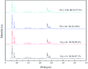
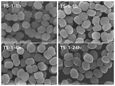
Fig. 1 illustrates the X-ray diffraction (XRD) patterns of TS-1 zeolites synthesised under different conditions and reaction times. The main characteristic diffraction peaks of 2θ = 7.8°, 8.8°, 23.0°, 23.9° and 24.4° could be observed in the XRD patterns of all the samples, which correspond to the MFI topology structure, indicating the phase purity of the samples. The single diffraction peaks at 2θ = 24.5° and 29.3° are due to the Ti-atom inside the zeolite framework.24 It can be seen that the crystallinity of TS-1 obtained under rotational crystallisation for 1 h is close to that produced by static crystallisation for 24 h. This clearly suggests that the crystallisation rate of TS-1 is accelerated under rotational conditions. Since a large number of crystal nuclei are generated using this approach, TS-1 exhibiting a complete MFI structure can be synthesised in a short time in the spin crystallisation process.Scanning electron microscopy (SEM) images of the TS-1 samples are shown in Fig. 2. It can be observed that when the crystallisation time is just 1 h, the TS-1 obtained presents as small particles with rough surfaces. However, as the crystallisation time is increased, corners begin to appear. Moreover, with further increase of the crystallisation time, the edges of the TS-1 particles become sharp at the same as this occurs for TS-1-24h. It can also be seen from the images that as the crystallisation time is extended after 1 h, the crystal size remains nearly the same and changes occur mainly in the surface morphology.
The N2 adsorption–desorption isotherms and density functional theory (DFT) pore size distribution of all samples are shown in Fig. 3, and a summary of the properties of TS-1 appears in Table 1. The N2 adsorption–desorption isotherms of all samples are type I isotherms. At a lower relative pressure, significant jumps can be observed in the isotherms, suggesting that the sample is a typical microporous material.25 The numerical relationship between the amount of adsorption at the lower relative pressure is in the order TS-1-24h > TS-1-1h > TS-1-4h > TS-1-8h. This observation can be deciphered from the pore size distribution image, where TS-1 with short crystallisation time displays a more microporous structure. Under rotational crystallisation conditions, the crystallisation time is prolonged and the total pore volume and specific surface area of the sample are reduced. On the other hand, the statically crystallised TS-1 has a larger pore volume and specific surface area.
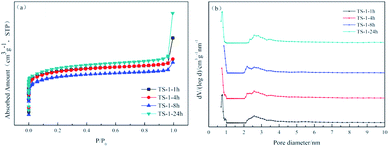 | ||
| Fig. 3 The N2 adsorption–desorption isotherms (a) and DFT pore size distributions (b) of TS-1 samples. | ||
| Sample | Si/Ti | Sm (m2 g−1) | Sext (m2 g−1) | St (m2 g−1) | Vm (cm3 g−1) | Vt (cm3 g−1) | Dp (nm) | Th conv. (%) |
|---|---|---|---|---|---|---|---|---|
| a The micropore surface area Sm, external surface area Sext, total surface area St, micropore volume Vm and total pore volume Vt, average pore diameter Dp as determined from nitrogen sorption analysis. Si/Ti is the molar ratio nSi/nTi of the TS-1. | ||||||||
| TS-1-1h | 31.8 | 434 | 38 | 472 | 0.19 | 0.34 | 2.9 | 86.6 |
| TS-1-4h | 39.1 | 419 | 45 | 464 | 0.18 | 0.25 | 2.2 | 85.2 |
| TS-1-8h | 40.2 | 382 | 34 | 416 | 0.16 | 0.24 | 2.3 | 83.5 |
| TS-1-24h | 42.0 | 448 | 50 | 498 | 0.20 | 0.45 | 3.6 | 82.9 |
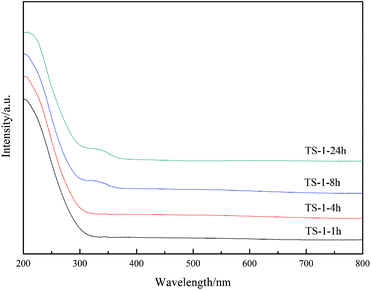
UV-visible spectroscopy is a common means of characterising the presence of titanium in the backbone of TS-1.26,27 The non-framework titanium of TS-1 exhibits an absorption peak at 260–280 nm,28,29 while the absorption peak at 310–330 nm is attributed to anatase TiO2.17 As seen in Fig. 4, all samples exhibit an absorption peak at 210 nm; therefore, the titanium successfully enters the framework. Furthermore, as the crystallisation time increases to 8 h, the absorption peak of anatase TiO2 appears in the system. As expected, an absorption peak at 330 nm is present for the TS-1-24h sample. Because of the inconsistent rate of hydrolysis of the titanium and the silicon sources, a peak at 330 nm was unavoidably observed in other reports,24,30,31 which describe that anatase TiO2 forms easily during the TS-1 synthesis. Under the conditions of rotational crystallisation, the rate of entry of titanium into the TS-1 framework appears to be accelerated, and the formation of anatase TiO2 can be effectively avoided. Nonetheless, an absorption peak at 330 nm was observed in the TS-1-8h sample, indicating that prolonging the crystallisation time may cause the form of titanium to transition from framework titanium to anatase TiO2.
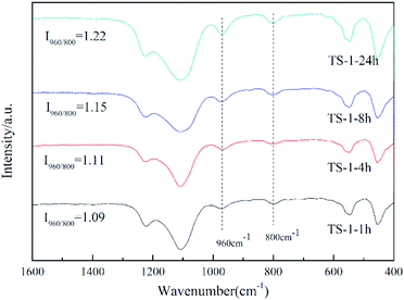
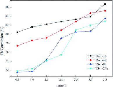
Fourier-transform infrared (FT-IR) spectroscopy was used to further investigate the Ti species in the zeolite framework (Fig. 5). The band at 800 cm−1 is attributed to the typical MFI topology,32 and that silicalite-1 has no characteristic peak at 960 cm−1 (ref. 30 and 33) is considered to be evidence that titanium enters the TS-1 framework. The intensity of the peak at 960 cm−1 relative to the peak at 800 cm−1 (I960/800) is usually used to semi-quantify the framework titanium content.34,35 The higher the value of I960/800, the higher the titanium content of the framework. According to this, the framework titanium content can be roughly presented in the order TS-1-24h > TS-1-8h > TS-1-4h > TS-1-1h. Combining this result with the data for catalytic oxidative desulfurisation, it can be concluded that the catalytic performance does not improve as a consequence of the increase of the framework titanium content.
Catalytic desulfurisation performance
Catalytic oxidative desulfurisation activity is demonstrated in Fig. 6. For TS-1-1h and TS-1-4h, the crystallisation time is short, and the oxidative desulfurisation performance is excellent at the initial stage of the reaction. In addition, the final thiophene conversion is also exceptional. For example, for TS-1-8h and TS-1-24h, the thiophene conversion as well as other analytical data are alike, which indicates that TS-1 crystallised for 8 h under rotational conditions has the same oxidative desulfurisation performance as TS-1 obtained from static crystallisation for 24 h. Moreover, the desulfurisation effect of both is significantly lower than the effect of TS-1-1h and TS-1-4h. This result may be due to the presence of small amounts of anatase TiO2, which results in inefficient decomposition of H2O2. Thasaneeya et al. reported that by increasing the catalyst contact time, the removal efficiency of thiophene could be increased to 84%. However, the conversion is relatively more efficient for a feed with higher thiophene concentration; 84% thiophene removal can be achieved from a feed with 3000 ppm thiophene, compared with 75% from that with 1000 ppm thiophene.36 In comparison, in our work, TS-1 is crystallised in a very short time under the rotational conditions, it takes less time to reach the same thiophene conversion ratio and the absolute value of the thiophene content in model oil can be reduced to a very low level. The oxidative desulfurisation reaction data confirm that the synthesis of TS-1 under dynamic synthesis conditions can significantly shorten the crystallisation time and avoid the formation of anatase TiO2. It is generally necessary to add an alcohol in the preparation of the gel to prevent excessive hydrolysis of the titanium source. This method simplifies the synthesis step of TS-1 and improves its efficiency.According to all of the characterisation results, agitation during crystallisation allows fast synthesis of TS-1 and inhibits the formation of anatase TiO2. Electron micrographs show that after 1 h of crystallisation, the grain size only changes marginally but the surface morphology is altered. Moreover, the BET data reveal that a long crystallisation time leads to a decrease in specific surface area and pore volume. However, the comparison TS-1-1h and TS-1-24h suggests that high specific surface area and pore volume do not result in improved catalytic desulfurisation. In addition, the value of the atomic ratio of silicon and titanium in the sample is noteworthy: the smaller the value, the higher the titanium content. The Si/Ti initially placed in the material was 40, whereas the detected Si/Ti value was only 31.8, indicating that titanium preferentially entered the TS-1 skeleton in the early stage of crystallisation. By comparison, in the study by Bai et al., the initial feed ratio Si/Ti was also 40, but the final TS-1 product Si/Ti value reached 73–160.21 The Si/Ti value increases with increasing crystallisation time, which may be due to the migration of titanium from the surface of the TS-1 to the inside of the skeleton. Infrared data also demonstrate that the increase in the catalytic titanium content of the framework does not lead to better performance. This outcome proves that the titanium on the surface of the skeleton is the determinant of the catalytic oxidative desulfurisation reaction. This means that the synthesis of TS-1 does not have to pursue a complete degree of crystallinity or pore structure, but rather the distribution of titanium on the framework and a reduction in the formation of anatase TiO2. Lastly, by changing the crystallisation conditions, it is possible to provide a new strategy for improving the catalytic performance of TS-1.
Conclusions
In summary, the introduction of agitation during the crystallisation process significantly shortens the crystallisation time and inhibits the formation of anatase TiO2. The characterisation results revealed that the TS-1 catalyst grows uniformly during the crystallisation process. During the initial stage of crystallisation, the framework titanium concentrates on the surface of the TS-1 skeleton, and the crystallisation time increases the in situ migration of active framework skeleton titanium. Prolonging the crystallisation time may also result in the transition of tetracoordinated framework titanium to the anatase TiO2 form.Conflicts of interest
There are no conflicts to declare.Acknowledgements
This work was supported by the Scientific Research Project of the Provincial Education Department [L2017LQN008].Notes and references
- J.-T. Yan, International oil economy, 2018 Search PubMed.
- A. Stanislaus, A. Marafi and M. S. Rana, Catal. Today, 2015, 153, 1–68 CrossRef.
- B. Puértolas, A. K. Hill, T. García, B. Solsona and L. Torrente-Murciano, Catal. Today, 2015, 248, 115–127 CrossRef.
- P. De Filippis and M. Scarsella, Energy Fuels, 2003, 17, 1452–1455 CrossRef CAS.
- G. Ye, Y. Sun, D. Zhang, W. Zhou, C. Lancelot, A. Rives, C. Lamonier and W. Xu, Microporous Mesoporous Mater., 2018 Search PubMed , S1387181118302774.
- V. Hulea, F. Fajula and J. Bousquet, J. Catal., 2001, 198, 179–186 CrossRef CAS.
- C. G. Piscopo, J. Tochtermann, M. Schwarzer, D. Boskovic, R. Maggi, G. Maestri and S. Loebbecke, React. Chem. Eng., 2018, 3, 13–16 RSC.
- M. Taramasso, G. Perego and B. Notari, 1983.
- N. Wilde, J. Prech, M. Pelz, M. Kubu, J. Cejka and R. Glaser, Catal. Sci. Technol., 2016, 6, 7280–7288 RSC.
- Y. Zuo, M. Liu, T. Zhang, C. Meng, X. Guo and C. Song, Chemcatchem, 2015, 7, 2660–2668 CrossRef CAS.
- A. Tuel, Catal. Lett., 1998, 51, 59–63 CrossRef CAS.
- A. Thangaraj and S. Sivasanker, J. Chem. Soc., Chem. Commun., 1992, 12, 943–950 CAS.
- G. Zhang, J. Sterte and B. Schoeman, J. Chem. Soc., Chem. Commun., 1995, 22, 2259–2260 RSC.
- S. Gontier and A. Tuel, Zeolites, 16, 184–195 CrossRef CAS.
- U. Müller and W. Steck, Stud. Surf. Sci. Catal., 1994, 84, 203–210 CrossRef.
- Y. Zuo, X. Wang and X. Guo, Ind. Eng. Chem. Res., 2011, 50, 8485–8491 CrossRef CAS.
- M. Shakeri, ChemistrySelect, 2019, 16, 4771–4774 CrossRef.
- Y. L. Wang, Y. Zuo, M. Liu, C. Y. Dai, Z. C. Feng and X. W. Guo, Chemistryselect, 2017, 2, 10097–10100 CrossRef CAS.
- M. Liu, H. Wei, B. Li, L. Song, S. Zhao, C. Niu, C. Jia, X. Wang and Y. Wen, Chem. Eng. J., 2018, 331, 194–202 CrossRef CAS.
- S. T. Du, Q. M. Sun, N. Wang, X. X. Chen, M. J. Jia and J. H. Yu, J. Mater. Chem. A, 2017, 5, 7992–7998 RSC.
- R. S. Bai, Q. M. Sun, Y. Song, N. Wang, T. J. Zhang, F. Wang, Y. C. Zou, Z. C. Feng, S. Miaob and J. H. Yu, J. Mater. Chem. A, 2018, 6, 8757–8762 RSC.
- T. J. Zhang, X. X. Chen, G. R. Chen, M. Y. Chen, R. S. Bai, M. J. Jia and J. H. Yu, J. Mater. Chem. A, 2018, 6, 9473–9479 RSC.
- D. P. Serrano, R. Sanz, P. Pizarro, A. Peral and I. Moreno, Microporous Mesoporous Mater., 2013, 166, 59–66 CrossRef CAS.
- X. Yan, Y. Wen, H. Wei, L. Meng and B. Li, RSC Adv., 2015, 5, 51563–51569 RSC.
- S. T. Du, X. X. Chen, Q. M. Sun, N. Wang, M. J. Jia, V. Valtchev and J. H. Yu, Chem. Commun., 2016, 52, 3580–3583 RSC.
- J. Zhou, Z. Hua, X. Cui, Z. Ye, F. Cui and J. Shi, Chem. Commun., 2013, 46, 4994 RSC.
- W. Wang, G. Li, W. Li and L. Liu, Chem. Commun., 2011, 47, 3529 RSC.
- W. Fan, R.-G. Duan, T. Yokoi, P. Wu, Y. Kubota and T. Tatsumi, J. Am. Chem. Soc., 2008, 130, 10150–10164 CrossRef CAS PubMed.
- A. Corma, P. Esteve and A. Martínez, J. Catal., 161, 11–19 CrossRef CAS.
- W. J. Kim, T. J. Kim, W. S. Ahn, Y. J. Lee and K. B. Yoon, Catal. Lett., 2003, 91, 123–127 CrossRef CAS.
- X. H. Shen, J. J. Wang, M. Q. Liu, M. Z. Li and J. J. Lu, Catal. Lett., 2019, 149, 2586–2596 CrossRef CAS.
- J. Klaas, K. Kulawik, G. Schulz-Ekloff and N. I. Jaeger, Stud. Surf. Sci. Catal., 1994, 2261–2268 CrossRef CAS.
- Q. Lv, G. Li and H. Sun, Fuel, 2014, 130, 70–75 CrossRef CAS.
- Y. Zuo, M. Liu, M. Ma, Y. Wang, X. Guo and C. Song, Chemistryselect, 2016, 1, 6160–6166 CrossRef CAS.
- P. Kumar, J. K. Gupta, G. Muralidhar and T. S. R. P. Rao, Stud. Surf. Sci. Catal., 1998, 113, 463–472 CrossRef CAS.
- T. Napanang and T. Sooknoi, Catal. Commun., 2009, 11, 1–6 CrossRef CAS.
| This journal is © The Royal Society of Chemistry 2020 |

