
 Open Access Article
 This Open Access Article is licensed under a Creative Commons Attribution-Non Commercial 3.0 Unported Licence
Relationship between the structure and catalytic performance of MoS2 with different surfactant-assisted syntheses in the hydrodesulfurization reaction of 4,6-DMDBT
Suya Chu ,
Weixia Zhou,
Chenyang Zhang,
Yi Zheng,
Yang Liu and
Yongjun Liu*
,
Weixia Zhou,
Chenyang Zhang,
Yi Zheng,
Yang Liu and
Yongjun Liu*
Institution of Chemical Process and Intrinsic Safety, School of Chemical Engineering and Technology, Huaqiao University, Fujian 361021, P. R. China. E-mail: yongjunliu@hqu.edu.cn
First published on 19th February 2020
Abstract
Surfactants are important factors in the hydrothermal synthesis of MoS2 with different morphologies. Herein, we report the synthesis of MoS2 via the hydrothermal method combined with a single-source precursor with the assistance of different surfactants (CTAB/SDS/SDBS). The synthesis mechanisms of MoS2 with different morphologies and their effects on 4,6-DMDBT in hydrodesulfurization (HDS) have been systematically studied. MoS2-CTAB was prepared by the adsorption of molybdate radicals, nucleation and formation. MoS2-SDS and MoS2-SDBS were synthesized via four steps, namely, adsorption, insertion, exfoliation and assembly, and the relationship between the morphology-structure-performance of MoS2 in the hydrodesulfurization of 4,6-DMDBT was investigated. It was established that the desulfurization rate of MoS2, HYD ratio and selectivity of the MoS2 increased in the order: MoS2-SDBS > MoS2-CTAB > MoS2-SDS, which exhibited a positive correlation with the average number of layers and dispersion, and a negative correlation with the average slab length and the ratio of the Mo edge/corner sites of MoS2. Among all the MoS2, MoS2-SDBS exhibited the best HDS performance.
Introduction
Energy is an important driving force for the development of human society and diesel is widely used as a primary energy source in the world at present. However, significant harm is done to the environment on burning diesel, which contains a large number of sulfur compounds.1 Thus, controlling the sulfur content of diesel is needed to reduce air pollution and also satisfy the increasingly strict regulations.2,3 The removal of 4,6-dimethyldibenzothiophene (4,6-DMDBT), which is the most difficult sulfur compound of diesel oil, is highly desirable. To date, hydrodesulfurization (HDS) remains one of the principal techniques for achieving this goal.4–6 Molybdenum disulphide (MoS2) is considered to be an excellent catalyst for the HDS reaction because of its active sites including edge and corner sites exposed by its layered structure.7Different preparation methods have different effects on the morphology and structure of molybdenum disulphide, which further affect its catalytic activity. The methods of preparation of MoS2 have been quite developed, e.g., the hydrothermal method, chemical vapor deposition (CVD), precipitation method and precursor thermolysis.8–12 The morphology and crystallinity of MoS2 are substantially affected by different preparation methods. For example, Li et al.9 synthesized hollow MoS2 microspheres composed of nanoflakes by the hydrothermal method. Lee et al.10 used MoO3 and S as reducing agents to prepare single-layer MoS2 films by CVD. Hu et al.11 synthesized MoSx (x = 3–20) in an ethanol–water solution by the precipitation method, and it was calcined in hydrogen at different temperatures to obtain MoS2 with different morphologies. Wang et al.12 synthesized MoS2 and MoO3 hierarchical nanostructures using a single-source molecular precursor.
Single-source molecular precursors refer to a single-source molecule containing all the elements required in order to form the final product, which means fewer irrelevant elements in reaction systems;13 the use of such precursors combined with the hydrothermal method could gain products in a more moderate way. For example, Wang et al.12 prepared molybdenum sulfide nanoclusters using Mo((C2H5)2NCS2)2O as the single-source molecule by the hydrothermal method. Judging by current research, this combination method is relatively uncommon in the preparation of MoS2. Moreover, there is a lack of micro-level understanding of the HDS reaction of MoS2 and related materials, and how to establish the morphology-structure–activity relationship between MoS2 and HDS for 4,6-DMDBT. In other words, the numbers of layers and active sites of MoS2 are estimated by characterization, and the catalytic performance, being directly and systematically related to HDS performance, is seldom studied. Therefore, we have proposed a strategy that combines the reaction product of silver diethyldithiocarbamate (DDTC) and ammonium paramolybdate ((NH4)6Mo7O24·4H2O) as the single-source precursor with the hydrothermal method to prepare different morphologies of MoS2, assisted by different surfactants. The products were characterized by XRD, SEM, FETEM, BET and Raman spectroscopy. All the different morphologies of MoS2 as catalysts showed different HDS activities and desulphurization rates with 4,6-DMDBT for varied micro-structures of MoS2.
Experimental
Materials
(NH4)6Mo7O24·4H2O, HO–NH2·HCl, diethyldithiocarbamic acid sodium salt (DDTC), NH4OH, SDS, CTAB, SDBS, KI (AR) were purchased from Sinopharm Group Chemical Reagents Co. Ltd. 4, 6-DMDBT was obtained from Shanghai Vauquet, and decalin was obtained from Macklin. The above reagents were used without further purification.Preparation of MoS2
MoS2 was prepared by hydrothermal synthesis with the assistance surfactants (CTAB/SDS/SDBS). In a typical procedure, the experiment consists of two steps. First, the precursor was synthesized by the following steps. (NH4)6Mo7O24·4H2O and DDTC, in a molar ratio of Mo![[thin space (1/6-em)]](https://www.rsc.org/images/entities/char_2009.gif) :S = 1:4, were dissolved in 100 mL deionized water, stirred with a magnetic stirrer for 5 h then allowed to react for 12 h as the molybdenum source and sulfur source, respectively. The products were washed several times with deionized water and anhydrous ethanol and were then transferred and dried in a vacuum dryer at 60 °C for 5 h.
:S = 1:4, were dissolved in 100 mL deionized water, stirred with a magnetic stirrer for 5 h then allowed to react for 12 h as the molybdenum source and sulfur source, respectively. The products were washed several times with deionized water and anhydrous ethanol and were then transferred and dried in a vacuum dryer at 60 °C for 5 h.
Second, MoS2 was prepared as follows. The precursor (1.275 g) and hydroxylamine hydrochloride (2.085 g) were dissolved in 60 mL of deionized water, and then SDS, CTAB and SDBS, three different kinds of surfactants, were respectively added to the hydrothermal system under vigorous stirring. The mixed solutions were then transferred to 100 mL hydrothermal reactors and heated at 220 °C for 24 h. After cooling to room temperature, black powders were obtained, which were washed several times with deionized water and ethanol. The final catalysts were obtained after drying under vacuum at 60 °C for 12 h and were denoted as “MoS2-X”, where X indicates the different surfactants.
Characterization
The crystalline structures of the samples were detected by a SmartLab X-ray powder diffractometer (XRD) with Cu Kα radiation operated at 40 kV and 30 mA; the diffraction angle (2θ) ranged from 5° to 80°, and the scanning rate was 10° min−1. XRD spectra were analyzed using MDI Jade 6.Before the FT-IR analysis, the KBr was dried in an oven at 120 °C for 12 h. Small amounts of the dry samples were mixed with KBr and pressed into pellets, and were measured on an FT-IR spectrometer (NICOLET iS 50).
The surface morphologies of the samples were recorded by S-4800 scanning electron microscopy (SEM). Secondary electron imaging was conducted and the surface morphologies and element distributions were obtained by observing the samples at low voltage.
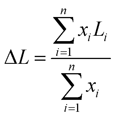
High-resolution transmission electron microscopy (HRTEM) characterization was performed on a JEM-2100 transmission electron microscope. Before characterization, tiny samples were dispersed in absolute ethanol by ultrasound, and a small number of liquid droplets were put on the copper mesh to be tested after volatilization. We acquired 25 representative pictures, including 400 slabs and 150 independent layered areas obtained from different regions of each catalyst. The average stacking number (ΔN) and average slab length (ΔL) were respectively calculated using the following equations14
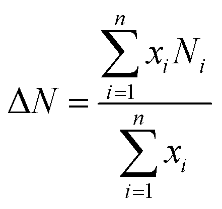
where i is the total number of MoS2 slabs. Ni and Li represent the stacking layer number and length of MoS2, respectively, and xi is the number of MoS2 slabs with Ni layers of length Li.
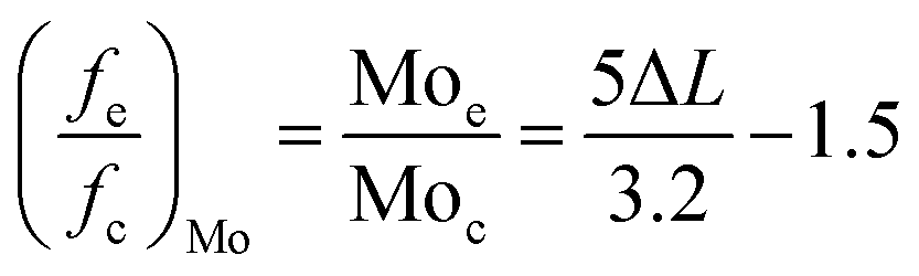
The Mo edge/corner ratio of the MoS2 slab ((fe/fc)Mo) was gained by the following equation:15
N2 adsorption–desorption (BET) isotherms were obtained on a QUADRASORB evo-2 automatic microporous physical adsorption instrument. The principle is that the surface of the sample is physically adsorbed with nitrogen at a low temperature to calculate the specific surface area and pore size distribution. The specific surface area of the sample was calculated by the BET (Brunauer–Emmett–Teller) formula. The pore size distribution was modeled by BJH (Barrett–Joyner–Halenda) analysis. The samples were vacuum degassed at 250 °C for 3 h before testing, and subsequently transferred to the analysis station for adsorption–desorption at −196 °C.
Raman spectra were obtained on a confocal inVia micro Raman spectrometer produced by Renishaw, UK. Monochrome light was scattered on the sample and the structural information of the samples was gained after calculating the wavelength of the scattered light. Generally speaking, the wavelength was mainly located in the range of molecular vibration, rotation and electronic level transition in the molecular system.
HDS of 4,6-DMDBT on the prepared MoS2
A mixture of 4,6-DMDBT and decalin (0.4 wt% S) was used as the simulated diesel oil to test the catalytic activity of MoS2; the test was performed in a microform high-pressure autoclave (200 mL). First, 70 mL of simulated diesel oil and 0.6 g catalyst were poured into the autoclave. The reactor was installed according to the operation and the gas tightness of the device was good before reaction, then hydrogen was injected three times into the autoclave to replace the air in the autoclave until it was discharged. The reaction conditions were as follows: H2, 3 MPa, 300 °C, 500 rpm, 5 h. After the reaction was finished, the power was turned off, and the gas discharged from the reactor was fed into the saturated NaOH solution when the temperature dropped to room temperature.Analysis of the total sulfur content of the solution after the HDS reaction was tested on a WK-2D microcoulomb comprehensive instrument, Jiangfen, from Jiangsu. The hydrocarbon composition was determined using a Pano A90 gas chromatograph equipped with an HP-5 (30 m × 0.32 mm × 0.25 μm) and FID detector for quantitative analysis; the qualitative analysis was carried out using a Trace 1310-ISQ LT GC-MS equipped with an HP-5.
The desulfurization ratio was calculated by the following equations:
The ratio of the product content of the HYD pathway to that of the DDS pathway was expressed by calculating the product selectivity S. The formula is as follows:
Results and discussion
XRD results
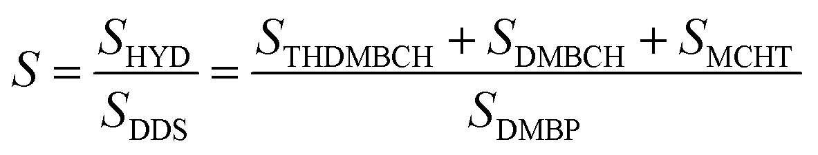
The preparation of the precursors was the first step in the preparation of MoS2. To determine the composition of the precursors, XRD characterization was conducted as shown in Fig. 1. Upon comparison with the standard card PDF 25-1978#, it was concluded that the precursor was MoO2 (DDTC)2, the complex of ammonium paramolybdate and DDTC. The formation mechanism of the precursor is as follows:| 20H+ + Mo7O246− + 14DDTC− → MoO2(DDTC)2 + 10H2O |
 | ||
| Fig. 1 The XRD spectra of the precursor. | ||
In the hydrothermal reaction, MoO2 (DDTC)2 decomposed into MoO42−, then the O2− was replaced by S2− and MoS2 was obtained.16
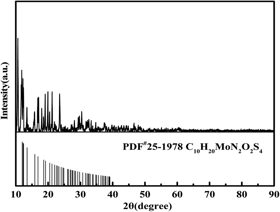
The XRD patterns of the three types of MoS2-X, with MoO2 (DDTC)2 as the precursor, are shown in Fig. 2. The peaks of the three types of MoS2 are similar, all exhibiting weak crystals of MoS2 synthesized according to different surfactant-assisted hydrothermal methods. The MoS2 peaks with 2θ at 34° and 57° were detected but not obvious in the three MoS2, and were attributed to the (100) and (110) planes of 2H-MoS2 (JCPDS card no.75–1539), respectively, which indicated that the three MoS2-X had the same arrangement of atoms in basal planes of 2H-MoS2.17 Moreover, the (002) peaks represented the accumulation of the S–Mo–S layers along the c-axis; since only weak van der Waals forces connect the MoS2 layers, it is very easy to insert heteroatoms between the layers.17,18 A weak peak at 9° was observed instead of the (002) peak at 14° for MoS2-CTAB, MoS2-SDS and MoS2-SDBS as compared to the pristine 2H-MoS2. This indicated that the (002) peaks moved forward, which was attributed to the increase in the interlayer spacing caused by the addition of surfactants,19,20 demonstrating that there were few stacking layers of MoS2. On the whole, the effects of the three surfactants on the crystalline form and intensities of MoS2-X in the hydrothermal reaction were slight, and all the MoS2 exhibited poor crystallinity, consistent with the previous results of the synthesis of MoS2 using the hydrothermal method.21
 | ||
| Fig. 2 XRD patterns of MoS2-CTAB, MoS2-SDBS, MoS2-SDS. | ||
FT-IR analysis
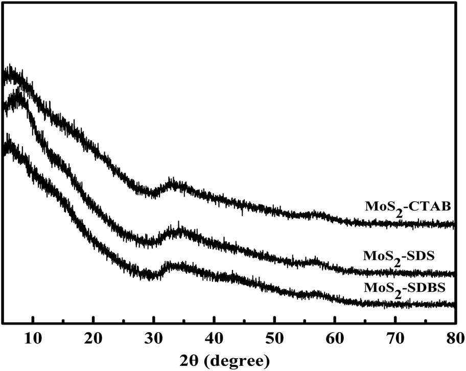
The FT-IR spectra of MoS2-CTAB (a), MoS2-SDS (b), MoS2-SDBS (c) are given in Fig. 3. The peaks at 3434 cm−1 and 1630 cm−1 for the three samples were assigned to the N–H stretching vibrations and C![[double bond, length as m-dash]](https://www.rsc.org/images/entities/char_e001.gif) S stretching vibrations of the amide bond from the precursor, respectively.22 The stronger intensity of MoS2-SDBS was because of the effect of the CC bond from the benzene ring in SDBS. The peaks at 2917 cm−1 and 2850 cm−1 were assigned to the stretching vibration modes of C–H from the surfactants (CTAB, SDS, SDBS).23 The C–H stretching vibration intensity was stronger in MoS2-CTAB than in the others, which was attributed to CTAB having the most C–H groups. The characteristic peaks of –SO2 from MoS2-SDBS appeared at about 1103 cm−1 and 1249 cm−1. In Fig. 3(c), the peak at 945 cm−1 was strengthened, which indicated that there was a strong coordination effect between MoS2 and SDBS rather than simple adsorption and modification.24
S stretching vibrations of the amide bond from the precursor, respectively.22 The stronger intensity of MoS2-SDBS was because of the effect of the CC bond from the benzene ring in SDBS. The peaks at 2917 cm−1 and 2850 cm−1 were assigned to the stretching vibration modes of C–H from the surfactants (CTAB, SDS, SDBS).23 The C–H stretching vibration intensity was stronger in MoS2-CTAB than in the others, which was attributed to CTAB having the most C–H groups. The characteristic peaks of –SO2 from MoS2-SDBS appeared at about 1103 cm−1 and 1249 cm−1. In Fig. 3(c), the peak at 945 cm−1 was strengthened, which indicated that there was a strong coordination effect between MoS2 and SDBS rather than simple adsorption and modification.24
 | ||
| Fig. 3 FT-IR spectra of the samples. (a) MoS2-CTAB; (b) MoS2-SDS; (c) MoS2-SDBS. | ||
SEM results
The SEM micrographs of the synthesized MoS2 with three surfactants are provided in Fig. 4. The introduction of three surfactants in the synthesis process gave rise to remarkable morphological changes in the MoS2. Some irregularly shaped particles with sizes ranging from 300 to 3000 nm were detected. MoS2-CTAB exhibited smooth, ball-like particles with sizes ranging from 400 to 2800 nm and larger; the particles were evenly dispersed and less agglomerated. This was attributed to the larger steric hindrance caused by the hydrophilic functional group ((CH3)3N−) of CTAB, which led to the larger size of the micelles formed by CTAB. In addition, the selective adsorption of CTA+ on the specific crystal surface of the nuclei of MoS2 limited the growth of the nuclei of MoS2 and hindered its reunion in the hydrothermal process, thus increasing its dispersion. The size of the MoS2 formed by CTAB as the template was fairly large;25 its average size was 1.2 um and the range of mean sizes was 700–900 nm. MoS2-SDBS exhibited rough, ball-like particles that were greatly aggregated; there were hardly any single ball-like structures. The average particle size was 800 nm in the range from 300 nm to 1.5 μm. MoS2-SDS exhibited a flower-like morphology with many stacked nanosheets, and the average thickness of the nanosheets was 15 nm, which indicated substantial aggregation.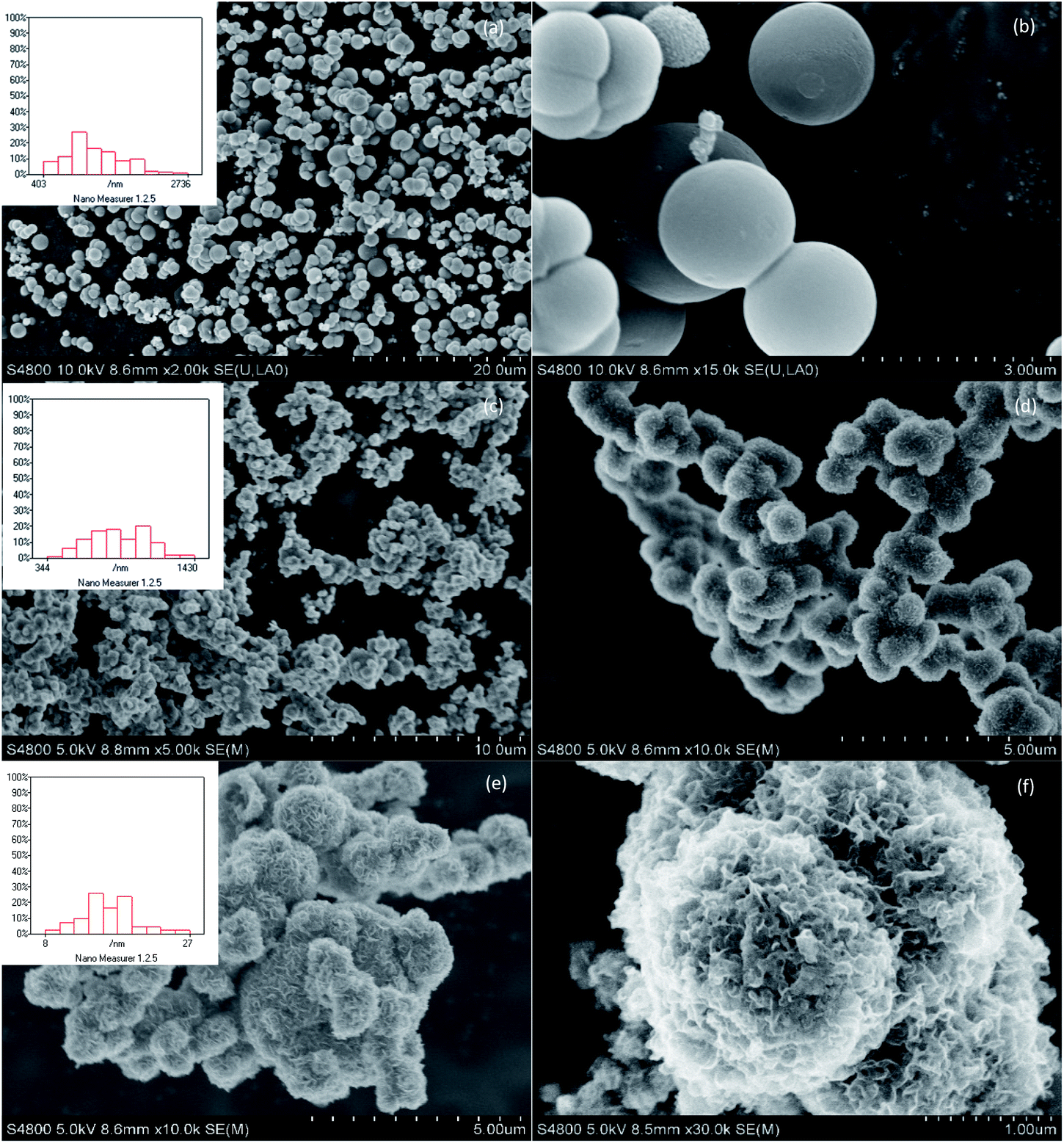 | ||
| Fig. 4 SEM micrographs of the MoS2-CTAB (a and b), MoS2-SDBS (c and d), MoS2-SDS (e and f). | ||
FETEM results
HRTEM studies were carried out in order to acquire more information regarding the distribution and structure of MoS2 as catalysts. The HRTEM images in Fig. 5 further show the specific outlines of the morphology of MoS2 prepared by heating at 220 °C for 24 h and adding CTAB, SDS and SDBS, respectively. It was found that the fringes of the three samples were arranged in a relatively disorderly manner, which may have been caused by cracks on the crystal plane. Those disorders led to the disorder of the interlayer arrangement, which resulted in the poor crystallinity of MoS2, entirely consistent with the XRD results. Typical MoS2 fringes with layer stacking spacing of 0.63 nm were visible on all the samples, in accordance with the characteristic crystalline MoS2 basal plane (002).26,27 The dislocations and distortions on the surface between different fringes indicated that the structure of MoS2 was defective and the existence of defects means the exposure of more active sites of MoS2.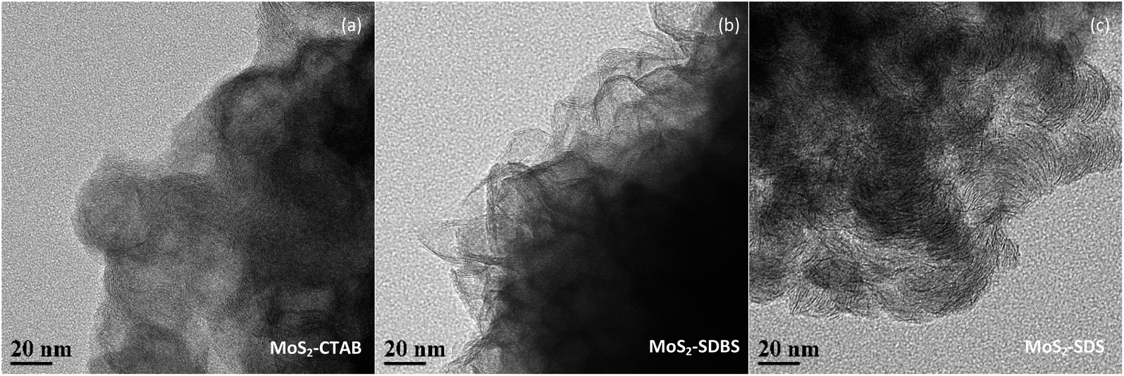 | ||
| Fig. 5 FETEM images of the MoS2-CTAB (a), MoS2-SDBS (b), MoS2-SDS (c). | ||
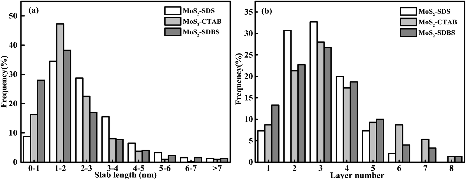
The distribution of the slab length and the layer numbers of the MoS2-X are presented in Fig. 6. The values of the average slab length, layer number and (fe/fc)Mo are shown in Table 1. By changing the type of surfactant, the synthesized MoS2 showed differences in slab length and layer number. The number of layers in MoS2-X was between 1 and 8, and the slab length was mostly within 7 nm. For all the MoS2 samples, the slab lengths were mostly between 1 and 2 nm and the number of layers was mostly 3. MoS2-SDS, MoS2-CTAB, and MoS2-SDBS accounted for 34.5%, 47.25%, and 38.25% of the total, respectively. With this as the demarcation point, the slab length first increased and then decreased. The percentage of MoS2 slabs with less than 5 layers exceeded 87.5% and the percentage of MoS2 slabs shorter than 4.0 nm exceeded 75%. As listed in Table 1, the average slab lengths of MoS2-SDS, MoS2-CTAB, and MoS2-SDBS were 2.35, 1.94, and 1.89 nm, the average numbers of layers were 2.95, 3.31, 3.62 nm, the dispersions were 3.16, 3.22, 3.26, and the values of (fe/fc)Mo were 2.45, 1.53, 1.45, respectively. There were three layers for MoS2-CTAB, and MoS2-SDBS, and MoS2-SDS had greater than three layers. The results, combined with the analysis results from Raman spectroscopy, are in good agreement with the FETEM results, suggesting that the distribution of MoS2 slabs was finely adjusted by adding different surfactants.
 | ||
| Fig. 6 Distributions of the slab length (a) and the layer number (b) of MoS2-CTAB, MoS2-SDBS, MoS2-SDS. | ||
| Catalysts | ΔN | ΔL | D | fe/fc |
|---|---|---|---|---|
| MoS2-CTAB | 3.31 | 1.94 | 3.22 | 1.53 |
| MoS2-SDS | 2.95 | 2.35 | 3.16 | 2.45 |
| MoS2-SDBS | 3.62 | 1.89 | 3.26 | 1.45 |
BET results
The specific surface area of MoS2 affects its catalytic performance to some extent. It was found that the specific surface areas of all the MoS2 synthesized by adding different surfactants were in the order of MoS2-SDBS > MoS2-SDS > MoS2-CTAB. From Table 2, the pore size followed the sequence of MoS2-CTAB > MoS2-SDBS > MoS2-SDS, and pore volume was of the order MoS2-SDBS > MoS2-CTAB > MoS2-SDS. MoS2-SDBS had the largest specific surface area and pore volume of 59.47 m2 g−1 and 11 cm3 g−1, respectively. The N2 adsorption–desorption and pore size distribution of MoS2 with different morphologies are illustrated in Fig. 7. The adsorption and desorption isotherms were classified as all delayed rings of type H3, which are associated with slit-shaped pores formed by the accumulation of plate-like particles and the existence of mesoporous structures, but there was no saturated adsorption platform. At 3–5 nm, this is consistent with the results of SEM characterization.| Samples | MoS2-CTAB | MoS2-SDS | MoS2-SDBS |
|---|---|---|---|
| Specific surface area (m2 g−1) | 28 | 33 | 59 |
| Pore volume (cm3 g−1) | 0.13 | 0.11 | 0.17 |
| Pore diameter (nm) | 3.82 | 3.82 | 3.82 |
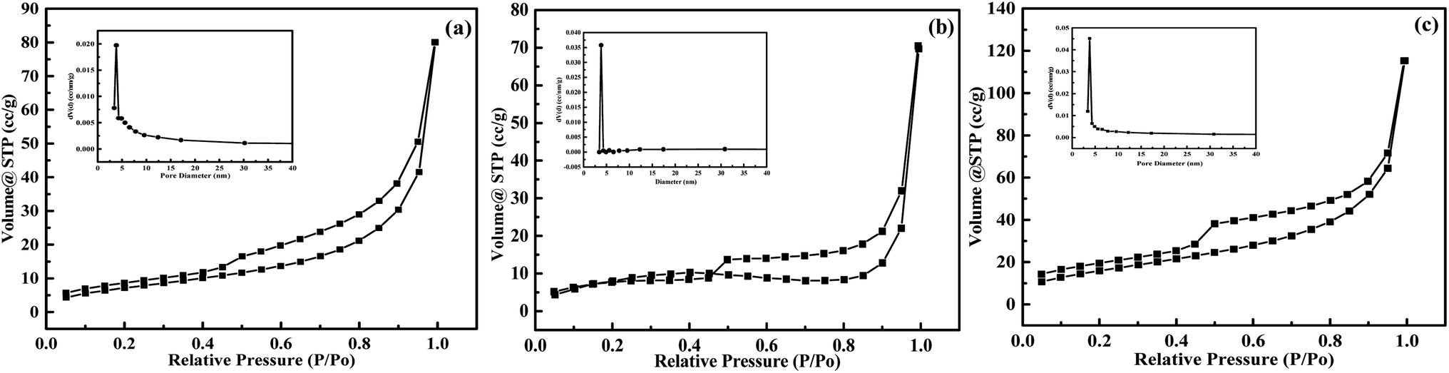 | ||
| Fig. 7 Adsorption–desorption isotherms and pore volume distribution curves of MoS2-CTAB (a), MoS2-SDBS (b), MoS2-SDS (c). | ||
Raman results
Raman spectroscopy is an effective method for characterizing the interface quality of 2H-MoS2. As layered materials with incomplete crystalline structures, the interface quality was affected by strain, defects and dislocation. The Raman spectra of the MoS2 series are displayed in Fig. 8. All the MoS2 samples exhibited typical bands in the E12g (378–382 cm−1) and A1g (404–408 cm−1) ranges; both the A1g peak and the E12g peak had blue-shifts, and the bands were attributed to the interlayer displacement of Mo and S atoms and outside vibrations of the Mo–S bond along the c-axis. Comparing the three morphologies of MoS2, the interaction intensity between the adjacent layers of MoS2-CTAB was the weakest. The low-angle displacement of the vibration peak position of E12g was caused by interlayer dislocations or intra-layer defects of Mo and S atoms in crystalline MoS2-CTAB and MoS2-SDBS, which could lead to greater exposure of edge active sites28,29. The distance between A1g and E12g (d = ν(A1g) − ν(E12g)) increased with the increasing layer number of MoS2.30 MoS2-CTAB displayed two peaks at 376 cm −1 (E12g) and 403 cm−1 (A1g), and d = 27 cm. MoS2-SDS displayed two peaks at 381 cm−1 (E12g) and 406 cm−1 (A1g) (d = 25 cm). MoS2-SDBS displayed two peaks at 378.5 cm−1 (E12g) and 403 cm−1 (A1g) (d = 24.5 cm). Raman spectroscopy demonstrated that the average layers of MoS2-SDS and MoS2-SDBS were three layers, in agreement with the HRTEM results.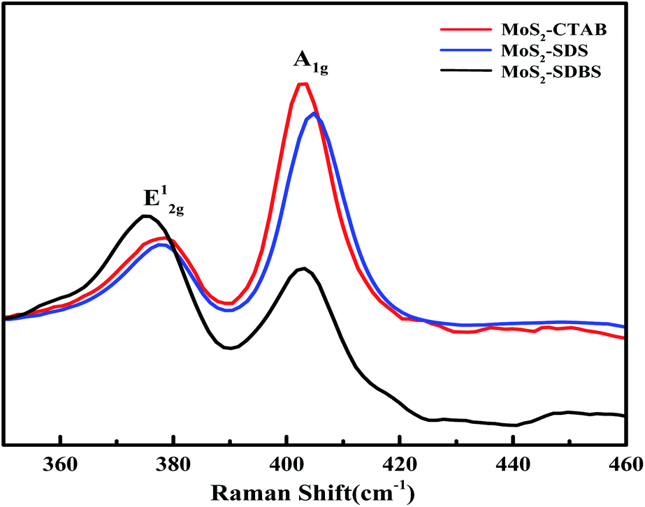 | ||
| Fig. 8 Raman spectra of MoS2-CTAB, MoS2-SDS, MoS2-SDBS. | ||
The formation mechanism of MoS2
According to the above characterization and results, MoO2(DDTC)2 was acidic (pH < 4) in aqueous solution and existed in the form of MoO42− and DDTC−; the O2− in MoO42− was easily replaced by S2− because of the weak Mo–O bond in MoO42−. MoO42− aggregated to form polymolybdate, and hydroxylamine hydrochloride was used as the reducing agent to reduce Mo(VI) to Mo(IV). During the hydrothermal reaction, DDTC− reacted with polymolybdate to form polytetrathiomolybdate, and the nucleus of MoS2 was finally formed by oxidation and reduction. The addition of surfactants resulted in different morphologies and structures of MoS2, and the surfactants also acted as templates in the hydrothermal processes. The insertion of surfactant into the layered structure of MoS2 led to the formation of nanosheets. These nanosheets aggregated on SDS/SDBS-formed micelles and grew into flower-like morphologies. When CTAB/SDS/SDBS was added to the reaction, the reaction mechanism was as given in Fig. 9(a) and (b). From Fig. 9(a), with CTAB as the cationic surfactant, MoO42− was adsorbed on it as a template to produce a smooth spherical morphology. When SDS and SDBS were added to the reaction system as anionic surfactants, the formation mechanism of MoS2 was similar. Specifically, the nanosheets were easier to grow along the (002) plane because this plane is the thermodynamically stable plane of MoS2 nanosheets. Fig. 9(b) shows the mechanism with SDS/SDBS as surfactants. During the reaction, SDBS and SDS were dissolved in water to form micelles; then, MoO42− was adsorbed onto the surface of the micelles. A large number of nanosheets were formed at the same time, and then those nanosheets were exfoliated and assembled into spheres under the action of the surfactants. In addition, the head-to-base ratio of SDBS is larger and more easily agglomerated to form micelles, as compared to SDS, which may explain why the morphology of MoS2-SDS is flower-like and MoS2-SDBS is rough-ball-like.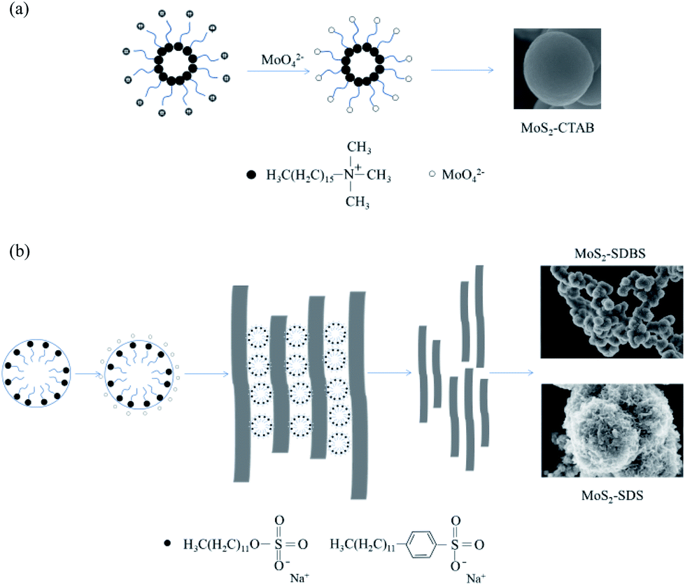 | ||
| Fig. 9 Schematic diagram of formation mechanism of MoS2-CTAB (a), MoS2-SDBS and MoS2-SDS (b). | ||
Catalytic activity
The hydrodesulfurization of 4,6-DMDBT can be divided into the hydrodesulfurization path (HYD) and the direct desulfurization path (DDS). HDS products of 4,6-DMDBT mostly contain THDMDBT, MCHT, DMBCH and DMBP. THDMDBT, MCHT and DMBCH are HYD products and DMBP are DDS products. The hydrogenation intermediate THDMDBT in the HYD pathway breaks the C–S bond to form MCHT, which is further hydrogenated to form DMBCH. In the DDS pathway, the C–S bond directly broke and generated the direct desulfurization product DMBP. The schematic diagram is shown in Fig. 10. The catalytic performances of MoS2-X in the HDS of simulated diesel oil (0.4 wt% S content of 4,6-DMDBT/decalin) are set out in Table 3. MoS2-SDBS exhibited the best HDS performance, with highest desulphurization, HYD ratio and selectivity, combined with FETEM analysis, the results showed that MoS2-SDBS had more active catalytic sites, which included edge sites and corner sites and this can be attributed to its shortest average slab length, average layer number and the smallest value of (fe/fc)Mo. The BET results showed that MoS2-SDBS had the largest specific surface area among the three MoS2. A comprehensive comparison of the results of HRTEM and BET analyses showed that they were accordant. The order of the ΔL and (fe/fc)Mo values of MoS2 with three morphologies from large to small is MoS2-SDS > MoS2-CTAB > MoS2-SDBS, while the order of ΔN and dispersion are the opposite, MoS2-SDBS > MoS2-CTAB > MoS2-SDS. Many studies have shown that HDS catalysts with shorter slab length, higher stacking and greater dispersion have better catalytic performances because more active sites are exposed.31–34 Therefore, the catalytic activities of the three MoS2 can be inferred as follows: MoS2-SDBS > MoS2-CTAB > MoS2-SDS. The shortest slab length, the smallest value ratio of Mo edge sites to corner sites and the greatest dispersion of MoS2-SDBS determine that it has the most active sites and the larger corner position as compared to the other two catalysts, which ultimately led to the best HDS performance. The desulfurization rate of MoS2-X was arranged in the order of MoS2-SDBS > MoS2-SDS > MoS2-CTAB. According to BET and HRTEM results, the specific surface area and pore volume of MoS2-SDBS were larger than those of MoS2-CTAB and MoS2-SDS. This may be the point of the higher desulfurization rate of MoS2-SDBS. From the analysis results, the desulfurization rate of 4,6-DMDBT was influenced greatly by the average slab length, followed by the average number of layers and finally the value of (fe/fc)Mo. In addition, the HYD ratio and selectivity of MoS2-X were in the order of MoS2-SDBS > MoS2-CTAB > MoS2-SDS. The three MoS2 as catalysts preferred to react along the HYD path. The (fe/fc)Mo value of MoS2 was negatively correlated with the degree of hydrogenation. It was reported that the corner sites on the MoS2 are favorable for HYD reactions and the edge sites on the MoS2 promote HDS reactions because the corner sites are more favorable for the adsorption and dissociation of molecular hydrogen into ionic hydrogen.34 The values of (fe/fc)Mo were calculated in combination with HRTEM: fe/fc (MoS2-SDBS) > (fe/fc)Mo (MoS2-CTAB) > (fe/fc)Mo (MoS2-SDS), which exhibited the same trends as the HYD ratio and selectivity of MoS2-X. These results can be reviewed as the reason the HYD ratio and selectivity of MoS2-CTAB are higher as compared to MoS2-SDS. In conclusion, the desulfurization rate of MoS2-X is positively correlated with the average number of layers and the HYD ratio and selectivity are positively correlated with the average slab length, and the ratio of the Mo edge/corner.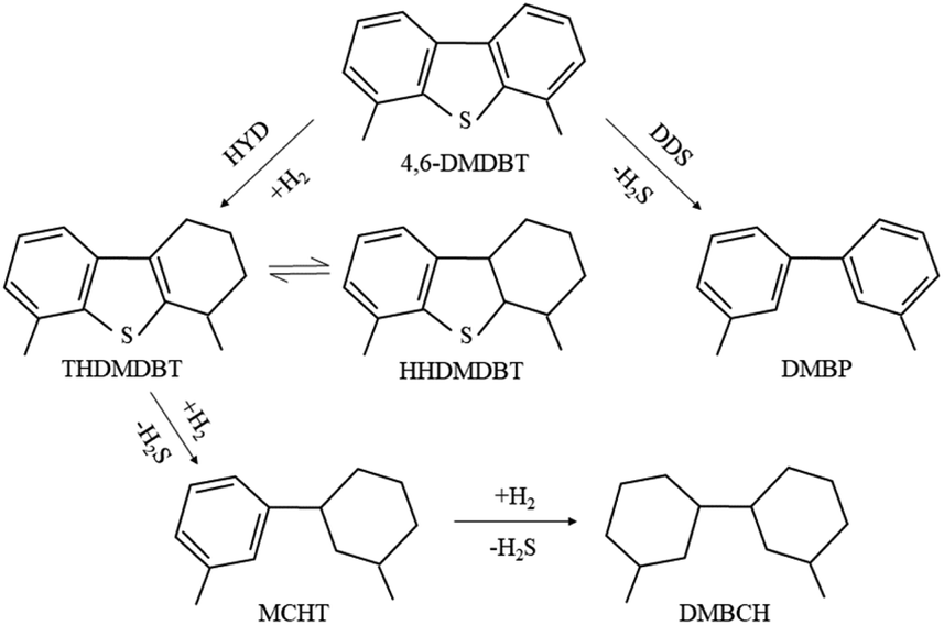 | ||
| Fig. 10 Schematic diagram of the hydrodesulfurization path of 4,6-DMDBT. | ||
| Catalysts | Desulphurization (%) | HYD ratio (%) | Path selectivity |
|---|---|---|---|
| MoS2-CTAB | 58.5 | 37.1 | 1.6 |
| MoS2-SDS | 44.6 | 26.3 | 1.1 |
| MoS2-SDBS | 95.9 | 90.1 | 15.5 |
Reuse rate of MoS2-SDBS
MoS2-SDBS has the best catalytic activity of three catalysts; its morphology, structure and reuse in the HDS process have been studied. Fig. 11 compares the XRD spectra of MoS2-SDBS before and after the HDS reaction. MoS2-SDBS, after HDS reaction, exhibited higher crystallinity than it did before the HDS reaction, which may be due to the high temperature during the reaction. Fig. 12 shows SEM micrographs of MoS2-SDBS after the HDS reaction; the morphology changed from rough, spherical particles before the reaction to granular particles that just stuck together after the reaction. MoS2-SDBS after the HDS reaction was used as a catalyst for HDS to explore the reuse rate; the result showed that the desulphurization of the catalyst was 78.7% as compared with MoS2-SDBS without HDS. The desulfurization rate was reduced by 17.9%, which showed that its reuse rate had decreased.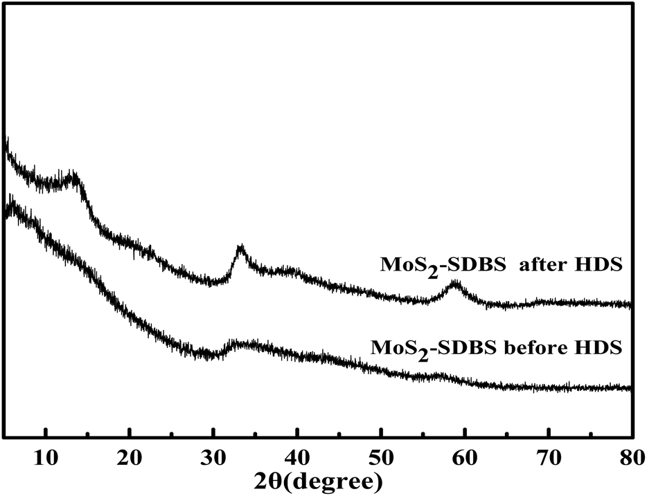 | ||
| Fig. 11 XRD patterns of MoS2-SDBS before and after HDS. | ||
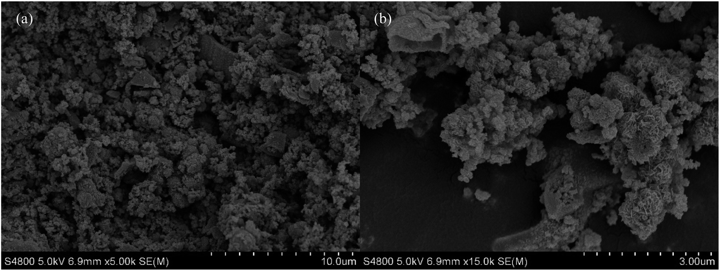 | ||
| Fig. 12 SEM micrographs of MoS2-SDBS (a and b) after HDS. | ||
Conclusions
Three types of MoS2 were synthesized for use as catalysts by the combination of the precursor method and the hydrothermal method and were used in HDS to assess their catalytic activity. The results are as follows. The smooth-surfaced and ball-like, rough-surfaced and ball-like, and flower-like morphologies of MoS2 were prepared with the assistance of different surfactants (CTAB/SDBS/SDS). The TEM images showed that in general, the average slab length and the ratio of edge/corner of the MoS2 increased remarkably in the following order: MoS2-SDBS > MoS2-CTAB > MoS2-SDS. The average number of layers was in the order MoS2-SDBS > MoS2-SDS > MoS2-CTAB. When MoS2 was used as the catalyst in hydrodesulfurization, the desulfurization rate of the MoS2 increased in the order MoS2-SDBS > MoS2-SDS > MoS2-CTAB, which exhibited a positive correlation with the average number of layers and dispersion of MoS2. The HYD ratio and selectivity of the MoS2 increased in the order MoS2-SDBS > MoS2-CTAB > MoS2-SDS, which exhibited a negative correlation with the average slab length and the ratio of Mo edge/corner sites of MoS2. The results showed that MoS2-SDBS exhibited the highest HDS performance among the three catalysts because it had the shortest average slab length, highest Mo ratio of edge to corner, and highest dispersion and specific surface area. The HDS performance of the reused MoS2-SDBS was lower than that of the original MoS2-SDBS.Conflicts of interest
There are no conflicts to declare.Acknowledgements
The work was supported by National Natural Science Foundation of China projects (Grant No. 21603077, 51603077) and the industry-University-Research Collaborative Innovation Project of Xiamen (Grant No. 3502z20183024).Notes and references
- S. Oda and K. Cui, J. Jpn. Pet. Inst., 2004, 47, 145–163 CrossRef.
- A. Stanislaus, A. Marafi and M. S. Rana, Catal. Today, 2010, 153, 1–68 CrossRef CAS.
- Y. Wang, C. Yin, X. Zhao and C. Liu, Catal. Commun., 2017, 88, 13–17 CrossRef CAS.
- X. Li, Y. Chai, B. Liu, H. Liu, J. Li, R. Zhao and C. Liu, Ind. Eng. Chem. Res., 2014, 53, 9665–9673 CrossRef CAS.
- Y. Wang, C. Yin, X. Zhao and C. Liu, Catal. Commun., 2017, 88, 13–17 CrossRef CAS.
- W. Zhou, Q. Wei, Y. Zhou, M. Liu, S. Ding and Q. Yang, Appl. Catal., B, 2018, 238, 212–224 CrossRef CAS.
- M. Li, D. Wang, J. Li, Z. Pan, H. Ma, Y. Jiang and Z. Tian, RSC Adv., 2016, 6, 71534–71542 RSC.
- H. Miao, X. Hu, Q. Sun, Y. Hao, H. Wu, D. Zhang, J. Bai, E. Liu, J. Fan and X. Hou, Mater. Lett., 2016, 166, 121–124 CrossRef CAS.
- Y. Li, H. Li, S. Zhou, H. Yang, F. Xie and W. Li, Res. Chem. Intermed., 2018, 44, 4353–4364 CrossRef CAS.
- Y. Li, X. Zhang, W. Zhang, M. Chang, C. Lin, K. Chang, Y. Yu, J. Wang, C. Chang, L. Li and T. Lin, Adv. Mater., 2012, 24, 2320–2325 CrossRef PubMed.
- K. Hu, Y. Wang, X. Hu and H. Wo, J. Mater. Sci. Nanotechnol., 2013, 23, 242–246 CrossRef.
- T. Wang, J. Li and G. Zhao, Powder Technol., 2014, 253, 347–351 CrossRef CAS.
- J. Theerthagiri, R. A. Senthil, B. Senthilkumar, A. Reddy Polu, J. Madhavan and M. Ashokkumar, J. Solid State Chem., 2017, 252, 43–71 CrossRef CAS.
- A. M. van der Kraan, V. H. J. de Beer, J. A. R. van Veen and R. A. van Santen, J. Catal., 2001, 199, 224–235 CrossRef.
- H. Li, W. Zhang, Y. Wang, M. Shui, S. Sun, J. Bao and C. Gao, J. Energy Chem., 2019, 30, 57–62 CrossRef.
- W. Hu, G. Han, F. Dai, Y. Liu, X. Shang, B. Dong, Y. Chai, Y. Liu and C. Liu, Int. J. Hydrogen Energy, 2016, 41, 294–299 CrossRef CAS.
- J. Xie, Z. Hao, L. Shuang, R. Wang, S. Xu, Z. Min, J. Zhou, W. L. Xiong and X. Yi, Adv. Mater., 2013, 25, 5807–5813 CrossRef CAS PubMed.
- J. Xie, J. Zhang, S. Li, F. Grote, X. Zhang, H. Zhang, R. Wang, Y. Lei, B. Pan and Y. Xie, J. Am. Chem. Soc., 2013, 136, 17881–17888 CrossRef PubMed.
- F. Wang, M. Zheng, B. Zhang, C. Zhu, Q. Li, L. Ma and W. Shen, Sci. Rep., 2016, 6, 31092 CrossRef CAS PubMed.
- Y. Tian, J. Zhao, W. Fu, Y. Liu, Y. Zhu and Z. Wang, Mater. Lett., 2005, 59, 3452–3455 CrossRef CAS.
- X. Xie, L. Gao and J. Sun, Colloids Surf., A, 2007, 308, 54–59 CrossRef CAS.
- X. Tian, M. Fang, C. Chen, S. Yu and X. Wang, Carbon, 2008, 46, 1741–1750 CrossRef.
- Z. Wu, D. Wang and A. Sun, Mater. Lett., 2009, 63, 2591–2593 CrossRef CAS.
- Y. Zhang, W. Zeng and Y. Li, Appl. Surf. Sci., 2018, 455, 276–282 CrossRef CAS.
- E. Payen, R. Hubaut, S. Kasztelan, O. Poulet and J. Grimblot, J. Catal., 1994, 147, 123–132 CrossRef CAS.
- T. Fujikawa, H. Kimura, K. Kiriyama and K. Hagiwara, Catal. Today, 2006, 111, 188–193 CrossRef CAS.
- C. Lee, H. Yan, L. E. Brus, T. F. Heinz, J. Hone and S. Ryu, ACS Nano, 2010, 4, 2695–2700 CrossRef CAS PubMed.
- H. Li, Q. Zhang, C. C. R. Yap, B. K. Tay, T. H. T. Edwin, A. Olivier and D. Baillargeat, Adv. Funct. Mater., 2012, 22, 1385–1390 CrossRef CAS.
- J. Xu, Y. Guo, T. Huang and Y. Fan, Appl. Catal., B, 2019, 244, 385–395 CrossRef CAS.
- Y. Gao, W. Han and X. Long, Appl. Catal., B, 2018, 224, 330–340 CrossRef CAS.
- W. Han, P. Yuan, Y. Fan, G. Shi, H. Liu, D. Bai and X. Bao, J. Mater. Chem., 2012, 22, 25340–25353 RSC.
- S. V. Budukva, O. V. Klimov and A. S. Noskov, Catal. Ind., 2015, 7, 214–220 CrossRef.
- L. Woolfolk, C. Geantet, L. Massin, D. Laurenti and J. D. Reyes, Appl. Catal., B, 2017, 201, 31–338 CrossRef.
- M. Li, H. Li, F. Jiang, Y. Chu and H. Nie, Catal. Today, 2010, 149, 35–39 CrossRef CAS.
| This journal is © The Royal Society of Chemistry 2020 |