Role of double interfaces in inspiring energy storage devices in CC@Ni(OH)Cl@NiO flexible electrodes†
Sixian
Fu
a,
Liping
Li
a,
Lingshen
Meng
a,
Mengyue
Gao
a,
Shuaikai
Xu
b,
Xiyang
Wang
a,
Yuelan
Zhang
a and
Guangshe
Li
 *a
*a
aState Key Laboratory of Inorganic Synthesis and Preparative Chemistry, College of Chemistry, Jilin University, Changchun 130012, P. R. China. E-mail: guangshe@jlu.edu.cn
bKey Laboratory of Physics and Technology for Advanced Batteries, Ministry of Education, Jilin University, Changchun 130012, P. R. China
First published on 9th November 2019
Abstract
Interfacial engineering is highly promising in the research field of flexible energy storage devices. Massive efforts have confirmed the beneficial effects of controlled interfaces in enhancing energy storage. Despite the extensive studies on constructing multilevel interfaces in the fabrication of flexible electrodes, a deep understanding of the role of interfaces from the electrochemical perspective is lacking, particularly the operational feasibility in extreme conditions. Herein, we designed a carbon cloth (CC) based double-interface CC@Ni(OH)Cl@NiO by a solvothermal, chemical bath, and subsequent annealing method. We obtained both remarkable areal capacitance (8290 mF cm−2 at 30 mA cm−2) and excellent cycling stability (73.9% capacitance retention after 1000 cycles), approximately double than those for the single-interface CC@Ni(OH)Cl. Correspondingly, ultrahigh current tolerance was endowed with a stable charge–discharge capacitance of 3580 mF cm−2 at 120 mA cm−2. A flexible quasi-solid-state asymmetric supercapacitor device, CC@Ni(OH)Cl@NiO//graphene, was assembled, which achieved favorable capacitive ability and splendid flexibility as well as mechanical stability. Through the synchrotron radiation technique, we demonstrated that synergistic double interfaces afford the benefits of stable Ni–O covalency during the electrochemical cycles, and meanwhile bring about more structural distortion and active electronic behavior on the surface state, which simultaneously stimulated capacitive ability and stability. Importantly, our study reveals a positive role of double interfaces from the electrochemical perspective of flexible electrodes for widespread energy storage in the future.
Introduction
Interfacial engineering is one of the most important frontiers and hotspots in many functional applications, concerning heterogeneous catalysis,1 photovoltaic conversion,2 biomedical nanotechnology,3 and energy storage.4 Among these advanced research fields, the interface technology continues to blossom in flexible energy storage devices because of urgent demands for portable and wearable electronics.5–9 For example, the assembled flexible Ni2+//Fe3+ colloidal capacitor was reported via an optimized surface/interface of a carbon cloth supported colloids to achieve an ultrahigh energy density.10 By artificially introducing an interface based on a polyacrylamide/gelatin gel, the free-standing NiFe2O4–CNT composite anode obtained a high-performance application for flexible lithium-ion batteries.11 A solution-processed C70 interlayer between TiO2 and (HC(NH2)2PbI3)x(CH3NH3PbCl3)1−x for interface engineering prominently enhanced the efficiency of flexible perovskite solar cells.12 Although these extensive efforts have confirmed the effective roles of controlled interfaces in enhancing the flexible energy storage, the main focus is still on the construction of multilevel interfaces, hence a thorough understanding on the role of interfaces from the electrochemical perspective is lacking. Correspondingly, the operational feasibility of the flexible electrodes in harsh conditions is also limited.13,14 For supercapacitors, the practical applications at ultrahigh current densities are always restricted by severe capacitance decay even to electrode damage.15–17 Therefore, it is highly challenging and meaningful to clarify the internal role of multilevel interfaces for efficient and secure energy storage in flexible devices.Enlightened by this, we selected nickel hydroxychloride, Ni(OH)Cl, as a model to introduce multilevel interfaces, which was first found to be a promising energy storage material in our previous study.18 The regulation of interlayer spacing endowed layered Ni(OH)Cl with an optimized capacitive performance, but still, severe capacitance attenuation and bad stability at high current densities were observed. According to the micromorphology, Ni(OH)Cl microspheres, assembled by the close-packed flower-like nanoflakes, were adverse to charge transfer and electrolyte ion migration. Combining the successful interface engineering examples,19–23 we proposed a strategy to construct the primary interface by dispersedly anchoring Ni(OH)Cl nanoflakes on a conductive carbon cloth, where a strong interfacial interaction would come into being between the material and substrate. Furthermore, the flexible electrode was also attainable. In reference to the crystal structure, the layered Ni(OH)Cl that was built up from neutral layers of [Ni(OH)3/3Cl3/3] octahedrons went through Cl− deintercalation/OH− intercalation from the lattice at electrode/electrolyte interface during the electrochemical cycles.18 The secondary interface could be built on the surface of Ni(OH)Cl by coating a protective layer that prevents direct contact with the electrolyte. We put the spotlight on NiO partly because of its intrinsic chemical/thermal stability and superior redox reactivity,24,25 but more importantly, because both NiO and Ni(OH)Cl have Ni–O bonds in the octahedron of the crystal structure. The strong interfacial bonding may be in favor of stabilizing the electrochemical charge–discharge process.26 Such double interfaces design is expected to enhance the electrochemical performance, simultaneously contributing to a better understanding on the role of interfaces by a sequence of characterizations.
In this study, we designed a double-interface CC@Ni(OH)Cl@NiO flexible electrode via a two-step interfacial engineering. First, the flower-like Ni(OH)Cl nanoflake arrays were anchored on the carbon cloth (CC@Ni(OH)Cl) via a solvothermal method. Second, a protective NiO coating layer was built on the surface of Ni(OH)Cl (CC@Ni(OH)Cl@NiO) by chemical bath and subsequent annealing method. The double-interface CC@Ni(OH)Cl@NiO electrode delivered both ultrahigh areal capacitance and excellent cycling stability at high current densities as compared to the single-interface CC@Ni(OH)Cl. More importantly, the ultrahigh current tolerance was found for it, and superior flexible device application was also achieved. Through X-ray absorption near-edge spectroscopy, we proposed a mechanism on how synergistic double interfaces afford the benefits of stable Ni–O covalency during the electrochemical cycles and bring about the modulation of the surface electronic state that integrates the electrochemical stability and capacitive ability. Importantly, the present interfacial engineering reveals a positive role of double interfaces on the electrochemical properties of flexible electrodes, which offers an avenue for universal energy storage.
Experimental
Construction of single-interface CC@Ni(OH)Cl
All the reagents were of analytical grade and used without any further treatment. The carbon cloth was ultrasonically washed for 30 min using a mixture of water, ethanol, and acetone, and then dried in a vacuum oven at 75 °C for 12 h. In a typical process, 8 mmol of NiCl2·6H2O was added into 60 mL of ethanol under magnetic stirring to form a homogenous solution. Subsequently, the solution was transferred into a Teflon-lined autoclave (100 mL), and then, a piece of carbon cloth (3 × 4 cm2) was immersed in it. After that, the autoclave was sealed and heated at 180 °C for 12 h. Until the system naturally cooled down to room temperature, the obtained Ni(OH)Cl on the carbon cloth was washed with deionized water and ethanol several times and dried in an oven at 60 °C for 4 h. The as-prepared single-interface electrode was denoted as CC@Ni(OH)Cl. The average loading mass of Ni(OH)Cl on the carbon cloth was determined to be 3.4 mg cm−2.Construction of double-interface CC@Ni(OH)Cl@NiO
NiO was coated on Ni(OH)Cl by chemical bath precipitation and subsequent annealing treatment. First, 25 mmol of NiCl2·6H2O and 5 mmol of K2S2O8 were dissolved in 45 mL of deionized water. Subsequently, 5 mL of NH3·H2O was fast dropped into the solution, and then CC@Ni(OH)Cl was immersed and kept in it for 10 min. Then, it was washed with deionized water and ethanol and was finally annealed in N2 atmosphere under 350 °C for 2 h. The as-obtained double-interface electrode was denoted as CC@Ni(OH)Cl@NiO. The average loading mass of Ni(OH)Cl@NiO on the carbon cloth was estimated to be 3.7 mg cm−2.Synthesis of template-free Ni(OH)Cl microspheres
The template-free Ni(OH)Cl microspheres were synthesized according to our previous study.18 10 mmol of NiCl2·6H2O was dissolved into 60 mL of ethanol. After that, the solution was transferred into a Teflon-lined autoclave (100 mL), which was sealed and heated at 180 °C for 12 h. The acquired powders were washed using deionized water and ethanol several times and eventually dried at 70 °C for 12 h.Construction of other single-interface CC@Ni(OH)NO3 and CC@Ni(OH)CH3COO
Based on the screening of various experimental conditions, the best construction process is as follows: 10 mmol of Ni(NO3)2·6H2O and Ni(CH3COO)2·4H2O were dividedly dissolved into 60 mL of ethanol under magnetic stirring. Then, the solutions were transferred into two Teflon-lined autoclaves (100 mL) with the pretreated carbon cloth (3 × 4 cm2) being immersed. After that, two autoclaves were sealed and heated for 12 h at 200 °C and 180 °C, respectively. The as-constructed single-interface electrodes were marked as CC@Ni(OH)NO3 and CC@Ni(OH)CH3COO.Construction of Ni(OH)Cl pasted on carbon cloth electrode
Ni(OH)Cl pasted on carbon cloth was prepared as a contrast electrode by following steps: 90 wt% of the template-free Ni(OH)Cl powders (3.4 mg) and 10 wt% of the polytetrafluoroethylene (PTFE) were mixed in a mortar, and then, the obtained mixture was uniformly pasted on a piece of carbon cloth (1 × 1 cm2). The as-prepared electrode was dried at 60 °C for 4 h and was denoted as Ni(OH)Cl pasted on CC.Fabrication of flexible quasi-solid-state asymmetric supercapacitor device
CC@Ni(OH)Cl@NiO electrode (2 × 2 cm2) was directly used as the positive electrode. The negative electrode was prepared by homogeneously mixing 80 wt% of the graphene, 10 wt% of the acetylene black, and 10 wt% of the polytetrafluoroethylene (PTFE). After that, the mixture was pasted onto a piece of carbon cloth (2 × 2 cm2), which was designated as graphene pasted on CC. PVA/KOH gel electrolyte was made as follows: 6 g of PVA was dissolved in 30 mL of deionized water, and the mixture was heated at 90 °C under continuous stirring until a transparent PVA solution was obtained. After the solution cooled down to room temperature, 3 g of KOH was dissolved in 20 mL of H2O, which was dropped into the PVA solution and stirred to a clear PVA/KOH gel electrolyte. The two electrodes were covered with PVA/KOH gel electrolyte and pressed together face to face by placing between them a filter membrane as the separator, constructing a sandwich structure. Subsequently, they were encased with the copper foil and PVC film. The as-fabricated flexible quasi-solid-state asymmetric supercapacitor device was referred to as CC@Ni(OH)Cl@NiO//graphene.Characterizations
The morphology and microstructure of the electrodes were observed via the field-emission scanning electron microscopy (SEM) (JSM-6700F) and high-resolution transmission electron microscopy (HRTEM) (TecnaiG2 S-Twin F20). The energy dispersive spectroscopy (EDS) (Oxford X-Max80) was employed to acquire the elemental distribution and mapping images. The phase structure of the electrodes was characterized via X-ray diffraction (Rigaku miniflex600) with Cu Kα radiation (λ = 0.1518 nm). X-ray photoelectron spectroscopy (XPS) (ESCA-LAB 250) with a monochromatic Al Kα (hν = 1486.6 eV) radiation source was performed to determine the chemical compositions and oxidation states for the electrodes. The charging shifts were calibrated by a primary C 1s value at 284.6 eV. The nitrogen adsorption–desorption isotherm was determined using a Brunauer–Emmett–Teller (BET) equation by a surface area analyzer ASAP 2020 (Micromeritics). The X-ray absorption near-edge structure (XANES) of O K-edge and Ni L-edge were collected at the BL12B-a beamline of National Synchrotron Radiation Laboratory (NSRL).Electrochemical measurements
The electrochemical workstation (CHI 760E, Chenhua Instruments, China) was used to measure all electrochemical performances. The electrochemical measurements of all individual electrodes were performed via a three-electrode cell with 6 M KOH aqueous solution as the electrolyte. A Pt foil was used as the counter electrode, and a Hg/HgO electrode was used as the reference electrode. The electrochemical measurements of the flexible quasi-solid-state asymmetric supercapacitor device were executed by a two-electrode system, in which the positive electrode was CC@Ni(OH)Cl@NiO, and the negative electrode was graphene pasted on CC.Results and discussion
Architecture of double-interface CC@Ni(OH)Cl@NiO electrode
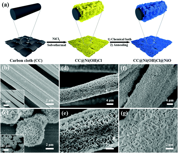
The two-step interfacial engineering of double-interface CC@Ni(OH)Cl@NiO is schematically shown in Fig. 1a. First, flower-like Ni(OH)Cl nanoflakes were vertically anchored on the flexible carbon cloth via a facile solvothermal method after a series of modulation based on our previous study.18 In this step, the preprocessed carbon cloth, easily absorbing Ni2+ ions on the surface, went through a hydroxychlorinated nucleation in ethanol, generating nickel hydrochloride Ni(OH)Cl anchored on it, which was single-interface CC@Ni(OH)Cl. Furthermore, CC@Ni(OH)Cl was used as a template, and a NiO coating layer was precipitated on it by a chemical bath deposition method. From the complex chemical bath solution containing Ni2+ and S2O82−, it was easy to form 4Ni(OH)2·NiOOH precursor on the surface of Ni(OH)Cl after adding NH3·H2O. The subsequent annealing treatment transformed 4Ni(OH)2·NiOOH to NiO.24 As a result, the double-interface CC@Ni(OH)Cl@NiO flexible electrode was successfully constructed.The product of each step was observed by SEM (Fig. 1b–g). The bare carbon cloth after ultrasonic pretreatment had a smooth surface (Fig. 1b), and the inset shows that the carbon cloth was woven by carbon fibers. Fig. 1c shows the morphology of Ni(OH)Cl microspheres composed of close-packed flower-like nanoflakes, which were synthesized by a template-free method. In a pure solvothermal system, without any template, Ni(OH)Cl went through a self-assembly nucleation process, eventually forming hierarchical microspheres. When the bare carbon cloth was used as the template, Ni(OH)Cl nanoflake arrays were grown dispersedly on the surface of carbon fibers (Fig. 1d and e). Since the nanoflakes are interconnected microstructure, the obtained CC@Ni(OH)Cl had highly porous architecture. For fabricating this perfectly ranged microstructure, we explored many experimental conditions by screening the samples, and the corresponding SEM images are displayed in Fig. S1 (ESI†). Subsequently, NiO was coated onto Ni(OH)Cl nanoflake arrays, which in turn formed a double-interface structure. As shown in Fig. 1f and g, CC@Ni(OH)Cl@NiO also consists of numerous nanoflakes with random orientation. Compared to CC@Ni(OH)Cl, the interconnected nanoflakes became more close-knit because NiO coating layer caused it to thicken. From SEM observation, we preliminarily judged that the double-interface CC@Ni(OH)Cl@NiO flexible electrode was successfully built. In addition, in the first solvothermal step, we explored other Ni2+ metallic salts in ethanol solution such as Ni(NO3)2 and Ni(CH3COO)2 to construct other single-interface CC@Ni(OH)NO3 and CC@Ni(OH)CH3COO. Morphologies obtained under various experimental conditions are correspondingly shown in Fig. S2 and S3 (ESI†). The well-constructed CC@Ni(OH)NO3 exhibited little thick pieces arranged vertically on the carbon fibers (Fig. S2c, ESI†), while well-constructed CC@Ni(OH)CH3COO showed big thin sheets on the carbon fibers with many particles embedded (Fig. S3e and f, ESI†).
To further detect the elemental distribution of double-interface CC@Ni(OH)Cl@NiO, EDS mapping was measured with single-interface CC@Ni(OH)Cl for comparison. For CC@Ni(OH)Cl in Fig. 2a, it was observed that the signals corresponding to Ni and Cl element got enriched at the edge of the carbon fiber, while C signal augmented at the center. This increase in signals can be attributed to the overlapping of the flower-like Ni(OH)Cl nanoflakes at the two sides of cylindrical fiber from the vertical viewpoint of Fig. 2a, while the bare surface at the center of carbon fiber was exposed by this porous microstructure built by interconnected Ni(OH)Cl nanoflakes. As for CC@Ni(OH)Cl@NiO in Fig. 2b, Ni and Cl elements were found to get homogeneously distributed throughout the fiber, while the signal corresponding to the C element was not enriched at the center, demonstrating that uniform NiO coating layer made Ni(OH)Cl nanoflakes more thicker and denser, due to the fact that porous structure was blocked to a certain extent. The EDS mapping result further confirmed that double-interface CC@Ni(OH)Cl@NiO was well-constructed.
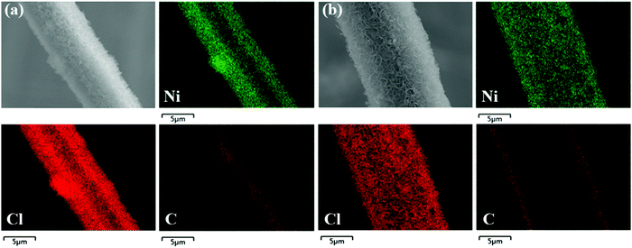 | ||
| Fig. 2 SEM image and corresponding EDS elemental mapping images for Ni, Cl, and C of (a) CC@Ni(OH)Cl and (b) CC@Ni(OH)Cl@NiO. | ||
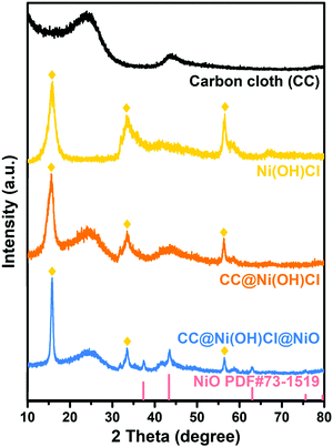
XRD patterns were recorded to confirm the crystal and phase structure of double-interface CC@Ni(OH)Cl@NiO. As depicted in Fig. 3, no sharp diffraction peaks were found for carbon cloth, except two broad peaks at around 24° and 43°, corresponding to (002) and (100) planes in the amorphous carbon.27 The template-free Ni(OH)Cl had similar diffraction peak positions to those of our previous study, with a typical layered crystal structure.18 CC@Ni(OH)Cl simultaneously possessed narrow diffraction peaks of Ni(OH)Cl and broad peaks of amorphous carbon cloth, illustrating a combination of layered Ni(OH)Cl and amorphous carbon cloth substrate. On the basis of CC@Ni(OH)Cl, NiO was coated by chemical bath precipitation, which was validated by the standard diffraction peaks of cubic phase NiO (JCPDS card no. 73-1519) in CC@Ni(OH)Cl@NiO. Further, X-ray crystallography analysis proved that the as-prepared CC@Ni(OH)Cl@NiO was made up of cubic NiO, layered Ni(OH)Cl, and amorphous carbon cloth.
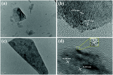
For further investigating the interfacial structure of double-interface CC@Ni(OH)Cl@NiO, Ni(OH)Cl and Ni(OH)Cl@NiO nanoflakes were stripped from carbon cloth by ultrasonic treatment to obtain their TEM and HRTEM images at different magnification. In Fig. 4a, Ni(OH)Cl showed thin slice morphology with a wrinkle. According to the HRTEM images of it in Fig. 4b, the chaotic lattice fringe with distances of 0.271 and 0.272 nm, were randomly distributed throughout the slice, which is the characteristic of Ni(OH)Cl assembled by numerous nanoparticles,18 similar to the reported multi-lattice compound.28 As shown in Fig. 4c, Ni(OH)Cl with a NiO coating layer distinctly became thick in size though it also exhibited a slice morphology. When we focused the edge of the slice in HRTEM (Fig. 4d), an obvious coating layer was observed with a regular lattice spacing of 0.208 nm, corresponding to the (200) plane of cubic NiO. The internal part clearly showed a chaotic lattice fringe with distances of 0.258 and 0.252 nm for Ni(OH)Cl. An obvious interfacial boundary between NiO and Ni(OH)Cl can be seen, demonstrating the formation of Ni(OH)Cl/NiO interface. TEM and HRTEM images provided a visual proof of the architecture of double-interface CC@Ni(OH)Cl@NiO, in agreement with the XRD result.
To confirm the variations of surface composition and valence state before and after the second chemical bath precipitation step, we compared the XPS spectra in Fig. 5. As shown in Fig. 5a, the survey spectra indicated the presence of C, Ni, O, and Cl elements in both CC@Ni(OH)Cl and CC@Ni(OH)Cl@NiO. Ni 2p spectrum of CC@Ni(OH)Cl (Fig. 5b) had two spin–orbit peaks with two satellite peaks (signed as “Sat.”). The two spin–orbit peaks were centered at 855.6 eV (Ni 2p3/2) and 873 eV (Ni 2p1/2) with an energy separation of 17.4 eV, which was assigned to Ni2+ chemical state in Ni(OH)Cl.18,29 Apparently, Ni 2p3/2 and Ni 2p1/2 spin–orbit peak positions of CC@Ni(OH)Cl@NiO shifted to lower binding energy, which was consistent with the chemical state of standard NiO.30 Moreover, similar to the O 1s spectra in Fig. 5c, CC@Ni(OH)Cl showed only one photoelectron peak at a binding energy of 530.2 eV, which was ascribed to the hydroxyl oxygen in Ni(OH)Cl.18,31 Differently, the O 1s spectrum of CC@Ni(OH)Cl@NiO was deconvoluted into two peaks, corresponding to two oxygen species. The peak at a binding energy of 529.5 eV was assigned to lattice oxygen bonding with nickel in NiO,30,32 and the peak at 531.7 eV corresponds to the trace hydroxyl oxygen and absorbed water on the surface.33,34 Cl 2p spectra of CC@Ni(OH)Cl and CC@Ni(OH)Cl@NiO showed a clear distinction in Fig. 5d. This was attributed to the construction of the interface between NiO and Ni(OH)Cl that affected the intrinsic charging state of Cl in the internal Ni(OH)Cl.35
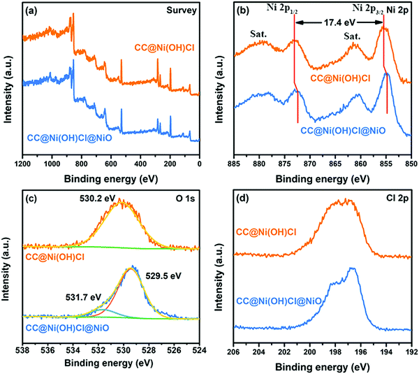 | ||
| Fig. 5 XPS spectra of CC@Ni(OH)Cl and CC@Ni(OH)Cl@NiO: (a) survey, (b) Ni 2p, (c) O 1s, and (d) Cl 2p. | ||
Specific surface area and porous structure of the electrodes have a significant influence on the electrochemical properties. From nitrogen adsorption/desorption isotherms, shown in Fig. 6a, one can observe that both CC@Ni(OH)Cl and CC@Ni(OH)Cl@NiO had obvious hysteresis loops, compared to bare carbon cloth, suggesting larger Brunauer–Emmett–Teller (BET) surface areas than the carbon cloth.36 Further, as shown in Fig. 6b, the pore-size distributions of CC@Ni(OH)Cl and CC@Ni(OH)Cl@NiO, determined by Barrett–Joyner–Halenda (BJH) method, showed a distribution varying from 2 to 65 nm (∼20 nm), demonstrating their mesoporous features, which was generated by the interconnected nanoflake arrays.37 In contrast, in the bare carbon cloth, we can hardly observe any porous features. The rational architecture of double-interface CC@Ni(OH)Cl@NiO based on the construction of CC/Ni(OH)Cl primary interface brings large surface area and abundant pore distributions, which will facilitate efficient charge transport and electrolyte ion access, as well as excellent capacitive performance.38
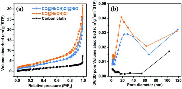 | ||
| Fig. 6 (a) Nitrogen adsorption/desorption isotherms and (b) pore-size distributions of carbon cloth, CC@Ni(OH)Cl, and CC@Ni(OH)Cl@NiO. | ||
Electrochemical performance of double-interface CC@Ni(OH)Cl@NiO electrode for flexible supercapacitor application
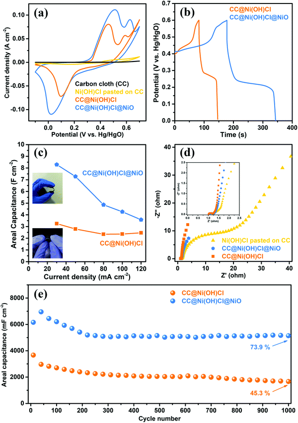
The electrochemical performance of the double-interface CC@Ni(OH)Cl@NiO electrode was evaluated by a three-electrode system, with Ni(OH)Cl pasted on CC and CC@Ni(OH)Cl electrodes being used for comparison. The cyclic voltammetry (CV) curves of the electrodes, at a scan rate of 5 mV s−1 in the potential range from −0.1 to 0.7 V versus Hg/HgO electrode were obtained and are shown in Fig. 7a. The carbon cloth almost contributed no capacitance in such an alkaline electrolyte. In terms of Ni(OH)Cl pasted on CC electrode, only a puny current signal was detected, implying weak interaction between Ni(OH)Cl active material and carbon cloth substrate. Compared with Ni(OH)Cl pasted on CC electrode, the CC@Ni(OH)Cl with an equal weight of Ni(OH)Cl active material delivered significantly higher capacitance, indicating strong interfacial interaction by successfully constructing CC/Ni(OH)Cl interface. CC@Ni(OH)Cl and CC@Ni(OH)Cl@NiO electrodes exhibited intense and typical redox peaks, corresponding to ideal pseudocapacitive behaviors that involve reversible faradaic redox reactions of Ni2+/Ni3+.39,40 In particular, the electrochemical redox reaction of CC@Ni(OH)Cl electrode can be described as follows:| Ni(OH)Cl + OH− ⇌ NiOOH + HCl + e− | (1) |
| NiO + OH− ⇌ NiOOH + e− | (2) |
Both CC@Ni(OH)Cl and CC@Ni(OH)Cl@NiO electrodes showed only one asymmetric reduction peak, which resulted from the partial overlap of the corresponding two reduction peaks. Remarkably, the enclosed CV curve area and the redox peak current of the double-interface CC@Ni(OH)Cl@NiO electrode were the largest among these electrodes, suggesting the greatest capacitive ability,41 which may result from the well construction of another Ni(OH)Cl/NiO interface. Moreover, the CV curves of CC@Ni(OH)Cl@NiO, CC@Ni(OH)Cl, and Ni(OH)Cl pasted on CC electrodes with scan rates from 5 to 40 mV s−1 in various potential windows are presented in Fig. S4–S6 (ESI†).
A comparison of galvanostatic charge–discharge (GCD) curves (Fig. 7b) for CC@Ni(OH)Cl@NiO and CC@Ni(OH)Cl was measured at a high current density of 30 mA cm-2. As expected, the double-interface CC@Ni(OH)Cl@NiO electrode exhibited a longer charge–discharge plateau than that of single-interface CC@Ni(OH)Cl, indicating a larger specific capacitance,42 and further proving the key role of Ni(OH)Cl/NiO interface, in agreement with the CV results shown above. Moreover, two typical charge plateaus and one distinct discharge plateau for the asymmetric GCD curves coincided well with the redox peaks in CV curves, suggesting the pseudocapacitive characteristics of the faradaic reaction.24,43 Interestingly, the voltage of the discharge plateau for CC@Ni(OH)Cl@NiO electrode had a slight decrease when compared with CC@Ni(OH)Cl electrode, which may be caused by the change in ion migration rate due to the formation of Ni(OH)Cl/NiO interface. For meeting a broad application, we conducted GCD measurements of the electrodes under high current densities of 30, 50, 80, 100, and 120 mA cm−2 (Fig. S7a and b, ESI†). The high current densities usually lead to severe capacitance decay even to electrode damage,18 which is due to abrupt incremental voltage drop and insufficient redox reactions.44 GCD curves of CC@Ni(OH)Cl@NiO and CC@Ni(OH)Cl electrodes retained their initial asymmetric shapes, which represented stable rate charge–discharge behavior,45 illustrating the valid design of CC/Ni(OH)Cl primary interface. In contrast, Ni(OH)Cl pasted on CC electrode can be charged/discharged only at low current densities of 4–10 mA cm−2 (Fig. S7c, ESI†). These results illustrated that a strong interaction of CC/Ni(OH)Cl interface could greatly enhance the charge and mass transfer efficiency of the electrode.
Based on GCD curves, areal capacitance and specific capacitance under various current densities for CC@Ni(OH)Cl@NiO and CC@Ni(OH)Cl electrodes were calculated using eqn (3) and (4)
 | (3) |
 | (4) |
The electrochemical impedance spectroscopy (EIS) was further measured to investigate the electronic and ionic conductivities of these electrodes. As shown in Fig. 7d, the Nyquist plots consisted of a linear shape in the low-frequency region and a semicircle in the high-frequency region. The straight line in the low-frequency region represents the diffusive impendence of electrolyte ions to the electrode surface (Warburg resistance, Zw). The semicircle in the high-frequency region corresponds to the electron transfer kinetics of the redox reaction at the electrode/electrolyte interface (charge-transfer resistance, Rct).40,46 According to these plots, both double-interface CC@Ni(OH)Cl@NiO and single-interface CC@Ni(OH)Cl electrodes displayed evidently larger slopes and smaller semicircle diameters than the Ni(OH)Cl pasted on CC electrode, which corresponded to lower Zw and Rct values, implying faster ion diffusion rates and superior electron transport kinetics at or near the electrode/electrolyte interface.40,47 CC@Ni(OH)Cl@NiO electrode, having similar Rct value to that of CC@Ni(OH)Cl electrode, showed a relatively lower slope in low-frequency region, which is due to NiO coating layer that formed Ni(OH)Cl/NiO interface and brought a relatively close-packed microstructure that narrowed the porous channel for the migration of electrolyte ions to some extent.
Long-term cycling stability under high current densities is a crucial parameter for the practical application of supercapacitors.24 The electrochemical cycling performance of double-interface CC@Ni(OH)Cl@NiO electrode was investigated by GCD measurements, with CC@Ni(OH)Cl being used for comparison at a high current density of 30 mA cm−2 for 1000 cycles, as shown in Fig. 7e. The variation of the areal capacitance for CC@Ni(OH)Cl@NiO electrode experienced a trend of rising first and then falling in the first 200 cycles and after that remains stable, while that for CC@Ni(OH)Cl electrode continues to decline until the end. Remarkably, the CC@Ni(OH)Cl@NiO electrode finally retained 73.9% of the 40th discharge capacitance after 1000 cycles, much better than 45.3% capacitance retention of CC@Ni(OH)Cl electrode. Our previous studies reported that pure Ni(OH)Cl would go through a Cl− deintercalation/OH− intercalation process during the electrochemical cycles when it directly contacted with the strong alkali electrolyte, which led to severe capacitance degradation.18 In the double-interface CC@Ni(OH)Cl@NiO electrode, the rational design of the Ni(OH)Cl/NiO secondary interface is bound to play a vital role in dramatically improving the cycling stability.
The electrochemical properties of other single-interface CC@Ni(OH)NO3 and CC@Ni(OH)CH3COO electrodes were also evaluated, as shown in Fig. S8 (ESI†). The CV curves of both CC@Ni(OH)CH3COO (Fig. S8a, ESI†) and CC@Ni(OH)NO3 (Fig. S8b, ESI†) electrodes showed typical pseudocapacitive characterization. Comparative GCD curves (Fig. S8c, ESI†) revealed that CC@Ni(OH)NO3 and CC@Ni(OH)CH3COO electrodes also possessed energy storage abilities. However, CC@Ni(OH)Cl electrode with a higher capacitance was more suitable for introducing double interfaces, which can also be confirmed by better electron and ion migratory behavior reflected in the Nyquist plots (Fig. S8d, ESI†). From the point of other aspects, the solvothermal strategy for building the primary interface of these CC@Ni(OH)X (X = Cl−, NO3−, CH3COO−etc.) electrodes could be widely expanded, and the resulting electrodes have the potential for fabricating other high-performance devices.
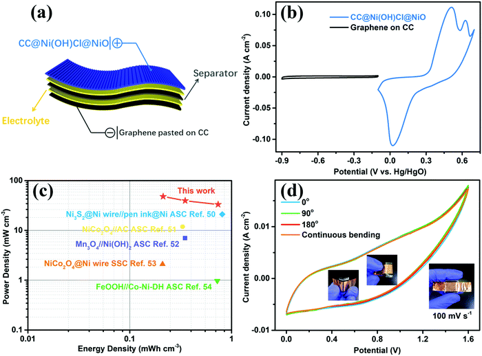
To estimate the practical application of the double-interface CC@Ni(OH)Cl@NiO electrode, a flexible quasi-solid-state asymmetric supercapacitor device was fabricated. As illustrated in Fig. 8a, the rechargeable device was composed of CC@Ni(OH)Cl@NiO as a positive electrode, graphene on CC as a negative electrode, PVA/KOH gel as an electrolyte, and a filter membrane as the separator, thereby denoting the device as CC@Ni(OH)Cl@NiO//graphene. The CV and GCD curves of graphene on CC electrode are shown in Fig. S9 (ESI†), which suggested a typical electrical double-layer capacitive characteristic. The CV curves of CC@Ni(OH)Cl@NiO and graphene on CC electrodes at 5 mV s−1 are shown in Fig. 8b with a potential range of −0.1 to 0.7 V and −0.9 to −0.1 V, respectively. For CC@Ni(OH)Cl@NiO//graphene device, the CV curves can maintain a similar shape under small operating windows (Fig. S10a, ESI†). Accordingly, the potential window of CC@Ni(OH)Cl@NiO//graphene device was selected as 0–1.6 V. The CV curves of the CC@Ni(OH)Cl@NiO//graphene device at different scan rates are displayed in Fig. S10b (ESI†), whose approximately rectangular shapes means an outstanding capacitive ability.42 The volumetric capacitance under various scan rates for the as-fabricated CC@Ni(OH)Cl@NiO//graphene device were calculated based on eqn (5)48
 | (5) |
 | (6) |
 | (7) |
Mechanism about the role of double interfaces on electrochemical performance of CC@Ni(OH)Cl@NiO electrode
In order to clarify the detailed role of double interfaces on such prominent electrochemical performance, O K-edge and Ni L-edge XANES spectra of double-interface CC@Ni(OH)Cl@NiO electrode before and after electrochemical cycles, were measured along with the single-interface CC@Ni(OH)Cl electrode for comparison (Fig. 9). In the case of O K-edge (the left pattern), CC@Ni(OH)Cl electrode showed two peaks, labeled by arrows, at 528.2 and 530.2 eV (Fig. 9a), corresponding to two split eg spin orbits with a spin–orbit splitting of 2 eV, which originated from the asymmetric octahedral distortion in Ni(OH)Cl.18 In contrast, NiO generally shows a single peak in that region because of its NiO6 regular octahedron.55,56 When Ni(OH)Cl/NiO secondary interface was built by NiO coating layer (Fig. 9b), the relative intensity of the peak labeled by red arrow became weak, and this region infinitely approximated to a single-peak situation. In addition, both peaks simultaneously shifted to lower energy, i.e., 527.8 and 529.8 eV, which was attributed to the reduced covalency of Ni–O bond resulting from strong interfacial bonding between Ni(OH)Cl and NiO.57 After CC@Ni(OH)Cl@NiO electrode went through long-term electrochemical cycles (Fig. 9c), the main peak at 527.8 eV maintained its original position, demonstrating a stable Ni–O bond covalency by strong interfacial bonding, which is considered as the crucial reason for its superior cycling stability and ultrahigh current tolerance. Furthermore, the peak labeled by red arrow distinctly became intense and shifted to 529.2 eV with a reduced spin–orbit splitting at 1.4 eV, suggesting more structural distortion and active electronic behavior on the surface state at the electrode/electrolyte interfaces induced by strong interfacial interaction between carbon cloth and Ni(OH)Cl,58–60 as both are favorable for pseudocapacitive redox reactivity of CC@Ni(OH)Cl@NiO electrode. As for the Ni L-edge, shown in the right pattern, CC@Ni(OH)Cl electrode showed the main peak at 844.4 eV, with a shoulder peak labeled by the yellow arrow. When NiO layer gets coated, the main peak shifted to higher energy, i.e., 844.6 eV, while the position remained constant even if it went through long-term electrochemical cycles, which is in agreement with the O K-edge result. The mechanism proposed after analyzing the XANES spectra was consistent with our electrochemical results that the synergistic double interfaces exhibits a positive role in such outstanding electrochemical performance of CC@Ni(OH)Cl@NiO flexible electrode.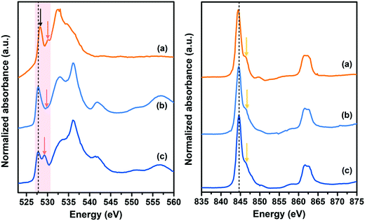 | ||
| Fig. 9 O K-edge (left) and Ni L-edge (right) XANES spectra of (a) CC@Ni(OH)Cl, (b) CC@Ni(OH)Cl@NiO, and (c) CC@Ni(OH)Cl@NiO after electrochemical cycles. | ||
Conclusions
We designed a novel double-interface CC@Ni(OH)Cl@NiO flexible electrode by a two-step interfacial engineering. A positive role of CC/Ni(OH)Cl and Ni(OH)Cl/NiO interfaces on electrochemical properties of flexible CC@Ni(OH)Cl@NiO electrode was revealed. A flexible quasi-solid-state asymmetric supercapacitor device, CC@Ni(OH)Cl@NiO//graphene, was assembled, which achieved favorable capacitive ability and splendid flexibility as well as mechanical stability. X-ray absorption near-edge spectroscopy confirmed that the synergistic double interfaces integrate the electrochemical stability and capacitive ability together. In CC@Ni(OH)Cl@NiO electrode, the strong interfacial bonding between Ni(OH)Cl and NiO stabilized the covalency of Ni–O bond during the long-term electrochemical cycles, which is considered as the crucial reason for superior cycling stability and ultrahigh current tolerance. The strong interfacial interaction between carbon cloth and Ni(OH)Cl induced more structural distortion and active electronic behavior on the surface state at the electrode/electrolyte interfaces, as both are favorable for pseudocapacitive redox reactivity. The present interfacial engineering provides insight into the role of double interfaces on flexible energy storage and ideas for the design of high-performance multiple-interfaces electrodes.Conflicts of interest
There are no conflicts to declare.Acknowledgements
This work is financially supported by National Natural Science Foundation of China (NSFC) (Grants 21571176, 21871106, 21671077 and 21771075) and Interdisciplinary Research Grant for PhDs of Jilin University (10183201816). We acknowledge the National Synchrotron Radiation Laboratory (NSRL) beamline BL12B-a for providing beam time.Notes and references
- Q. Shao, P. Wang and X. Huang, Adv. Funct. Mater., 2019, 29, 1806419 CrossRef
.
- A. Rajagopal, K. Yao and A. K. Jen, Adv. Mater., 2018, 30, 1800455 CrossRef PubMed
.
- D. K. Ye, X. L. Zuo and C. H. Fan, Annu. Rev. Anal. Chem., 2018, 11, 171–195 CrossRef CAS
.
- V. R. Stamenkovic, D. Strmcnik, P. P. Lopes and N. M. Markovic, Nat. Mater., 2017, 16, 57–69 CrossRef CAS
.
- H. Li, Z. Tang, Z. Liu and C. Zhi, Joule, 2019, 3, 613–619 CrossRef
.
- X. Chen, J. A. Rogers, S. P. Lacour, W. Hu and D. H. Kim, Chem. Soc. Rev., 2019, 48, 1431–1433 RSC
.
- X. Min, B. Sun, S. Chen, M. Fang, X. Wu, Y. G. Liu, A. Abdelkader, Z. Huang, T. Liu, K. Xi and R. V. Kumar, Energy Storage Mater., 2019, 16, 597–606 CrossRef
.
- N. W. Li, Y. Shi, Y. X. Yin, X. X. Zeng, J. Y. Li, C. J. Li, L. J. Wan, R. Wen and Y. G. Guo, Angew. Chem., Int. Ed., 2018, 57, 1505–1509 CrossRef CAS
.
- R. Peng, W. Song, T. Yan, B. Fanady, Y. Li, Q. Zhan and Z. Ge, J. Mater. Chem. A, 2019, 7, 11460–11467 RSC
.
- X. Liang, K. Chen and D. Xue, Adv. Energy Mater., 2018, 8, 1703329 CrossRef
.
- L. Liu, M. Zhu, S. Huang, X. Lu, L. Zhang, Y. Li, S. Wang, L. Liu, Q. Weng and O. G. Schmidt, J. Mater. Chem. A, 2019, 7, 14097–14107 RSC
.
- Y. Q. Zhou, B. S. Wu, G. H. Lin, Y. Li, D. C. Chen, P. Zhang, M. Y. Yu, B. B. Zhang and D. Q. Yun, ACS Appl. Mater. Interfaces, 2017, 9, 33810–33818 CrossRef CAS
.
- M. Cheng, Y. Meng, Q. Meng, L. Mao, M. Zhang, K. Amin, A. Ahmad, S. Wu and Z. Wei, Mater. Chem. Front., 2018, 2, 986–992 RSC
.
- A. Platek, J. Piwek, K. Fic, T. Schubert, P. Gentile, G. Bidan and E. Frackowiak, J. Mater. Chem. A, 2017, 5, 22708–22716 RSC
.
- L. Dong, X. Ma, Y. Li, L. Zhao, W. Liu, J. Cheng, C. Xu, B. Li, Q.-H. Yang and F. Kang, Energy Storage Mater., 2018, 13, 96–102 CrossRef
.
- Q. Dou, S. Lei, D. W. Wang, Q. Zhang, D. Xiao, H. Guo, A. Wang, H. Yang, Y. Li, S. Shi and X. Yan, Energy Environ. Sci., 2018, 11, 3212–3219 RSC
.
- N. Batisse and E. Raymundo-Piñero, J. Power Sources, 2017, 348, 168–174 CrossRef CAS
.
- S. Fu, L. Li, Y. Zhang, S. Chen, S. Fang, Y. Jing and G. Li, ACS Appl. Energy Mater., 2018, 1, 1522–1533 CrossRef CAS
.
- D. Wang, R. Yu, S. Feng, W. Zheng, G. Pang and H. Zhao, Chem. J. Chin. Univ., 1998, 19, 165–168 CAS
.
- Z. Xue, X. Li, Q. Liu, M. Cai, K. Liu, M. Liu, Z. Ke, X. Liu and G. Li, Adv. Mater., 2019, 31, 1900430 CrossRef CAS
.
- Y. Yan, W. Li, J. Cai, M. Chen, Y. Mao, X. Chen, R. S. Gurney, D. Liu, F. Huang and T. Wang, Mater. Chem. Front., 2018, 2, 1859–1865 RSC
.
- Y. Bai, H. Huang, C. Wang, R. Long and Y. Xiong, Mater. Chem. Front., 2017, 1, 1951–1964 RSC
.
- C. Gu, C. Jia and X. Guo, Mater. Chem. Front., 2017, 1, 2125–2131 RSC
.
- Y. Ouyang, R. Huang, X. Xia, H. Ye, X. Jiao, L. Wang, W. Lei and Q. Hao, Chem. Eng. J., 2019, 355, 416–427 CrossRef CAS
.
- Y. Shu, Y. Yan, J. Chen, Q. Xu, H. Pang and X. Hu, ACS Appl. Mater. Interfaces, 2017, 9, 22342–22349 CrossRef
.
- Y. P. Zhu, C. Guo, Y. Zheng and S. Z. Qiao, Acc. Chem. Res., 2017, 50, 915–923 CrossRef CAS
.
- P. Lu, Y. Sun, H. Xiang, X. Liang and Y. Yu, Adv. Energy Mater., 2018, 8, 1702434 CrossRef
.
- Y. Xu, H. Jiang, S. Fu, J. Li, N. Nakayama, D. Wang, J. Xu, T. Song and S. Feng, Chem. J. Chin. Univ., 2009, 30, 456–459 CAS
.
- S. Liu, S. C. Lee, U. Patil, I. Shackery, S. Kang, K. Zhang, J. H. Park, K. Y. Chung and S. Chan Jun, J. Mater. Chem. A, 2017, 5, 1043–1049 RSC
.
- M. A. Peck and M. A. Langell, Chem. Mater., 2012, 24, 4483–4490 CrossRef CAS
.
- Y. Fu, J. Song, Y. Zhu and C. Cao, J. Power Sources, 2014, 262, 344–348 CrossRef CAS
.
- D. Alders, F. Voogt, T. Hibma and G. Sawatzky, Phys. Rev. B: Condens. Matter Mater. Phys., 1996, 54, 7716–7719 CrossRef CAS
.
- H. Li, L. Li, S. Fang, J. Wang, S. Chen, X. Huang, Z. Leng and G. Li, Environ. Sci.: Nano, 2018, 5, 2368–2381 RSC
.
- S. Liu, S. C. Lee, U. M. Patil, C. Ray, K. V. Sankar, K. Zhang, A. Kundu, S. Kang, J. H. Park and S. C. Jun, J. Mater. Chem. A, 2017, 5, 4543–4549 RSC
.
- A. Shchukarev, J. Rosenqvist and S. Sjöberg, J. Electron Spectrosc. Relat. Phenom., 2004, 137–140, 171–176 CrossRef CAS
.
- Y. Cao, X. Wang, Z. Gu, Q. Fan, W. Gibbons, V. Gadhamshetty, N. Ai and G. Zeng, J. Power Sources, 2018, 384, 360–366 CrossRef CAS
.
- H. Wang, L. Zhai, Y. Li and T. Shi, Mater. Res. Bull., 2008, 43, 1607–1614 CrossRef CAS
.
- Z. Xiao, Y. Bao, Z. Li, X. Huai, M. Wang, P. Liu and L. Wang, ACS Appl. Energy Mater., 2019, 2, 1086–1092 CrossRef CAS
.
- A. K. Tomar, G. Singh and R. K. Sharma, ChemSusChem, 2018, 11, 4123–4130 CrossRef CAS
.
- Y. Li, Y. Xu, Y. Liu and H. Pang, Small, 2019, 15, 1902463 CrossRef PubMed
.
- S. Fu, L. Li, Y. Jing, Y. Zhang, X. Wang, S. Fang, J. Wang and G. Li, Cryst. Growth Des., 2018, 18, 6107–6116 CrossRef CAS
.
- D. Chen, S. Zhou, H. Quan, R. Zou, W. Gao, X. Luo and L. Guo, Chem. Eng. J., 2018, 341, 102–111 CrossRef CAS
.
- J. Zhao, Z. Li, X. Yuan, T. Shen, L. Lin, M. Zhang, A. Meng and Q. Li, Chem. Eng. J., 2019, 357, 21–32 CrossRef CAS
.
- V. Augustyn, P. Simon and B. Dunn, Energy Environ. Sci., 2014, 7, 1597–1614 RSC
.
- S. Xu, Y. Dall’Agnese, G. Wei, C. Zhang, Y. Gogotsi and W. Han, Nano Energy, 2018, 50, 479–488 CrossRef CAS
.
- H. Wang, W. Wang, H. Wang, X. Jin, H. Niu, H. Wang, H. Zhou and T. Lin, ACS Appl. Energy Mater., 2018, 1, 431–439 CrossRef CAS
.
- M. M. Vadiyar, X. Liu and Z. Ye, ChemSusChem, 2018, 11, 2410–2420 CrossRef CAS
.
- D. Du, R. Lan, J. Humphreys, H. Amari and S. Tao, Electrochim. Acta, 2018, 273, 170–180 CrossRef CAS
.
- J. Cao, J. Li, L. li, Y. Zhang, D. Cai, D. Chen and W. Han, ACS Sustainable Chem. Eng., 2019, 7, 10699–10707 CrossRef CAS
.
- J. Wen, S. Li, K. Zhou, Z. Song, B. Li, Z. Chen, T. Chen, Y. Guoand and G. Fang, J. Power Sources, 2016, 324, 325–333 CrossRef CAS
.
- C. Liu, W. Jiang, F. Hu, X. Wu and D. F. Xue, Inorg. Chem. Front., 2018, 5, 835–843 RSC
.
- J. Feng, S. Ye, X. Lu, Y. Tong and G. Li, ACS Appl. Mater. Interfaces, 2015, 7, 11444–11451 CrossRef CAS
.
- A. Ramadoss, K. N. Kang, H. J. Ahn, S. I. Kim, S. T. Ryu and J. H. Jang, J. Mater. Chem. A, 2016, 4, 4718–4727 RSC
.
- J. Chen, J. Xu, S. Zhou, N. Zhao and C. Wong, Nano Energy, 2016, 21, 145–153 CrossRef CAS
.
- I. Davoli, A. Marcelli, A. Bianconi, M. Tomellini and M. Fanfoni, Phys. Rev. B: Condens. Matter Mater. Phys., 1986, 33, 2979–2982 CrossRef CAS
.
- H. Kurata, E. Lefèvre, C. Colliex and R. Brydson, Phys. Rev. B: Condens. Matter Mater. Phys., 1993, 47, 13763–13768 CrossRef CAS
.
- S. Hwang, S. M. Kim, S.-M. Bak, K. Y. Chung and W. Chang, Chem. Mater., 2015, 27, 6044–6052 CrossRef CAS
.
- A. Grimaud, K. J. May, C. E. Carlton, Y. L. Lee, M. Risch, W. T. Hong, J. Zhou and Y. Shao-Horn, Nat. Commun., 2013, 4, 2439 CrossRef
.
- X. Wang, K. Huang, L. Yuan, S. Xi, W. Yan, Z. Geng, Y. Cong, Y. Sun, H. Tan, X. Wu, L. Li and S. Feng, J. Phys. Chem. Lett., 2018, 9, 4146–4154 CrossRef CAS PubMed
.
- X. Wang, K. Huang, L. Yuan, S. Li, W. Ma, Z. Liu and S. Feng, ACS Appl. Mater. Interfaces, 2018, 10, 28219–28231 CrossRef CAS
.
Footnote |
| † Electronic supplementary information (ESI) available: Additional figures and table. See DOI: 10.1039/c9qm00469f |
| This journal is © the Partner Organisations 2020 |

