A 2D mesoporous photocatalyst constructed by the modification of biochar on BiOCl ultrathin nanosheets for enhancing the TC-HCl degradation activity
Yan
Yan
a,
Xu
Tang
 b,
Changchang
Ma
 a,
Hai
Huang
a,
Kesheng
Yu
a,
Yang
Liu
ac,
Ziyang
Lu
a,
Hai
Huang
a,
Kesheng
Yu
a,
Yang
Liu
ac,
Ziyang
Lu
 d,
Chunxiang
Li
 a,
Zhi
Zhu
 *a and
Pengwei
Huo
*a
aInstitute of Green Chemistry and Chemical Technology, School of Chemistry and Chemical Engineering, Jiangsu University, Zhenjiang 212013, P. R. China. E-mail: mrzhuzhi007@163.com; huopw@mail.ujs.edu.cn
bInstitute for Advanced Materials, School of Materials Science, Jiangsu University, Zhenjiang 212013, P. R. China
cCollege of Chemistry, Jilin Normal University, Siping, 136000, P. R. China
dSchool of the Environment and Safety Engineering, Institute of Environmental Health and Ecological Security, Jiangsu University, Zhenjiang 212013, China
First published on 19th November 2019
Abstract
In this paper, a two-dimensional (2D) photocatalyst by the BiOCl ultrathin nanosheet modification of biochar (derived from biomass bamboo leaves) was successfully prepared via a facile one-pot hydrothermal process. The synthesized C/BiOCl photocatalysts showed a satisfactory performance on the degradation of tetracycline hydrochloride (TC-HCl). The enhanced photocatalytic activity originating from the introduction of biochar facilitated the rapid transfer of electrons generated from the defect states of the BiOCl ultrathin nanosheets. Moreover, the more the photo-electrons transferred in biochar, the more the quantities of active ˙O2− generated during the photocatalytic reaction, which was confirmed from the free radical capture tests. This work can be extended to the modified routes of BiOCl in the further applications of environmental wastewater treatments.
1. Introduction
Recently, a series of semiconductor photocatalysts, including metal oxides, oxynitrides, sulfides and halides, have been explored for applications in significant solar-driven decontamination and pollutant treatments.1–4 In general, an ideal photocatalyst should possess a proper bandgap, band potential and photostability. To date, ternary bismuth oxychloride (BiOCl) as a new kind of promising layered semiconductor photocatalyst has attracted wide public attention due to its good crystalline structure, environment-friendly and inexpensive nature and high stability.5–7 However, due to the large band gap of BiOCl, it can only absorb ultraviolet light; its other limitations include poor charge mobility and rapid charge recombination, due to which BiOCl has weak solar-light photocatalytic activity.8–10Until now, many efforts have been devoted to extend the light response of the BiOCl photocatalyst for overcoming the above disadvantages.11–13 These include morphology control, crystal facet exposure, self-doping and surface modification.14–18 Additionally, the controlled preparation of atomically ultrathin nanosheets is one of the effective strategies to achieve high photocatalytic activity because when the thickness of lamellar BiOCl drops to the atomic scale, its uncoordinated surface atoms can easily escape from the lattice to form more favorable surface defects, which will harvest more light. However, in addition to the poor photoelectron transport performance and high photogenerated charge recombination rate, the BiOCl nanosheets also have unstable surface energy, decreasing the photocatalytic performance and limiting their further applications.
In recent years, numerous studies have been conducted to overcome these shortcomings,19,20 such as the combination of carbon with a semiconductor to improve the separation rate of electron–hole pairs for enhancing the photocatalytic degradation rate.21,22 The carbon materials including activated carbons, ordered mesoporous carbons, fullerene, single-walled carbon nanotubes and graphene have been extensively studied and used in the photocatalytic field. Therefore, it is confirmed that the photocatalytic performance of BiOCl can be improved by combining with biochar. In comparison with the traditional carbon materials, using biomass as a carbon source not only controls the agricultural waste to relieve environmental pollution but also has low cost.23,24
Up to now, there are few reports about the application of biomass carbon in photocatalysis.25,26 Hitherto, many studies have been carried out to study the conductivity of carbon derived from biomass, which opens up new avenues for the reuse of agricultural waste. Biochar, fabricated from biomass by the calcination or hydrothermal method, can be used as a supporter to let the metal particles grow on the surface in the dispersed state to increase the stability, and it often acts as an adsorbent to adsorb pollutants of the photocatalyst. Furthermore, the excited electrons will be transferred away by carbon rather than aggregated on the photocatalyst;27–30 therefore, the recombination probability of the holes and electrons on the photocatalyst will be impeded and the lifetime of the photogenerated electrons will be prolonged.
Herein, we developed a facile hybridization approach to prepare novel BiOCl ultrathin nanosheets and decorated them by biochar, which was derived from nature-based biomass bamboo leaves. We obtained insights into the influence of the morphology, structure, and optical properties of the C/BiOCl photocatalyst by high-resolution transmission electron microscopy (HRTEM), photoluminescence spectroscopy (PL), transient photocurrent and electrochemical impedance spectroscopy (EIS), etc. The results demonstrated that the introduction of biochar in the BiOCl system made a major contribution to promote the valid transmission of photogenerated electrons, which could be enhanced with the degradation activity. The relationship between the performance and the structure was investigated in detail; the possible behavior of charge migration and photocatalytic mechanism were proposed consequently. At last, the possible photocatalytic degradation mechanism was also systematically investigated in our work.
2. Experimental
2.1. Materials
Bismuth nitrate pentahydrate (Bi(NO3)3·5H2O), sodium chloride (NaCl, 99%), polyvinyl pyrrolidone (PVP, AR), hydrochloric acid (HCl, 36%) and sodium hydroxide (NaOH, 99%) were purchased from Sinopharm Chemical Reagent Co., Ltd. Mannitol was supplied by Aladdin-reagent. Bamboo leaves were chosen in Zhenjiang, Jiangsu Province, China. TC-HCl was supported by National Institutes for Food and Drug Control. All the reagents were of analytical grade and used directly without further purification.2.2. Synthesis of BiOCl ultrathin nanosheet-decorated biochar
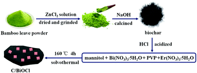
First, a certain number of bamboo leaves were washed with deionized water to remove the surface dust and a bamboo leaf powder was formed by smashing. The powder (8.0 g) was then dissolved in 350 mL of ZnCl2 solution (1.0 mol L−1), cleaned and filtered after mixing for 1 h. The above dried materials were ground evenly in the mortar and then transferred into a 50 mL beaker with adding 10 mL of deionized water. After keeping this solution under seal in a 60 °C oven for over 6 h, the product was smoothly filled into the porcelain boat and placed in a quartz tube furnace with a temperature from 30 °C to 750 °C and 5 °C min−1 of the rising rate for 2 h. Afterwards, the black powder that was biochar was dissolved into 300 mL of HCl (1 mol L−1) and stirred for 2 h. The biochar was washed to make it neutral and dried at 60 °C in an oven for 6 h. Then, 0.972 g of Bi(NO3)3·5H2O and 0.10 g PVP were initially dissolved in 50 mL of 0.1 M mannitol solution with vigorous stirring for 10 min. Then, 10 mL saturated NaCl aqueous solution was dropwise injected into the above mixed solution, followed by the addition of a certain amount of bicohar, yielding a uniform suspension. After another 10 min of agitation, the mixture was finally transferred into a Teflon-lined autoclave and subsequently heated at 160 °C for 4 h and then cooled to room temperature naturally. The precipitate was collected by centrifugation and washed with deionized water and ethanol for several times to remove residual ions. The final products were then dried at 60 °C for 6 h for further characterization. The weight ratios of biochar in C/BiOCl materials were 10 wt%, 15 wt% and 20 wt%, and the samples were named as 10C/BiOCl, 15C/BiOCl and 20C/BiOCl, respectively. The major fabrication process for C/BiOCl is shown in Scheme 1.2.3. Characterization
Powder X-ray diffraction (XRD) was used to identify the crystal structure of as-prepared samples, and the data were recorded on a Bruker D8 Advance X-ray diffractometer equipped with Cu-Kα radiation (λ = 1.54 Å). The transmission electron microscopy (TEM) and scanning electron microscopy (SEM) images were taken on FEI Tecnai G2 S-Twin operated at an acceleration voltage of 300 kV. Room-temperature UV-vis diffuse reflectance spectrum (DRS) was analyzed on Shimadzu UV-3600 using BaSO4 as the reflectance standard. The photoluminescence (PL) spectra for solid samples were measured by a Varian Cary Eclipse spectrometer with an excitation wavelength of 360 nm. X-ray photoelectron spectroscopy (XPS) valence spectra were conducted on a PHI 5700ESCA system with a monochromatic Al Kα source operated at 300 W.2.4. Adsorption and photocatalytic measurement
First, 50 mg sample and 100 mL TC-HCl solution (10 mg L−1) were added into a photocatalytic reaction bottle. The mixed solution was kept in the dark with continuous magnetic stirring. The aqueous solution reached adsorption–desorption equilibrium after it was magnetically stirred in dark. We turned on the 300 W Xe lamp with full-spectrum. Also, 5 mL of the sample solution was withdrawn and centrifuged to remove the photocatalyst in the irradiation interval of 15 min. The clarified solution was further analyzed on a UV-vis spectrometer at the characteristic absorption of λmax = 357 nm.3. Results and discussion
3.1. Morphology and structure of the samples
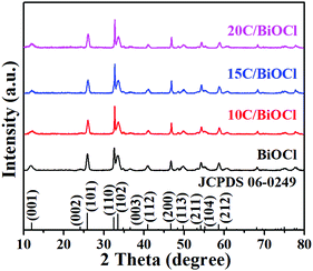
The crystalline nature and phase purity of the synthesized samples were investigated by XRD. As shown in Fig. 1, the as-prepared samples exhibit good XRD diffraction peaks. The peaks at 12.0°, 24.1°, 25.9°, 33.4°, 36.5°, 40.9°, 46.6°, 49.7°, 54.1°, 55.1° and 58.6° exactly match with the characteristic diffraction peaks of pristine BiOCl when compared with the standard card number for 06-0249 with (001), (002), (101), (102), (003), (112), and (200).31–35 It is worth noting that the peak of BiOCl did not change significantly in the composite. Therefore, after the introduction of biochar, BiOCl still maintained its good and stable crystalline structure. It is interesting to note that the image does not show any diffraction peaks of biochar. This is mainly because biochar has an amorphous structure and its diffraction peak intensity is lower as compared with that of BiOCl and thus has not appeared in the XRD patterns.3.2. TEM and HRTEM
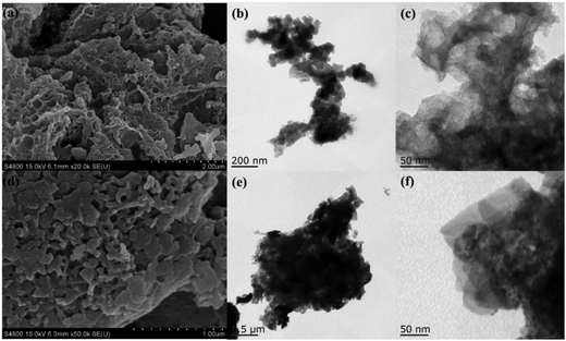
The morphological characteristics of biochar and 15C/BiOCl as well as their composite degree were investigated by SEM and TEM. In Fig. 2a, a simple SEM image of monomer biochar presents a larger size and pore-rich amorphous structure after a series of modified pyrolysis processes. The morphology characteristic of porous biochar is the key to a composite material in significantly increasing the adsorption. In addition, the rough surface characteristics of biochar are suitable for loading large amounts of BiOCl ultrathin nanosheets. As shown in Fig. 2b, biochar is amorphous and from the selected small range in Fig. 2b (Fig. 2c), it can be seen that biochar still has a subtle and evident porous structure on the surface. The relatively broad aperture distribution is in favor of adsorption at different degradation targets. Fig. 2d is the SEM image of 15C/BiOCl. According to Fig. 2e and f, it can be further found that BiOCl has been successfully loaded on the surface of biochar, and BiOCl still maintains its stable and good crystallinity. As a result, the pore structure of biochar does not change significantly after the introduction of BiOCl, and C/BiOCl not only has excellent adsorption, but also maintains the ultrathin structure.3.3. Optical absorption properties
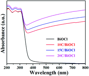
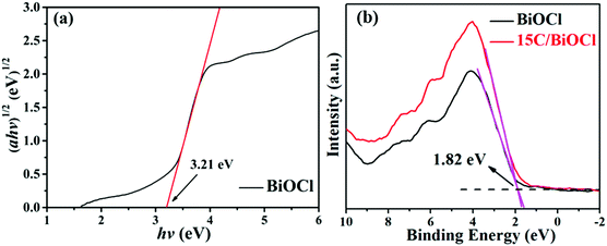
UV-vis absorption spectroscopy was further utilized to probe the optical absorption properties of the C/BiOCl materials (Fig. 3). It can be seen that the light absorption edge of the monomer BiOCl is at around 380 nm and it has a weak visible light excitation response. Due to the black character of biochar, all the composites have strong light absorbing capacity, which results in significant light absorption improvement in the visible light and long wavelength region. In the further observation, the characteristic absorption edge of BiOCl in the composite materials has a certain degree of redshift after the introduction of biochar. Considering that biochar is a kind of a fixed type of supporting material, the phenomenon of redshift can be attributed to the absorption intensity of surge over the visible region.3.4. PL spectra
It can be seen from Fig. 4a that all the samples exhibit a strong emission peak centered at around 460 nm and a shoulder at 550 nm. However, the PL intensity of BiOCl changed significantly after the introduction of biochar, and 15C/BiOCl showed better activity. The lower PL intensity suggested a higher separated efficiency.2,5,14 Therefore, the PL results further demonstrated that 15C/BiOCl has a higher separation rate of electron–hole pairs. The reason may be that biochar is a good electron acceptor, and the photoexcited electrons can have effective migration in the system, which improves the separation of the electron–hole pairs. Moreover, according to the collected data of the N2 adsorption–desorption isotherm (Fig. 4b), the specific surface areas of BiOCl and 15C/BiOCl are 9.18 and 35.97 m2 g−1, respectively. We analyzed that the enlarged specific surface area may originate from C, and the improved specific surface area will provide abundant reaction sites for enhancing the adsorption ability and degradation activity for TC-HCl.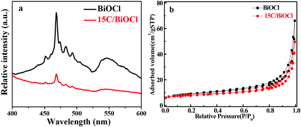 | ||
| Fig. 4 Solid PL emission spectra (a) and N2 adsorption–desorption isotherm (b) of BiOCl and 15C/BiOCl. | ||
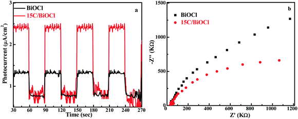
In addition, the photocurrent–time (I–t) experiment and electrochemical impedance spectroscopy (EIS) were conducted (Fig. 5). Notably, the photocurrent intensity for 15C/BiOCl was nearly 2.5 times higher than that of BiOCl. This suggested the more efficient separation of electron–hole pairs in 15C/BiOCl. Meanwhile, compared with the diameter of the arc radius for EIS, the arc radius for the electrode of 15C/BiOCl was smaller, suggesting that the incorporation of biochar could effectively accelerate charge transfer and enhance the TC-HCl degradation activity.
3.5. Photocatalytic performances
TC-HCl was selected as the degradation target to evaluate BiOCl performances. As shown in Fig. 6a, the adsorption performance of all composite materials increases after increasing the addition content of biochar, and all the samples reach adsorption equilibrium within 60 min in dark. Although there is still a certain gap between biochar and the BiOCl composite materials in the adsorption amount, the adsorbed amounts of the composite samples have been significantly increased compared with that of single BiOCl. This is mainly because biochar can produce loose pores after pyrolysis and provide more adsorption sites for target molecules. Specially, the adsorption sites are the most basic requirement in the photocatalytic reactions. Therefore, the introduction of biochar can guarantee an effective contact between the active radicals and TC-HCl during the photocatalytic process. It can be seen from Fig. 6b that single BiOCl has limited photocatalytic activity for TC-HCl. However, after the decoration of biochar on it, the photocatalytic ability significantly increased. Obviously, when the amount of biochar was 15 wt%, the composite exhibited the highest photocatalytic activity, and the degradation rate was 71.8%. Therefore, the introduction of biochar requires scientific control, which can ensure stable improvement in the photolysis rate. Further observations showed that the photolysis behavior was consistent with the first-order kinetic process.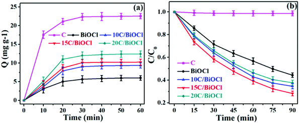 | ||
| Fig. 6 (a) Dynamic curves of TC-HCl absorption over different samples in the dark, (b) TC-HCl degradation dynamic curves over different samples. | ||
It can be clearly seen from Fig. 7a that 15C/BiOCl has an optimized performance compared with pristine BiOCl because the value of its constant is maximum (K = 0.0139). Fig. 7b shows the cycle curve diagram of 15C/BiOCl over the photodegradation of TC-HCl. After 5 cycles of experiments, the degradation rate still remains around 70%. Moreover, the XRD analysis results of 15C/BiOCl before and after reaction are shown in Fig. 7c. The characteristic peaks of 15C/BiOCl are almost unchanged, indicating that 15C/BiOCl has better stability.
 | ||
| Fig. 7 (a) Plots of ln(C0/C) versus time and reaction rate constant k, (b) recycle experiments, (c) XRD patterns of fresh and used 15C/BiOCl. | ||
HPLC-MS was carried out to identify the TC-HCl intermediates during the photodegradation reaction. As shown in Fig. 8a–c, the peak of TC-HCl (m/z = 443) decreases obviously and almost disappears after the degradation of 90 min. The results prove that TC-HCl must have decomposed into small molecules.
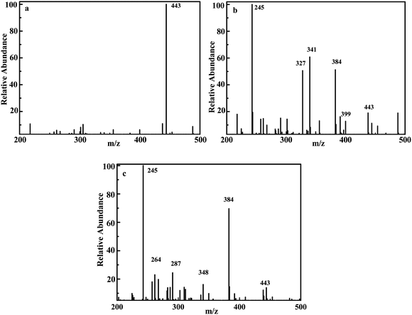 | ||
| Fig. 8 m/z of degrading TC-HCl over 15C/BiOCl: initial solution (a), degradation in 45 min (b), degradation in 90 min (c). | ||
3.6. Possible photocatalytic mechanism
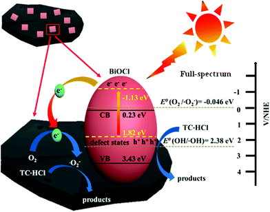
| BiOCl + hν → h+(BiOCl) + e−(BiOCl) | (1) |
| e−(BiOCl) → e−(C) | (2) |
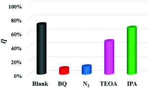
| O2(C) + e−(C) → ˙O2−(C) | (3) |
| ˙O2−(C) + TC-HCL → degraded products | (4) |
| h+(BiOCl) + TC-HCl → degraded products | (5) |
4. Conclusion
In this work, a novel 2D photocatalyst, namely, C/BiOCl was constructed via a one-pot hybridization method. The BiOCl ultrathin nanosheets modified by biochar could provide a reliable and fast transfer path for photoexcited electrons, effectively inhibiting their invalid annihilation. Moreover, the stronger adsorption characteristics of biochar also provided more active sites to be in contact with the TC-HCl targets in a complex system. The maximum adsorption quantity of all composites was above 9.36 mg g−1 in a dark reaction within 60 min. At the same time, when the biochar content was 15 wt%, this C/BiOCl exhibited the best photocatalytic activity, and its degradation efficiency could reach to 71.8% within 90 min. This work may provide a new path for enhancing the photocatalytic activity of BiOCl by introducing biochar.Conflicts of interest
All the authors declare that they have no conflict of interest.Acknowledgements
This work was supported by the National Natural Science Foundation of China (No. 21676115, 21908080 and U1662125), the Natural Science Foundation of Jiangsu Province (No. BK20190862 and BK20181231). China Postdoctoral Science Foundation Funded Project (No. 2019M651729).References
- B. Lin, G. Yang and L. Wang, Angew. Chem., Int. Ed., 2019, 58, 4587–4591 CrossRef CAS.
- Z. Zhu, X. Tang, P. Huo, M. Song, W. Shi, Z. Lu and Y. Yan, J. Phys. Chem. C, 2016, 120, 27250–27258 CrossRef CAS.
- F. Pincella, K. Isozaki and K. Miki, Light: Sci. Appl., 2014, 3, e133–e139 CrossRef CAS.
- R. R. Jiang, G. H. Lu, D. H. Wu, Z. H. Yan, R. R. Zhou and X. H. Bao, Chem. Eng. J., 2019, 374, 79–90 CrossRef CAS.
- B. Lin, J. Li, B. Xu, X. Yan, B. Yang, J. Wei and G. Yang, Appl. Catal., B, 2019, 243, 94–105 CrossRef CAS.
- C. Ma, D. Wu, X. Yao, X. Liu, M. Wei, Y. Liu, Z. Ma, P. Huo and Y. Yan, J. Alloys Compd., 2017, 712, 486–493 CrossRef CAS.
- S. Ning, L. Ding, Z. Lin, Q. Lin, H. Zhang, J. Long and X. Wang, Appl. Catal., B, 2016, 185, 203–212 CrossRef CAS.
- T. Yatsui, T. Tsuboi and M. Yamaguchi, Light: Sci. Appl., 2016, 5, e16054–e16061 CrossRef CAS PubMed.
- R. Fu, X. Zeng, L. Ma, S. Gao, Q. Wang, Y. Dai and J. Lu, J. Power Sources, 2016, 312, 12–22 CrossRef CAS.
- S. Bai, X. Li, Q. Kong, R. Long, C. Wang, J. Jiang and Y. Xiong, Adv. Mater., 2015, 27, 3444–3452 CrossRef CAS.
- X. Chen, S. Shen, L. Guo and S. S. Mao, Chem. Rev., 2010, 110, 6503 CrossRef CAS PubMed.
- L. Liu and X. Chen, Chem. Rev., 2014, 114, 9890–9918 CrossRef CAS PubMed.
- Y. Sun, S. Gao, F. Lei and Y. Xie, Chem. Soc. Rev., 2015, 44, 623–636 RSC.
- J. Wang, L. Tang, G. Zeng, Y. Deng and Y. Liu, Appl. Catal., B, 2017, 209, 285–294 CrossRef CAS.
- M. Osada and T. Sasaki, Adv. Mater., 2012, 24, 210–217 CrossRef CAS PubMed.
- L. Li, H. Lin, S. Qiao, Y. Z. Huang and J. Y. Li, Light: Sci. Appl., 2018, 7, 17138–17146 CrossRef CAS PubMed.
- Z. Zhu, Z. Lu, X. Zhao and Y. Yan, RSC Adv., 2015, 5, 40726–40736 RSC.
- L. Liang, F. Lei, S. Gao, J. Wu and S. Wei, Angew. Chem., Int. Ed., 2016, 54, 13971–13974 CrossRef PubMed.
- Y. Sun, Z. Sun, S. Gao, H. Cheng, Q. Liu, J. Piao, T. Yao and S. Wei, Nat. Commun., 2012, 3, 1057 CrossRef PubMed.
- J. Bonefacino, H. Y. Tam, T. S. Glen, X. Cheng, C. F. Pun and J. Wang, Light: Sci. Appl., 2018, 7, 17162–17171 CrossRef PubMed.
- W. Zhou, Z. Yin, Y. Du, X. Huang, Z. Zeng and H. Zhang, Small, 2013, 9, 140–147 CrossRef CAS PubMed.
- G. Liu, P. Niu, C. Sun, S. Smith, Z. Chen and G. Lu, J. Am. Chem. Soc., 2010, 132, 11642–11648 CrossRef CAS PubMed.
- Y. Ao, K. Wang, P. Wang, C. Wang and J. Hou, RSC Adv., 2016, 6, 48599–48609 RSC.
- Z. He, Y. Shi, C. Gao, L. Wen, J. Chen and S. Song, J. Phys. Chem. C, 2014, 118, 389–398 CrossRef CAS.
- Y. Zhu, Z. Li, C. DiMarco1 and N. Yu, Light: Sci. Appl., 2018, 7, 67–78 CrossRef.
- J. Jiang, K. Zhao, X. Xiao and L. Zhang, J. Am. Chem. Soc., 2012, 134, 4473–4476 CrossRef CAS PubMed.
- H. Li, J. Shi, K. Zhao and L. Zhangt, Nanoscale, 2014, 6, 14168–14173 RSC.
- X. Zhang, X. B. Wang, L. L. Long, W. W. Li and H. Q. Yu, ACS Appl. Mater. Interfaces, 2014, 6, 7766–7772 CrossRef CAS PubMed.
- X. Ma, C. Y. Dai, L. Yu and B. B. Huang, Light: Sci. Appl., 2017, 5, e16017–e16030 CrossRef PubMed.
- K. Zhao, L. Zhang, J. Wang, Q. Li, W. He and J. Yin, J. Am. Chem. Soc., 2013, 135, 15750–15753 CrossRef CAS.
- J. Jiang, L. Zhang, H. Li, W. He and J. J. Yin, Nanoscale, 2013, 5, 10573–10581 RSC.
- H. Wang, L. Zhang, Z. Chen, J. Hu, S. Li, Z. Wang, J. Liu and X. Wang, Chem. Soc. Rev., 2014, 43, 5234–5244 RSC.
- J. Li, Y. Yu and L. Zhang, Nanoscale, 2014, 6, 8473–8488 RSC.
- K. Sugioka and Y. Cheng, Light: Sci. Appl., 2014, 3, e149 CrossRef CAS.
- H. Zhao, Y. Zhang, G. Li, F. Tian, H. Tang and R. Chen, RSC Adv., 2016, 6, 7772–7779 RSC.
- X. Zhang, Z. Ai, A. F. Jia and L. Zhang, J. Phys. Chem. C, 2008, 112, 747–753 CrossRef CAS.
- H. Cheng, B. Huang and Y. Dai, Nanoscale, 2014, 6, 2009–2026 RSC.
- H. Wen, X. Ru, T. Xi, J. Jie and W. Wei, Light: Sci. Appl., 2017, 6, e17113 CrossRef.
- Q. Yuan, C. Lang, X. Miao and H. Jie, Chem. Eng. J., 2014, 255, 394–402 CrossRef CAS.
- D. Jiang, T. Wang, Q. Xu, D. Li, S. Meng and M. Chen, Appl. Catal., B, 2017, 201, 617–628 CrossRef CAS.
- S. Vasheghani, T. Veal, J. Mudd, D. Scanlon, G. Watson, O. Bierwagen and M. Mconville, Phys. Rev. B: Condens. Matter Mater. Phys., 2014, 90, 155413 CrossRef.
- T. Yatsui, T. Tsuboi and M. Yamaguchi, Light: Sci. Appl., 2016, 5, e16054–e16061 CrossRef CAS PubMed.
- H. Shen, J. Wang, J. Jiang, B. Luo, B. Mao and W. Shi, Chem. Eng. J., 2017, 313, 508–517 CrossRef CAS.
- C. Li, G. Chen, J. Sun, H. Dong, Y. Wang and C. Lv, Appl. Catal., B, 2014, 160–161, 383–389 CrossRef CAS.
- D. Yang, H. Liu, Z. Zheng, X. Ke and H. Zhu, J. Am. Chem. Soc., 2009, 131, 17885–17889 CrossRef CAS PubMed.
- E. Maguid, I. Yulevich, M. Yannai, V. Kleiner and E. Hasman, Light: Sci. Appl., 2017, 6, e17027 CrossRef PubMed.
- J. Li, Y. Zhao, M. Xia, H. An, H. Bai, J. Wei, B. Yang and G. Yang, Appl. Catal., B, 2020, 261, 118244 CrossRef.
- X. Yan, B. Xu, X. Yang, J. Wei, B. Yang, L. Zhao and G. Yang, Appl. Catal., B, 2019, 256, 117812 CrossRef CAS.
| This journal is © The Royal Society of Chemistry and the Centre National de la Recherche Scientifique 2020 |

