DOI:
10.1039/C9NJ05172D
(Paper)
New J. Chem., 2020,
44, 95-101
Revealing the potential application of chiral covalent organic frameworks in CO2 adsorption and separation†
Received
14th October 2019
, Accepted 18th November 2019
First published on 19th November 2019
Abstract
The adsorption and separation abilities of gases (including CO2, CH4, N2, and H2) in a series of chiral COFs (CCOFs) were studied using the Grand canonical Monte Carlo (GCMC) method, periodic density functional theory (DFT) (PBE functional) calculations and accurate dispersion corrected double-hybrid DHDF-D3 to explore the potential application of recently synthesized chiral COFs (Han et al., J. Am. Chem. Soc., 2018, 140, 892–895 and Han et al., J. Am. Chem. Soc., 2017, 139, 8693–8697). In contrast to four classical structures (including IRMOF-1, UMCM-1, COF-5, and ZIF-8), CCOF6 shows a better CO2 adsorption capacity at 298 K in a wide range of pressure from 0 to 100 kPa. More importantly, the selectivity of CO2 over N2, CH4 and H2 in CCOF6 is obviously greater than that of other classic porous materials. GCMC simulation demonstrates that the CO2 molecules prefer the smaller B1 channel in CCOF6 at pressure lower than 10 kPa; however, there is no obvious preferential adsorption site in CCOF5. To better understand the mechanism of CO2 adsorption in CCOFs, the interaction energy between CO2 and CCOFs was calculated by the double-hybrid DFT-D3, confirming the preferred adsorption sites in CCOF6 due to the proper narrow channel and the charge transfer from CO2 to CCOF6. Our well established theoretical calculation reveals that CCOF6, with promising CO2 adsorption and selectivity properties, has the potential to be an excellent material for CO2 adsorption and separation.
Introduction
Covalent organic frameworks (COFs)1,2 are novel porous crystalline materials3–6 composed of light elements such as carbon, hydrogen, oxygen, nitrogen and boron linked by covalent bonds. They have a great potential for application in the fields of catalysis,7,8 adsorption,9–11 separation,12,13etc.14–16 owing to their high stability, low density, large surface area, and tunable pore sizes. Previous studies have reported that COFs exhibit outstanding abilities in terms of gas adsorption and separation. Furukawa and Yaghi found that COFs showed excellent adsorption capacity for carbon dioxide, hydrogen, and methane among the most common carbon materials.17 A perfluorinated covalent triazine-based framework (FTCF-1) demonstrated not only exceptionally high CO2 storage capacity but also ideal separation of CO2 from N2 reported by Zhao et al..18 Baldwin et al. discovered that 3D DBA-COFs expressed high uptake for ethane and ethylene gas.19
Recently, Han et al.20,21 synthetized a new series of novel chiral COFs (CCOFs) which feature an enantioselective process. Furthermore, the CCOFs show permanent porosity and high stability in water and most organic solvents, which draw our intensive attention, and spark our interest in exploring their adsorption and separation properties. It is vitally important to search for the potential application of already synthesized, or even the hypothetical materials, with the aim to identify promising materials and reveal the structure–property relations with the aid of the molecular modeling method.22 Our group performed several interesting modeling studies on novel porous materials. For example, Pang et al. displayed that thiophene-based CPTs were suitable for the application of H2 storage and its purification.23 Zhou et al. reported that CAU-17 and functionalized CAU-17 can selectively adsorb CH4 over H2.24 Guan et al. established a screening method to analyze the content of activated pores in COFs and this approach can be expanded to be automated for high-throughput screening of a lot of porous crystalline materials, especially for predicting their adsorption potential.25 Zhang et al. considered that spiroborate-linked ICOFs were likely five-fold interpenetrating models and ICOFs are promising CH4 storage materials.26
In this work, we explored the CO2, CH4, N2, and H2 adsorption capacity of CCOFs and investigated the CH4/H2, CH4/N2, CO2/N2, CO2/CH4 and CO2/H2 separating performance in CCOF4, CCOF5, and CCOF6 by the combination of GCMC simulations and DFT calculations. Due to the appropriate narrow channel and the charge transfer between CO2 and CCOF6, CCOF6 shows the preferred CO2 adsorption sites at low pressure. We find that CCOF6 is a good candidate for CO2 adsorption and separation by comparing it with other CCOFs and 4 classic porous materials.
Models and computational methods
CCOF structures
The models of a series of CCOFs were taken from the reference20,21 and are shown in Fig. 1. The detailed structural parameters of the unit cells in CCOFs are listed in Table S1 (ESI†). Fig. 1a, c, and e display the unit cell of CCOF4, CCOF5, and CCOF6, respectively. And Fig. 1b, d and f display the supercell of CCOF4, CCOF5, and CCOF6 in the form of 2 × 2 × 3, 2 × 2 × 2, and 2 × 2 × 2 unit cell, respectively, as a modeling box. CCOF4 shows a 1D channel, and then CCOF5 and CCOF6 show 3D channels, which are represented in the green surface. CCOF5 and CCOF6 have the same topology of the framework. The A1 channel in CCOF5 is surrounded by benzene rings, while the B1 channel in CCOF6 contains ketones with the exposed oxygen. The structures of the typical porous materials such as IRMOF-1,27 UMCM-1,28 COF-5,1 and ZIF-829 were taken from the literature for comparison.
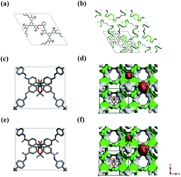 |
| | Fig. 1 The structures of (a and b) CCOF4, (c and d) CCOF5, and (e and f) CCOF6, and H atoms were omitted for clarity. | |
Potential models
To describe the adsorption properties of various gas molecules in the concerned porous materials, the following models were adopted. CO2 was considered as a three-site rigid linear molecule, and its quadrupole moment was described by a partial charge model.30 For CH4, N2, and H2 molecules, we used a spherical united-atom model.31–33 The above potential models have been employed well in previous work.34 Given that the Dreiding force field35 could successfully provide accurate prediction of gas adsorption and separation,36 it was applied to the potential parameters of framework atoms. All the LJ interaction parameters between adsorbates and adsorbents were calculated by Lorentz–Berthelot mixing rules, as shown in eqn (1) and (2):37All the potential parameters with partial charges are listed in Table 1. As for the charge of the frameworks, we made use of the QEq38 method based on Ewald summation.
Table 1 Lennard-Jones potential parameters for adsorbates and adsorbents
| Species |
Site |
ε/kB (K) |
σ (Å) |
q (e) |
| CH4 |
CH4 |
148.000 |
3.730 |
|
| H2 |
H2 |
36.700 |
2.958 |
|
| CO2 |
C |
27.000 |
2.800 |
+0.70 |
| O |
79.000 |
3.050 |
−0.35 |
| N2 |
N2 |
94.950 |
3.549 |
|
| C |
47.900 |
3.470 |
|
| H |
7.660 |
2.850 |
|
| Adsorbents |
O |
48.158 |
3.033 |
|
| N |
39.007 |
3.263 |
|
| B |
47.806 |
3.580 |
|
| Zn |
27.718 |
4.450 |
|
GCMC simulations
All GCMC simulations were calculated by using the MUSIC code.39 The cutoff radius was set to 12.0 Å, and the porous frameworks were expended into the supercell greater than 24.0 Å along each dimension. There were 4 × 10⁷ trial moves during each simulation, including the first 2 × 10⁷ steps for equilibrium and the rest 2 × 10⁷ steps for data collection. The experimental data usually provide excess uptake Nex, however GCMC simulations provide absolute uptake Nabs. Therefore, we should convert the absolute uptake to excess uptake for contrast as given in eqn (3)where ρg is the density of bulk gas which is calculated from the PREOS,40 and Vg is the effective volume of the adsorbent. Vg is obtained using the following eqn (4)41where T, R, and P represent the temperature, gas constant, and pressure, respectively. And Nm is the number of adsorbent probe molecules per molar mass mm of the framework, which is obtained by GCMC simulation of non-adsorbed helium in the absorbent at low pressure and room temperature.42
To reflect the intensity of force between gas molecules and the adsorbed phase, Qst is expressed by eqn (5)
where
R is the universal gas constant,
T is the temperature,
N is the number of adsorbed particles and
U is the energy of the sorbate in the adsorbed state which consists of adsorbate–adsorbate and adsorbate–adsorbent interactions.
The adsorption selectivity refers to the ability of an adsorbate to preferentially adsorb certain substances due to its pore topology and pore-surface character. The adsorption selectivity of compound i relative to compound j in a mixture can be calculated using eqn (6)
| | | Sads(i/j) = (xi/xj)/(yi/yj) | (6) |
where
xi and
yi are the mole fractions of compound
i in the adsorbed phase and the bulk phase, respectively.
DFT calculations
It is critical to obtain the interaction energy (Eint) between gas molecules and frameworks using DFT calculations43 so as to further study the adsorption mechanism. The interaction energy is calculated using eqn (7)| | | Eint = Etotal − Ea − Eb | (7) |
where Etotal is the total energy of the gas molecule and the framework, Ea is the energy of the gas molecule alone, and Eb is the energy of the framework alone.
The potential energy surface of CO2 in the channel of CCOFs was scanned using periodic DFT at the PBE-D244,45/DNP46 level by Dmol3 module of Materials Studio software, where the two oxygen atoms of carbon dioxide were relaxed. In addition, a high accuracy method at the B2PLYP-D347,48/def2-tZVPP49 level was employed to evaluate the interaction and NBO charge50 transfer between CO2 and the efficiency fragment cut from the pore surface of the CCOFs using the Gaussian 09 package.51
Results and discussion
Verification of the force field
Fig. 2 shows the comparison of the predicted adsorption isotherms of N2 in (a) CCOF4, (b) CCOF5, and (c) CCOF6 at 77 K with the experimental data.16,17 The deviations for these N2 adsorption isotherms in the three materials are acceptable as perfect crystals are employed in the simulation, while pore blocking, crystal defects, and impurity influence the isotherms in actual measurements.21,47 As a result, the Dreiding force field is adopted in the GCMC simulations.
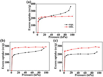 |
| | Fig. 2 Adsorption isotherms of N2 in (a) CCOF4, (b) CCOF5, and (c) CCOF6 at 77 K. The black lines represent the experimental data,16,17 and red lines represent simulation results. | |
Adsorption of pure gases
In order to evaluate the abilities of the CCOFs for pure gas adsorption (including N2, H2, CH4, and CO2), the comparison of adsorption isotherms with several classic porous materials (including COF-5, IRMOF-1, ZIF-8 and UMCM-1) is shown in Fig. 3. From Fig. 3a, we can determine that the N2 loading of CCOF5 and CCOF6 is slightly higher than that in other structures. In terms of H2 adsorption, the CCOF6 structure with the most H2 loading (0.5 cc g−1 at a pressure of 100 kPa) in the CCOFs is only ranked third in all the selected structures, as shown in Fig. 3b. Impressively, CCOF5 and CCOF6 show extremely high CH4 and CO2 uptakes when compared with other frameworks. The high gas uptake can be attributed to the strong interactions between the gas molecules and the CCOF6. And, it is very clear that the CO2 adsorption capacity of CCOF6 is much higher than that in all structures. Moreover, the excess uptake of N2, H2, CH4, and CO2 in CCOF6 is in the order of H2 (0.50 cc g−1) < N2 (6.68 cc g−1) < CH4 (30.42 cc g−1) < CO2 (116.36 cc g−1) at 100 kPa. That is to say, the excess uptake of CO2 is significantly greater than other pure gas uptake. As shown in Fig. 3d, the CO2 uptake is larger than 110 cc g−1, which is much higher than that of the other porous materials including CCOFs and classic materials. As a result, CCOF6 exhibits a large amount of CO2 adsorption and is expected to be a promising CO2 adsorbent.
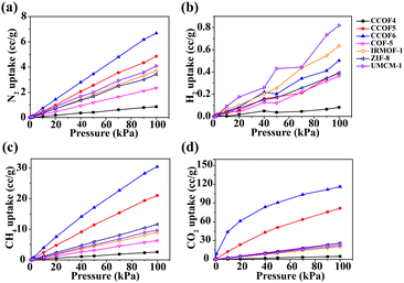 |
| | Fig. 3 Comparison of adsorption isotherms of pure (a) N2, (b) H2, (c) CH4, and (d) CO2 in CCOFs with several typical frameworks at 298 K. | |
To better understand the pure gas adsorption in porous materials, we calculated the isosteric heats of various gases as shown in Fig. 4. It can be seen that the CO2 isosteric heat in CCOF6 is the largest within the selected pressure range as shown in Fig. 4d. This proves that CCOF6 has strong ability to adsorb CO2. Overall, it can be found that the isosteric heats of pure gases in CCOF6 follow the order of H2 (6.88 kJ mol−1) < N2 (14.74 kJ mol−1) < CH4 (21.03 kJ mol−1) < CO2 (33.36 kJ mol−1) at 100 kPa, which is consistent with the adsorption capacities of pure gases under the same conditions. And the result revealed that the interaction between CO2 and the frameworks is stronger than that of other gases. Apparently, the biased affinity of CCOF6 for different gases demonstrates that CCOF6 may be a promising candidate for the CO2 separation.
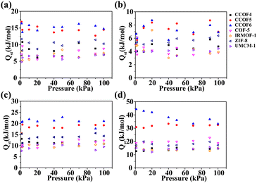 |
| | Fig. 4 Isosteric heats of (a) N2, (b) H2, (c) CH4, and (d) CO2 in CCOFs and some typical frameworks at 298 K. | |
Separation of binary gases
Fig. 5 shows the adsorption selectivity of the five mixtures in the selected classic frameworks and CCOFs at 298 K. To meet the practical applications of all kinds of gases, the different mole ratios of CH4/H2, CH4/N2, CO2/N2, CO2/CH4, and CO2/H2 selected are 50![[thin space (1/6-em)]](https://www.rsc.org/images/entities/char_2009.gif) :
:![[thin space (1/6-em)]](https://www.rsc.org/images/entities/char_2009.gif) 50, 50
50, 50![[thin space (1/6-em)]](https://www.rsc.org/images/entities/char_2009.gif) :
:![[thin space (1/6-em)]](https://www.rsc.org/images/entities/char_2009.gif) 50, 15
50, 15![[thin space (1/6-em)]](https://www.rsc.org/images/entities/char_2009.gif) :
:![[thin space (1/6-em)]](https://www.rsc.org/images/entities/char_2009.gif) 85, 15
85, 15![[thin space (1/6-em)]](https://www.rsc.org/images/entities/char_2009.gif) :
:![[thin space (1/6-em)]](https://www.rsc.org/images/entities/char_2009.gif) 85, and 20
85, and 20![[thin space (1/6-em)]](https://www.rsc.org/images/entities/char_2009.gif) :
:![[thin space (1/6-em)]](https://www.rsc.org/images/entities/char_2009.gif) 80, respectively. As shown in Fig. 5a and b, the selectivity of CH4/H2 and CH4/N2 in CCOF5 and CCOF6 is slightly higher than that of others and these values remain nearly constant with increasing pressure. Furthermore, it can be obviously found that the selectivity of CO2/N2, CO2/CH4, and CO2/H2 in CCOF6 and CCOF5 is greater than that in other frameworks from Fig. 5c, d and e. In other words, CCOF5 and CCOF6 have a great ability for CO2 separation over H2, N2, and CH4. In particular, the selectivity of CO2/N2, CO2/CH4 and CO2/H2 in CCOF6 is much higher than that of other materials including CCOF5. Meanwhile, it is observed that the selectivity of CO2/N2 and CO2/CH4 decreases with the increasing pressure, and the selectivity of CO2/H2 initially decreases with increasing pressure and then reaches a platform after 70 kPa. This phenomenon for the decline at first can be explained by the following. At low pressure, CO2 molecules preferentially occupied the CCOF6 channels. With the increase of pressure, there are fewer and fewer locations for adsorption of CO2. Consequently, the selectivity decreases accordingly. Overall, the selectivity for binary gases in CCOF6 is in the order CH4/N2 (4.67) < CO2/CH4 (14.35) < CH4/H2 (44.18) < CO2/N2 (73.60) < CO2/H2 (536.26) at 100 kPa. In a word, these results indicate that CCOF6 could be a promising candidate for CO2 separation over N2, CH4, and H2.
80, respectively. As shown in Fig. 5a and b, the selectivity of CH4/H2 and CH4/N2 in CCOF5 and CCOF6 is slightly higher than that of others and these values remain nearly constant with increasing pressure. Furthermore, it can be obviously found that the selectivity of CO2/N2, CO2/CH4, and CO2/H2 in CCOF6 and CCOF5 is greater than that in other frameworks from Fig. 5c, d and e. In other words, CCOF5 and CCOF6 have a great ability for CO2 separation over H2, N2, and CH4. In particular, the selectivity of CO2/N2, CO2/CH4 and CO2/H2 in CCOF6 is much higher than that of other materials including CCOF5. Meanwhile, it is observed that the selectivity of CO2/N2 and CO2/CH4 decreases with the increasing pressure, and the selectivity of CO2/H2 initially decreases with increasing pressure and then reaches a platform after 70 kPa. This phenomenon for the decline at first can be explained by the following. At low pressure, CO2 molecules preferentially occupied the CCOF6 channels. With the increase of pressure, there are fewer and fewer locations for adsorption of CO2. Consequently, the selectivity decreases accordingly. Overall, the selectivity for binary gases in CCOF6 is in the order CH4/N2 (4.67) < CO2/CH4 (14.35) < CH4/H2 (44.18) < CO2/N2 (73.60) < CO2/H2 (536.26) at 100 kPa. In a word, these results indicate that CCOF6 could be a promising candidate for CO2 separation over N2, CH4, and H2.
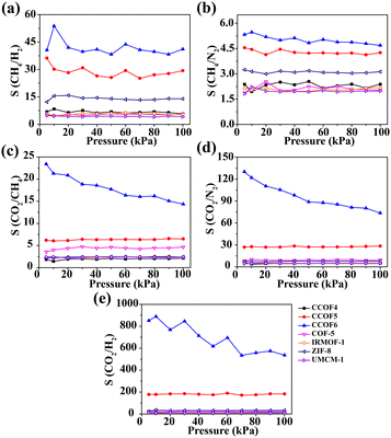 |
| | Fig. 5 Adsorption selectivity for the binary mixtures at 298 K. (a) CH4/H2, (b) CH4/N2, (c) CO2/N2, (d) CO2/CH4 and (e) CO2/H2. | |
Preferential adsorption sites
In efforts to study the CO2 adsorption mechanism, we provided the snapshots of CO2 in CCOF5 and CCOF6 at 298 K at different pressures, as shown in Fig. 6. At a pressure of 1 kPa, the B1 channels adsorb more CO2 molecules than B2 channels in CCOF6, whereas the amount of CO2 molecules adsorbed by the A1 and A2 channels of CCOF5 is similar. And so, the B1 channel is the preferential adsorption site of CO2 in CCOF6, while CCOF5 does not possess the obvious preferential adsorption site of CO2. As the pressure increases, the amount of adsorption per channel becomes more and more. It can be seen from Fig. 6b that the adsorption amount of CO2 is greatly increased from 1 kPa to 10 kPa, which is consistent with the results of the CO2 adsorption isotherm of CCOF6 in Fig. 3d. In addition, H2, N2, and CH4 are randomly distributed in each of the channels of CCOF5 and CCOF6 at low pressures from Fig. S1 and S2 (ESI†), so there is no obvious preferential adsorption site for H2, N2, and CH4. It can be concluded that there is an excellent CO2 separation of CCOF6 in binary gases.
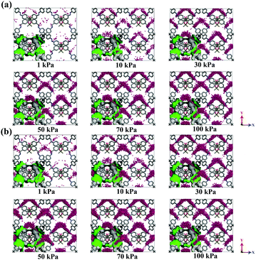 |
| | Fig. 6 Snapshots of CO2 in CCOF5 (a) and CCOF6 (b) at T = 298 K at different pressures. | |
Interaction between gases and frameworks
With the aim of deeply investigating the microscopy mechanism, periodic DFT calculations at the PBE-D2/DNP level were performed to describe the interaction between gases and frameworks. The profile of Eint of CO2 in two planes with z = 0.5 and y = 0.5 of CCOF5 and CCOF6 is shown in Fig. 7. The darker red color is found, and the stronger interaction between the gases and CCOFs is shown in Fig. 7. Fig. 7a and c clearly show that the A1 and A2 channels of CCOF5 show a similar maximum interaction energy to CO2 with the Eint in the range of −4.539 ∼−5.577 kcal mol−1, while the maximum interaction energy between CO2 molecules and the B1 channels (−9.893 kcal mol−1) is higher than the maximum interaction energy between the CO2 molecules and the B2 channels (−5.477 kcal mol−1). In Fig. 7a and c, the maximum interaction of CO2 in the narrow B1 channels of CCOF6 (−9.893 kcal mol−1) is greater than the maximum interaction in the A1 channels of CCOF5 (−4.539 kcal mol−1), and we can also find that the maximum interaction of CO2 in the narrow B1 channels of CCOF6 (−9.584 kcal mol−1) is larger than the maximum interaction of CO2 in the A1 channels of CCOF5 (−5.438 kcal mol−1) from Fig. 7b and d, which are in line with the low-pressure gas distribution from GCMC simulations in Fig. 6. The main difference between the B1 channel of CCOF6 and the A1 channel of CCOF5 is that the B1 channel of CCOF6 has no oxygen atoms, but the A1 channel of CCOF5 has. The bulky oxygen atoms in the B1 channel of CCOF6 can narrow the channel to fit CO2 molecules, resulting in higher interaction energies between them. Moreover, the exposed oxygen atoms may provide induction force to the CO2 molecules, leading to the enhancement of interaction between them. As a result, an accurate calculation and detailed discussion on the interaction between CO2 and the key fragment of channels should be performed.
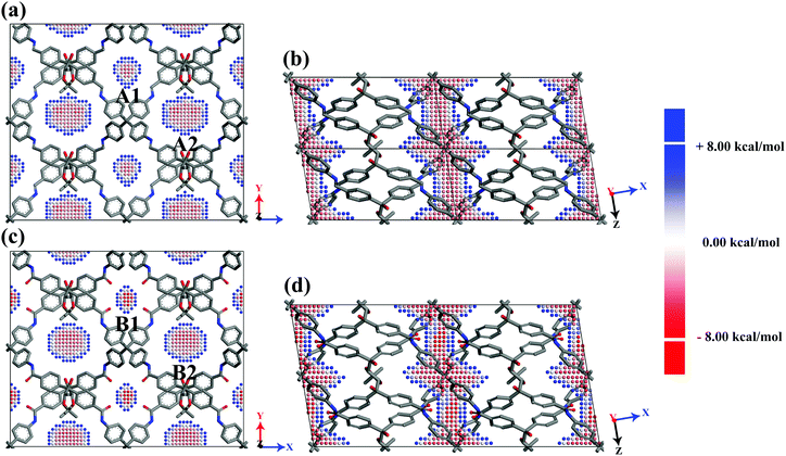 |
| | Fig. 7 The profiles of Eint of CO2 in two planes with z = 0.5 and y = 0.5 of CCOF5 (a and b) and CCOF6 (c and d) in the display style of 2 × 2 × 1 (a and c) and 2 × 1 × 2 (b and d) on the basis of the unit cell. The points are centers of C atoms of CO2 molecules and the distance of each C atom is 0.5 Å. The colour represents the framework–gas interaction energy. All H atoms are omitted for the sake of clarity. | |
The accurate method at the B2PLYP-D3/def2-TZVPP level was used to calculate the interaction energy between the key fragment of CCOFs and CO2. The most stable ones are shown in Fig. 8, and the metastable structures and interaction energies are shown in Fig. S3 (ESI†). The distance of the CO2 molecule to the segment of CCOF5 is somewhat longer than that to the segment of CCOF6, whilst the maximum interaction energy of CO2 to the segment of CCOF5 (−5.265 kcal mol−1) is smaller than that to the segment of CCOF6 (−6.161 kcal mol−1). It can be concluded that CCOF6 and CO2 have stronger interaction. Furthermore, the NBO charges of the skeletons interacting with the CO2 molecule shown in Fig. 8 were calculated to explore the effect of charge on the interaction at the B2PLYP-D3/def2-TZVPP level. As listed in Table 2, the C–CO2 charge transferred from free CO2 to the one adsorbed in CCOF6 is 0.02103 e, which is greater than the corresponding one in CCOF5 (0.01516 e). And the charge reduction of two oxygen atoms of CO2 from free CO2 to the one adsorbed in CCOF6 (0.02300 e) is more than that of CCOF5 (0.01544 e). Meanwhile, the total charge transfer of CO2 upon adsorption in CCOF6 (−0.00197 e) is more remarkable than that upon adsorption in CCOF5 (−0.00028 e). This illustrates that the large charge transfer of CO2 in CCOF6 over CCOF5 is a reason for the greater interaction energy of CCOF6 with CO2 than CCOF5. Very interestingly, the transferred charge of O17 in CCOF6 upon CO2 adsorption is the same as the transferred charge of N3 in CCOF5 with the amount of 0.0203 e, which is the maximum transferred charge in the CCOF fragments. One should note that, the charge of the O17 atom in CCOF6 is larger than the charge of the N3 atom in CCOF5, which will result in a greater electrostatic interaction of the O17 atom to CO2 in CCOF6 than the N3 atom to CO2 in CCOF5. It is indicated that the strong electrostatic interaction between the additional O atom of CCOF6 and CO2 is a cause for the increasing interaction energy. All in all, CCOF6 has a closer distance, more charge transfer, and larger interaction with CO2, which endows CCOF6 with promising CO2 adsorption and separation properties when compared with CCOF5.
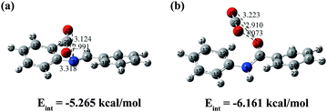 |
| | Fig. 8 The conformations and interaction energies of the most stable dimers of the segment of CCOF5-CO2 (a) and CCOF6-CO2 (b) with the distances shown in angstroms. | |
Table 2 (a) Calculated partial NBO charges (e) in isolated CCOF5, CO2, and CCOF5 interacting with CO2. (b) Calculated partial NBO charges (e) in isolated CCOF6, CO2, and CCOF6 interacting with CO2
| (a) |
|
|
CCOF5 |
CO2 |
CCOF5 + CO2 |
| N3 |
−0.4452 |
|
−0.4655 |
| C26 |
|
1.0908 |
1.1059 |
| O27 |
|
−0.5454 |
−0.5496 |
| O28 |
|
−0.5454 |
−0.5566 |
| (b) |
|
|
CCOF6 |
CO2 |
CCOF6 + CO2 |
| O17 |
−0.6284 |
|
−0.6487 |
| C27 |
|
1.0908 |
1.1118 |
| O28 |
|
−0.5454 |
−0.5455 |
| O29 |
|
−0.5454 |
−0.5682 |
Conclusions
In order to explore the potential application of the newly synthesized CCOFs, we have studied the adsorption of pure gases such as CO2, CH4, N2, and H2 and the selectivity of CH4/H2, CH4/N2, CO2/N2, CO2/CH4 and CO2/H2 in the selected CCOFs by GCMC simulations and DFT calculations. GCMC simulations show that CCOF6 in the string of CCOFs has a high uptake amount of CO2 and a good selectivity of CO2/N2, CO2/CH4 and CO2/H2. Moreover, the stronger affinity of CCOF6 with CO2 also indicates that CCOF6 has a strong adsorption capacity and selectivity for CO2. From the GCMC simulations of CO2 in CCOF5 and CCOF6, the B2 channel of CCOF6 is the preferential adsorption site, and there is no obvious preferential adsorption site in CCOF5. Furthermore, accurate double-hybrid B2PLYP-D3 was applied to study the interaction energy between CO2 and CCOFs. It is found that the maximum interaction energy and charge transfer between CO2 and CCOF6 are larger than those of CCOF5, and CCOF6 does have a preferential site. In summary, it can be concluded that the CO2 adsorption and selectivity of CCOF6 are beyond those of CCOF5 and several classic porous materials, making CCOF6 a potential candidate for CO2 adsorption and separation.
Conflicts of interest
There are no conflicts to declare.
Acknowledgements
This project was sponsored by the NSFC (21873018 and 21573036), the Science and Technology Development Planning of Jilin Province (20180520001JH), and the Fundamental Research Funds for the Central Universities (2412019FZ014).
Notes and references
- A. P. Côté, A. I. Benin, N. W. Ockwig, M. Keeffe, A. J. Matzger and O. M. Yaghi, Science, 2005, 310, 1166 CrossRef.
- H. M. El-Kaderi, J. R. Hunt, J. L. Mendoza-Cortés, A. P. Côté, R. E. Taylor, M. Keeffe and O. M. Yaghi, Science, 2007, 316, 268 CrossRef CAS PubMed.
- L. Zhou, Y. Zhou, M. Li, P. Chen and Y. Wang, Langmuir, 2000, 16, 5955–5959 CrossRef CAS.
- K. Sumida, D. L. Rogow, J. A. Mason, T. M. McDonald, E. D. Bloch, Z. R. Herm, T.-H. Bae and J. R. Long, Chem. Rev., 2012, 112, 724–781 CrossRef CAS PubMed.
- N. Wang, N. Zhang, J. Yan and S. Yao, Int. J. Mol. Sci., 2018, 34, 45–48 Search PubMed.
- J. Shi, S. Zhang and J. Du, J. Mol. Sci., 2017, 33, 503–508 Search PubMed.
- G. Lin, H. Ding, R. Chen, Z. Peng, B. Wang and C. Wang, J. Am. Chem. Soc., 2017, 139, 8705–8709 CrossRef CAS PubMed.
- S. Y. Ding, J. Gao, Q. Wang, Y. Zhang, W. G. Song, C. Y. Su and W. Wang, J. Am. Chem. Soc., 2011, 133, 19816–19822 CrossRef CAS PubMed.
- Y. Zeng, R. Zou and Y. Zhao, Adv. Mater., 2016, 28, 2855–2873 CrossRef CAS PubMed.
- X. Guan, Y. Ma, H. Li, Y. Yusran, M. Xue, Q. Fang, Y. Yan, V. Valtchev and S. Qiu, J. Am. Chem. Soc., 2018, 140, 4494–4498 CrossRef CAS PubMed.
- W. Li, Y. Pang and J. Zhang, Int. J. Mol. Sci., 2013, 29, 469–479 CAS.
- M. Tong, Q. Yang and C. Zhong, Microporous Mesoporous Mater., 2015, 210, 142–148 CrossRef CAS.
- Z. Kang, Y. Peng, Y. Qian, D. Yuan, M. A. Addicoat, T. Heine, Z. Hu, L. Tee, Z. Guo and D. Zhao, Chem. Mater., 2016, 28, 1277–1285 CrossRef CAS.
- C. J. Doonan, D. J. Tranchemontagne, T. G. Glover, J. R. Hunt and O. M. Yaghi, Nat. Chem., 2010, 2, 235 CrossRef CAS.
- S. Kandambeth, A. Mallick, B. Lukose, M. V. Mane, T. Heine and R. Banerjee, J. Am. Chem. Soc., 2012, 134, 19524–19527 CrossRef CAS.
- Q. Fang, Z. Zhuang, S. Gu, R. B. Kaspar, J. Zheng, J. Wang, S. Qiu and Y. Yan, Nat. Commun., 2014, 5, 4503 CrossRef.
- H. Furukawa and O. M. Yaghi, J. Am. Chem. Soc., 2009, 131, 8875–8883 CrossRef CAS PubMed.
- Y. Zhao, K. X. Yao, B. Teng, T. Zhang and Y. Han, Energy Environ. Sci., 2013, 6, 3684–3692 RSC.
- L. A. Baldwin, J. W. Crowe, D. A. Pyles and P. L. McGrier, J. Am. Chem. Soc., 2016, 138, 15134–15137 CrossRef CAS PubMed.
- X. Han, J. Huang, C. Yuan, Y. Liu and Y. Cui, J. Am. Chem. Soc., 2018, 140, 892–895 CrossRef CAS PubMed.
- X. Han, Q. Xia, J. Huang, Y. Liu, C. Tan and Y. Cui, J. Am. Chem. Soc., 2017, 139, 8693–8697 CrossRef CAS PubMed.
- Y. J. Colón and R. Q. Snurr, Chem. Soc. Rev., 2014, 43, 5735–5749 RSC.
- Y. Pang, W. Li and J. Zhang, J. Phys. Chem. C, 2016, 120, 4329–4336 CrossRef CAS.
- B. Zhou, W. Li and J. Zhang, J. Phys. Chem. C, 2017, 121, 20197–20204 CrossRef CAS.
- Y. Guan, W. Li, H. Wang and J. Zhang, Chemistry, 2019, 25, 2303–2312 CrossRef CAS PubMed.
- X. Zhang, W. Li, Y. Guan, B. Zhou and J. Zhang, Chem. – Eur. J., 2019, 25, 6569–6574 CrossRef CAS PubMed.
- N. Lock, Y. Wu, M. Christensen, L. J. Cameron, V. K. Peterson, A. J. Bridgeman, C. J. Kepert and B. B. Iversen, J. Phys. Chem. C, 2010, 114, 16181–16186 CrossRef CAS.
- K. Koh, A. G. Wong-Foy and A. J. Matzger, Angew. Chem., Int. Ed., 2008, 47, 677–680 CrossRef CAS PubMed.
- K. S. Park, Z. Ni, A. P. Côté, J. Y. Choi, R. Huang, F. J. Uribe-Romo, H. K. Chae, M. O’Keeffe and O. M. Yaghi, Proc. Natl. Acad. Sci. U. S. A., 2006, 103, 10186–10191 CrossRef CAS PubMed.
- J. Potoff Jeffrey and J. I. Siepmann, AIChE J., 2004, 47, 1676–1682 CrossRef.
- M. G. Martin and J. I. Siepmann, J. Phys. Chem. B, 1998, 102, 2569–2577 CrossRef CAS.
- F. Darkrim and D. Levesque, J. Chem. Phys., 1998, 109, 4981–4984 CrossRef CAS.
- Q. Wang, H. Wang, S. Peng, X. Peng and D. Cao, J. Phys. Chem. C, 2014, 118, 10221–10229 CrossRef CAS.
- Z. Yang, X. Peng and D. Cao, J. Phys. Chem. C, 2013, 117, 8353–8364 CrossRef CAS.
- S. L. Mayo, B. D. Olafson and W. A. Goddard, J. Chem. Phys., 1990, 94, 8897–8909 CrossRef CAS.
- G. Garberoglio and R. Vallauri, Microporous Mesoporous Mater., 2008, 116, 540–547 CrossRef CAS.
-
G. Maitland, M. Rigby, E. Smith, W. Wakeham and D. Henderson, Intermolecular Forces: Their Origin and Determination, Clarendon Press, 1981 Search PubMed.
- A. K. Rappe and W. A. Goddard, J. Chem. Phys., 1991, 95, 3358–3363 CrossRef CAS.
- A. Gupta, S. Chempath, M. J. Sanborn, L. A. Clark and R. Q. Snurr, Mol. Simul., 2003, 29, 29–46 CrossRef CAS.
- J. Cho, S. Rho, S. Park, J. Lee and H. Kim, Fluid Phase Equilib., 1998, 144, 69–75 CrossRef CAS.
- O. Talu and L. Myers Alan, AIChE J., 2004, 47, 1160–1168 CrossRef.
- S. E. Wenzel, M. Fischer, F. Hoffmann and M. Fröba, Inorg. Chem., 2009, 48, 6559–6565 CrossRef CAS PubMed.
- Z. Liu, K. Zhang, Y. Wu and H. Xi, Appl. Surf. Sci., 2018, 440, 351–358 CrossRef CAS.
- J. Perdew, K. Burke and M. Ernzerhof, Phys. Rev. Lett., 1996, 77, 3865–3868 CrossRef CAS PubMed.
- S. Grimme, J. Comput. Chem., 2006, 27, 1787–1799 CrossRef CAS.
- B. Delley, J. Chem. Phys., 2000, 113, 7756–7764 CrossRef CAS.
- S. Grimme, J. Chem. Phys., 2006, 124, 034108 CrossRef.
- S. Grimme, J. Antony, S. Ehrlich and H. Krieg, J. Chem. Phys., 2010, 132, 154104 CrossRef PubMed.
- F. Weigend and R. Ahlrichs, Phys. Chem. Chem. Phys., 2005, 7, 3297–3305 RSC.
- A. E. Reed, L. A. Curtiss and F. Weinhold, Chem. Rev., 1988, 88, 899–926 CrossRef CAS.
-
M. J. Frisch, G. W. Trucks, H. B. Schlegel, G. E. Scuseria, M. A. Robb, J. R. Cheeseman, G. Scalmani, V. Barone, B. Mennucci, G. A. Petersson, H. Nakatsuji, M. Caricato, X. Li, H. P. Hratchian, A. F. Izmaylov, J. Bloino, G. Zheng, J. L. Sonnenberg, M. Hada, M. Ehara, K. Toyota, R. Fukuda, J. Hasegawa, M. Ishida, T. Nakajima, Y. Honda, O. Kitao, H. Nakai, T. Vreven, J. A. Montgomery, J. E. Peralta, F. Ogliaro, M. Bearpark, J. J. Heyd, E. Brothers, K. N. Kudin, V. N. Staroverov, R. Kobayashi, J. Normand, K. Raghavachari, A. Rendell, J. C. Burant, S. S. Iyengar, J. Tomasi, M. Cossi, N. Rega, J. M. Millam, M. Klene, J. E. Knox, J. B. Cross, V. Bakken, C. Adamo, J. Jaramillo, R. Gomperts, R. E. Stratmann, O. Yazyev, A. J. Austin, R. Cammi, C. Pomelli, J. W. Ochterski, R. L. Martin, K. Morokuma, V. G. Zakrzewski, G. A. Voth, P. Salvador, J. J. Dannenberg, S. Dapprich, A. D. Daniels, O. Farkas, J. B. Foresman, J. V. Ortiz, J. Cioslowski and D. J. Fox, Gaussian 09, Gaussian, Inc., Wallingford, CT, 2009 Search PubMed.
Footnote |
| † Electronic supplementary information (ESI) available: Structural parameters of the unit cells in CCOFs, snapshots of CH4, N2, and H2 in CCOF5 and CCOF6 at T = 298 K at different pressures. Other confirmations and interaction energies between CO2 and the segment of CCOF5 and CCOF6. See DOI: 10.1039/c9nj05172d |
|
| This journal is © The Royal Society of Chemistry and the Centre National de la Recherche Scientifique 2020 |
Click here to see how this site uses Cookies. View our privacy policy here.  * and
Jing-Ping
Zhang
 *
*


![[thin space (1/6-em)]](https://www.rsc.org/images/entities/char_2009.gif) :
:![[thin space (1/6-em)]](https://www.rsc.org/images/entities/char_2009.gif) 50, 50
50, 50![[thin space (1/6-em)]](https://www.rsc.org/images/entities/char_2009.gif) :
:![[thin space (1/6-em)]](https://www.rsc.org/images/entities/char_2009.gif) 50, 15
50, 15![[thin space (1/6-em)]](https://www.rsc.org/images/entities/char_2009.gif) :
:![[thin space (1/6-em)]](https://www.rsc.org/images/entities/char_2009.gif) 85, 15
85, 15![[thin space (1/6-em)]](https://www.rsc.org/images/entities/char_2009.gif) :
:![[thin space (1/6-em)]](https://www.rsc.org/images/entities/char_2009.gif) 85, and 20
85, and 20![[thin space (1/6-em)]](https://www.rsc.org/images/entities/char_2009.gif) :
:![[thin space (1/6-em)]](https://www.rsc.org/images/entities/char_2009.gif) 80, respectively. As shown in Fig. 5a and b, the selectivity of CH4/H2 and CH4/N2 in CCOF5 and CCOF6 is slightly higher than that of others and these values remain nearly constant with increasing pressure. Furthermore, it can be obviously found that the selectivity of CO2/N2, CO2/CH4, and CO2/H2 in CCOF6 and CCOF5 is greater than that in other frameworks from Fig. 5c, d and e. In other words, CCOF5 and CCOF6 have a great ability for CO2 separation over H2, N2, and CH4. In particular, the selectivity of CO2/N2, CO2/CH4 and CO2/H2 in CCOF6 is much higher than that of other materials including CCOF5. Meanwhile, it is observed that the selectivity of CO2/N2 and CO2/CH4 decreases with the increasing pressure, and the selectivity of CO2/H2 initially decreases with increasing pressure and then reaches a platform after 70 kPa. This phenomenon for the decline at first can be explained by the following. At low pressure, CO2 molecules preferentially occupied the CCOF6 channels. With the increase of pressure, there are fewer and fewer locations for adsorption of CO2. Consequently, the selectivity decreases accordingly. Overall, the selectivity for binary gases in CCOF6 is in the order CH4/N2 (4.67) < CO2/CH4 (14.35) < CH4/H2 (44.18) < CO2/N2 (73.60) < CO2/H2 (536.26) at 100 kPa. In a word, these results indicate that CCOF6 could be a promising candidate for CO2 separation over N2, CH4, and H2.
80, respectively. As shown in Fig. 5a and b, the selectivity of CH4/H2 and CH4/N2 in CCOF5 and CCOF6 is slightly higher than that of others and these values remain nearly constant with increasing pressure. Furthermore, it can be obviously found that the selectivity of CO2/N2, CO2/CH4, and CO2/H2 in CCOF6 and CCOF5 is greater than that in other frameworks from Fig. 5c, d and e. In other words, CCOF5 and CCOF6 have a great ability for CO2 separation over H2, N2, and CH4. In particular, the selectivity of CO2/N2, CO2/CH4 and CO2/H2 in CCOF6 is much higher than that of other materials including CCOF5. Meanwhile, it is observed that the selectivity of CO2/N2 and CO2/CH4 decreases with the increasing pressure, and the selectivity of CO2/H2 initially decreases with increasing pressure and then reaches a platform after 70 kPa. This phenomenon for the decline at first can be explained by the following. At low pressure, CO2 molecules preferentially occupied the CCOF6 channels. With the increase of pressure, there are fewer and fewer locations for adsorption of CO2. Consequently, the selectivity decreases accordingly. Overall, the selectivity for binary gases in CCOF6 is in the order CH4/N2 (4.67) < CO2/CH4 (14.35) < CH4/H2 (44.18) < CO2/N2 (73.60) < CO2/H2 (536.26) at 100 kPa. In a word, these results indicate that CCOF6 could be a promising candidate for CO2 separation over N2, CH4, and H2.


