Recent progress in molecular engineering to tailor organic–inorganic interfaces in composite membranes
Shao-Lin
Wu
 a,
Faqian
Liu
ab,
Hao-Cheng
Yang
 *ab and
Seth B.
Darling
 *cd
*cd
aSchool of Chemical Engineering and Technology, Sun Yat-Sen University, Zhuhai, 519082, China. E-mail: yanghch8@mail.sysu.edu.cn
bSouthern Marine Science and Engineering Guangdong Laboratory (Zhuhai), Zhuhai, 519082, China
cCenter for Molecular Engineering and Chemical Sciences and Engineering Division, Argonne National Laboratory, Lemont, IL 60439, USA. E-mail: darling@anl.gov
dAdvanced Materials for Energy-Water Systems (AMEWS) Energy Frontier Research Center, Argonne National Laboratory, Lemont, IL 60439, USA
First published on 12th December 2019
Abstract
Organic–inorganic composite membranes are of great interest in modern water treatment processes because they offer potentially superior separation efficiency and advanced functionality by integrating the properties of polymers and inorganics. The biggest challenge in the fabrication and applications of organic–inorganic composite membranes is the incompatibility of organic–inorganic interfaces. In this minireview, we summarize the most recent advances in molecular engineering to tailor the properties of interfaces in composite membranes. Three typical models (i.e. mixed matrix models, interface composite models, and dual-layer composite models) are presented to demonstrate how to regulate these interfaces via molecular engineering and how the interfacial properties ultimately affect the membrane performance.
Design, System, ApplicationThis minireview provides an overview of the most recent progress in interfacial molecular engineering of organic–inorganic composite membranes to enhance interface compatibility and promote membrane performance in separation and purification processes. We discuss three typical models, including mixed matrices, interface composites, and dual-layer composites, to demonstrate the design principles of interfacial interactions during different fabrication processes, and summarize valuable strategies to modify the inorganic components and/or polymer matrix. Such composite membranes have applications in water treatment and desalination as well as in other arenas such as in batteries and fuel cells. While this review focuses on organic–inorganic composite membranes, similar molecular engineering strategies can be applied in the fabrication and regulation of other composite materials. |
1. Introduction
As a vital component in modern separation processes, membranes have been widely implemented in water treatment and desalination facilities to alleviate mounting global water crises.1 Tremendous progress in membrane manufacturing has been achieved over the past few decades to promote pressure-driven (e.g. nanofiltration and reverse osmosis), thermo-driven (e.g. membrane distillation), and electro-driven (e.g. electrodialysis) membrane processes.2–4 Commercial membranes can be categorized into ceramic membranes and polymeric membranes. Polymer membranes generally have merits such as low cost, tunable porous structure, and scalability, whereas ceramic membranes often exhibit superior hydrophilicity and structural stability.5 Moreover, some inorganics exhibit advanced catalysis and affinity-adsorption activities.6,7 Therefore, organic–inorganic composite membranes have emerged to integrate the advantages of organic and inorganic materials, achieving an optimal membrane performance or coupling advanced functions for efficient separation. Because of the material and structural diversity of polymer membranes, they often serve as the matrix (or skeleton) of organic–inorganic membranes, and the inorganics are blended into the matrix or composited on the membrane surface.8The concept of organic–inorganic membranes can be tracked back to the 1970s. Mineral fillers (e.g. silicon oxides, aluminium oxides and montmorillonite) were added into cellulose acetate (CA) casting solution to improve the compaction resistance.9 Since the 1980s, organic–inorganic membranes based on porous inorganic fillers were applied in gas separation,10–12 and then hybrid membranes prepared by a sol–gel process were developed.13 Inorganics can enhance membrane rigidity for better separation. Meanwhile, some hydrophilic inorganics like ZrO2,14 TiO2,15 and Al2O3![[thin space (1/6-em)]](https://www.rsc.org/images/entities/char_2009.gif) 16 were embedded in polymer matrices to improve membrane permeability. More recently, multitudinous nanomaterials (e.g. graphene oxides (GOs),17 carbon nanotubes (CNTs),18 mineral nanoparticles (NPs)19 and MXenes20) were blended with polymer matrices or composited on the membrane surface for promoted performance or multiple functions.
16 were embedded in polymer matrices to improve membrane permeability. More recently, multitudinous nanomaterials (e.g. graphene oxides (GOs),17 carbon nanotubes (CNTs),18 mineral nanoparticles (NPs)19 and MXenes20) were blended with polymer matrices or composited on the membrane surface for promoted performance or multiple functions.
Distinct from organic–inorganic hybrid membranes with molecular-scale mixing, microscopic organic–inorganic interfaces can be found in organic–inorganic composite membranes, and the compatibility of these interfaces is challenging during their fabrication and application. According to thermodynamics principles, poor interfacial compatibility will lead to severe aggregation of organic or inorganic components, reducing the mechanical strength of membranes, destroying the pore structure, and compromising stability and durability during long-term operation. To address these issues, molecular modification is normally conducted to promote the compatibility of organic–inorganic interfaces. Surface modification can further improve membrane performance such as by enhancing flux and fouling resistance.21,22
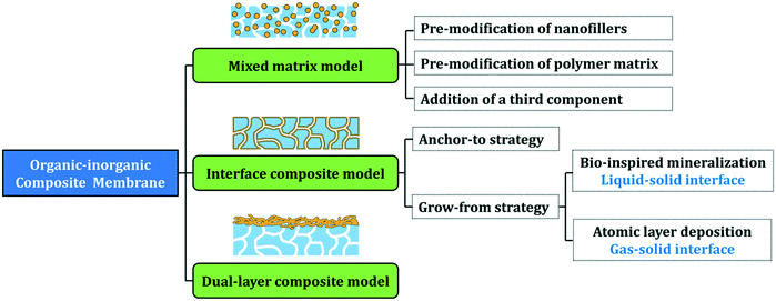
In 2016, we presented a comprehensive review on the surface and interface engineering of organic–inorganic composite membranes. Here, we are updating this perspective by outlining the most recent advances in this field, focusing on organic–inorganic interfaces from the view of molecular engineering. Three typical models of organic–inorganic membranes, i.e. mixed matrix models, interface composite models, and dual-layer composite models are discussed, and the interfacial engineering principles for each model are presented in the following sections (Fig. 1). We hope that this review will be a guide for membrane researchers and, moreover, the interface molecular engineering strategies outlined herein can be also extended to other composite material fabrication fields.
2. Molecular interfacial engineering of mixed matrix membranes
The most direct way to fabricate an organic–inorganic composite membrane is to blend two components and cast the mixture on an interface. However, poor compatibility arising from the polarity differences between inorganic nanofillers and polymers normally leads to nanoparticle (NPs) aggregation. Specifically, the incorporated particles are usually highly polar because of abundant polar moieties on their surface, while some commercial polymer membranes, such as polyethylene (PE), polypropylene (PP), and polytetrafluoroethylene (PTFE), have a nonpolar nature. One strategy to improve the interfacial compatibility is to eliminate the undesired “differences” between the inorganic component and polymer matrix, representing one of the most important targets of molecular engineering for organic–inorganic interfaces. Moreover, through molecular interfacial engineering, the composite membranes can exhibit superior performance and function.2.1. Pre-modification of nanofillers
One of the most popular strategies to promote organic–inorganic interfaces is surface modification of inorganic nanofillers. Some researchers have modified nanofillers with functional moieties for better compatibility or enhanced performance. In early research, modified inorganics such as Al2O3, SiO2 and TiO2 nanoparticles were incorporated into membrane matrices for better performance. Recently, nanomaterials such as CNTs and GOs have received great attention in organic–inorganic composite membrane fabrication. For instance, in an early study, Badawi functionalized multiwalled CNTs (MWCNTs) with carboxyl groups to improve their dispersion in CA membranes, which promoted the water purification performance of the composite membrane.23 Ayyaru et al. functionalized GOs with sulfonic acid groups, and blended them with polyvinylidene fluoride (PVDF) and polyvinylpyrrolidone (PVP) to fabricate a sulfonated GO (SGO)/PVDF composite ultrafiltration membrane through a conventional phase inversion process.24 Compared to the pristine PVDF and the unmodified GO/PVDF composite membranes, both the permeability and anti-fouling properties of the obtained membranes were significantly improved due to the substitutional sulfonic acid groups with a robust and thick hydration layer. Moreover, a significant improvement in permeability was achieved at a relatively low amount of SGO, avoiding aggregation of the filler. Silane coupling agents terminated with functional moieties were the ones most used to modify the inorganic fillers in the previous mixed matrix membranes. These coupling agents could interact or react with polymer matrices, creating linkages between the fillers, like zeolites, and the matrix.25–27Besides moiety modification, another common strategy is to graft polymer chains onto particles to promote interfacial compatibility or endow with novel functionality. As illustrative examples, poly(methylmethacrylate) (PMMA) was grafted on inorganic NPs because of its good compatibility with PVDF,28 and polyhydroxyethylmethacrylate (PHEMA) has served as a grafted polymer in polyethersulfone (PES) and polysulfone (PSf) composite membrane formation.29–31 Other polymer chains such as poly(acrylic acid) (PAA), hyperbranched poly(amine-ester) and polyethyleneimine (PEI) were also grafted onto nanofillers to improve the dispersion in mixed matrix membranes.32–35
The polymer component in membrane matrices will, clearly, show the best compatibility with itself, so some researchers have grafted matrix polymers onto nanofillers. For example, Bounos et al. blended PP-grafted MWCNTs with isotactic PP to fabricate a mixed matrix membrane.36 The grafted PP chains have the same characteristics as the isotactic PP matrix, which virtually eliminates the distinction between the particles and the polymer matrix and remarkably promotes their compatibility. The water vapor permeability of the composite membrane was selectively enhanced, which was attributed to the good dispersion of MWCNTs in the surrounding matrix interphase region (Fig. 2a and b). However, in most cases, the target of blending nanofillers is to improve the hydrophilicity of membranes, and surface grafting might mask the intrinsic properties, such as hydrophilicity of the nanofillers.
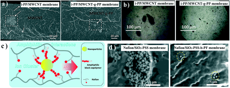 | ||
| Fig. 2 a) Cross-sectional SEM images and b) optical micrographs of the i-PP/MWCNT membrane and i-PP/MWCNT-g-PP membrane. c) Schematic illustration of the interaction between Nafion and amphiphilic block copolymer grafted nanoparticles. d) Cross-sectional SEM images of Nafion/SiO2-PSS and Nafion/SiO2-PSS-b-PF membranes. Reproduced with permission from ref. 36 and 38. Copyright 2017 and 2018, Elsevier. | ||
A creative solution to this challenge is to graft amphiphilic block copolymer chains to NPs. In these systems, a non-polar block is compatible with a matrix, while a polar block provides hydrophilic groups for enhancing membrane performance.30 Ag NPs were pre-modified with amphiphilic polyacrylonitrile (PAN)-co-PAA to fabricate an antifouling ultrafiltration membrane.37 He et al. modified SiO2 NPs with sulfonated polystyrene-block-polyperfluroallybenzene (PSS-b-PF), and blended them with Nafion to prepare a mixed-matrix polyelectrolyte membrane.38 Nafion, to some extent, is also amphiphilic because of its hydrophilic –SO3H and hydrophobic fluorinated chains, reflecting the relationships of the copolymer grafted on NPs (Fig. 2c). Similar properties facilitated the assembly of NPs and Nafion (Fig. 2d), which also promoted the reorganization of ion clusters.
As mentioned above, besides enhancing interface compatibility, some surface grafting methods are intended to promote membrane performance. Zwitterionic polymer-modified MoS2 nanosheets were synthesized and blended into a PES-based composite membrane.39 In that example, the MoS2 sheet served as a carrier to bring the hydrophilic zwitterionic polymer into the membrane for enhanced flux, while MoS2 itself could also adjust the sieving properties of the membrane. This molecular engineering is similar to the modified SiO2 NPs mentioned above, in that it not only improves the interfacial compatibility but also endows the membranes with other synergistic effects.
In contrast to surface grafting and moiety modification, functionalizing nanofillers with a third nano-sized inorganic component by in situ generation/growth is an emerging strategy, providing a tunable and efficient approach to reduce agglomeration and enable advanced functionality. For instance, metal hydroxide was structured on the surface of conventional zeolite to improve interfacial adhesion,40,41 and mineral inorganics were uniformly coated on nanomaterials, serving as a space layer to interact better with polymer matrices.42,43 In recent research studies, Zhang and co-workers innovatively developed a high-performance catalytic composite membrane through introducing Fe3O4@SiO2 NPs into PES polymer matrices.44 They coated the Fe3O4 NPs with SiO2via the hydrolysis of tetraethyl orthosilicate (TEOS). In the core–shell structure of Fe3O4@SiO2 NPs, the Fe3O4 core could serve as a Fenton-like reaction catalyst while the SiO2 shell is a hydrophilic surface layer (Fig. 3a). On account of this hydrophilic modification, the aggregation of Fe3O4 NPs was overcome, leading to effective dispersion in the polymer matrix. Moreover, the SiO2 layer accelerated electron migration in the catalytic activity under mild conditions, and also improved the ability of radicals to catch organic pollutants. Aiming at the further inhibition of aggregation, 3-aminopropyltriothoxysilane, a silane coupling agent, was anchored on the silica surface via covalent bonds. After the modification, both permeability and porosity were improved, and the composite catalytic membrane showed high flux. Chung et al. decorated ZnO NPs onto GO nanosheets through a sol–gel process and then blended them into PSf membranes.45 In that study, GO nanosheets acted as a platform to force the dispersion of ZnO NPs by pre-immobilization, and the ZnO-decorated GO could be well dispersed in the membrane matrix (Fig. 3b). The results show that the membrane properties are improved after the functionalization, including the permeability, humic acid rejection, antifouling, and antibacterial properties.
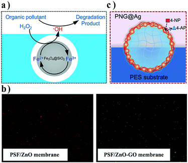 | ||
| Fig. 3 a) Schematic illustration of Fe3O4@SiO2 NPs in a membrane; b) FESEM mapping images of PSF/ZnO and PSF/ZnO–GO membranes and c) schematic illustration of the Ag-loaded nanogel at the membrane/feed interface. Reproduced with permission from ref. 44–46. Copyright 2019 and 2017, Elsevier; Copyright 2018, Wiley-VCH Verlag GmbH & Co. KGaA. | ||
An alternative strategy is to use organic–inorganic composite nanofillers instead of inorganic ones to alleviate the incompatibility at interfaces. Organic nanofillers that are compatible with polymer matrices serve as a carrier to bring inorganic components into a composite membrane. For example, Ag NPs were immobilized on thermo-responsive poly(N-isopropylacrylamide) (PNIPAM) nanogel surfaces based on a polydopamine (PDA) coating, and then blended into PES casting solution to fabricate a catalytic membrane via vapor-induced phase separation (Fig. 3c).46 The Ag-loaded nanogels were distributed on the membrane pore walls, and thereby membrane permeability could be adjusted by temperature to achieve optimal catalytic performance. Such PNIPAM nanogels assembled at the pore/matrix interfaces show excellent stability during long-term operation because of their strong compatibility.
2.2. Pre-modification of polymers or addition of a third component
Pre-modification of polymers with functional groups, specific side chains, or blocks is another effective way to promote interfacial compatibility between inorganic and organic components. Polar groups like sulfonic acid or carboxyl groups have been grafted to polymer matrices, not only for hydrophilization, but also for providing active sites to capture inorganic components.47,48 For instance, sulfonated PSf was synthesized through facile electrophilic substitution and blended with TiO2 to fabricate an organic–inorganic composite membrane for the removal of toxic Cr(VI) in wastewater.49 The interfacial compatibility between PSf and TiO2 was improved because of their hydrogen bonds.Polymer side chains like PAA have also been grafted to polymer matrices. Zhang et al. developed a nanocomposite hollow fiber membrane based on PVDF grafted with PAA and TiO2 through a sol–gel process.50 PAA was grafted onto PVDF via irradiation polymerization by a 60Co γ-ray source. Due to the coordination interaction between Ti4+ and the carboxyl group of PAA, Ti4+ ions were enriched and formed TiO2 NPs in situ within the matrix. The as-prepared membrane exhibited a uniform distribution of TiO2, leading to extremely prominent water flux and antifouling properties.
Compared with the direct modification of polymer matrices, adding a third component into the matrix is more versatile and has been extensively used. The triblock copolymer PEO–PPO–PEO (Pluronic F12), which possesses segments that can interact with both the organic component and inorganic component, was introduced into the casting solution to enhance interfacial compatibility.51 Recently, Wang and co-workers added a third component, poly[hexafluorobutyl methacrylate]-poly[methacrylic acid]-poly[(2-(methacryloyloxy) ethyl)trimethyl ammonium chloride] (PHFBM-PMAA-PMTAC), as a multifunctional additive into a casting solution comprised of PVDF and AgNO3 to construct a composite membrane integrating active and passive antifouling processes.52 Ag+ ions were reduced with NaHB4 to generate Ag NPs simultaneously during non-solvent induced phase separation. The PHFBM segments were hydrophobic and compatible with the PVDF matrix due to similar fluorinated chains, while the PMAA segments and the PMTAC segments were both hydrophilic to enhance membrane surface wettability. Carboxyl groups from the PMAA segments could coordinate with Ag NPs robustly. Consequently, Ag NPs were well dispersed on the surface and in the matrix because of the entanglement effects with the polymer chains (Fig. 4a). Moreover, some Ag NPs would spontaneously segregate to the membrane surface with the hydrophilic segments during the membrane formation. These hydrophilic chains on the surface could improve the membrane permeability and endow the membrane with good fouling resistance. The prepared membrane exhibited antibacterial properties and antifouling properties synergistically. Though effective, a challenge lies in the design and synthesis of a specific new block copolymer for each distinctive nanocomposite membrane system. These syntheses may be complex and difficult to scale-up.
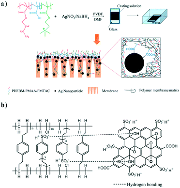 | ||
| Fig. 4 a) Fabrication process and structure of a PVDF/Ag/PHFBM-PMAA-PMTAC membrane. b) Schematic illustration of the interactions within an interpenetrating network/SGO composite membrane. Reproduced with permission from ref. 52 and 53. Copyright 2019 and 2018, Elsevier. | ||
In addition to the block copolymer used above, manifold cross-linked agents are also used as the third component to fabricate a network with the aim of immobilizing nanofillers. For example, Rajput et al. added styrene and divinylbenzene into poly(vinyl chloride) (PVC) solution and initiated their polymerization with azobisisobutyronitrile (AIBN) to form an interpenetrating network, and then utilized SGO as nanofillers to synthesize a cation exchange membrane for desalination via electrodialysis.53 The interpenetrating network between PVC chains improved the thermal and mechanical stability of the membrane. In order to further enhance ion-exchange capacity and reduce the aggregation of SGO, they sulfonated the prepared membrane using chlorosulfonic acid. SGO became more stable in the polymer matrix, and its dispersibility was greatly improved, which benefited from the hydrogen bonds formed between SGO and sulfonated styrene of the interpenetrating network (Fig. 4b). Some dispersants or compatibilizers like PVP were often added into the casting solution to reduce the aggregation of nanofillers.54,55 Except for the synthetic polymers, natural polymers such as polysaccharide normally have more polar groups which can serve as interacting sites. Nanofillers could be stabilized by adding a third component like polyethylene glycol,56 a cationic polymer57 or sulfonated chitosan58 that will form interactions with both nanofillers and polymers.
3. Molecular interfacial engineering of interface composite membranes
Compositing inorganic components onto as-formed membranes is another approach toward organic–inorganic composite membranes, and we first proposed the concept of an “interfacial composite membrane” in 2016,59 which refers to a composite membrane with inorganics located on the membrane surfaces (including the pore walls). Compared with blending inorganic components into casting solution, this method can achieve a higher inorganic surface coverage. The biggest challenge to integrate inorganic nanomaterials with polymer membranes lies in the poor interfacial compatibility between organic and inorganic components, and molecular engineering of the organic–inorganic interface provides an effective way to address this issue.In this section, we summarize two mainstream protocols, “anchor-to” and “grow-from,” which enhance the organic–inorganic interface in composite membranes and present the most recent advances in this field.
3.1. “Anchor-to” strategies
The “anchor-to” strategy is to engineer the polymer surface and/or inorganic particle surface with “donor” and “receptor” moieties, creating a strong and specific linkage at the organic–inorganic interface. The specific interactions include electrostatic interactions, hydrogen bonds, coordination, or even covalent bonding.In some early studies, sulfonic acid groups were introduced onto commercial PES membranes as anchoring sites to capture TiO2 NPs.60,61 Then, Elimelech's group presented a series of interface composite membranes based on “anchor-to” strategies. They modified PSf ultrafiltration membranes with reactive and/or charged functional moieties via oxygen plasma activation and incubated the obtained membrane in a solution containing PEI-grafted Ag NPs.62 Robust electrostatic and covalent bonds formed between the amines from PEI and the carboxyl moieties on the membrane surface after plasma treatment. In another example, using PVDF ultrafiltration membranes, the same group grafted negatively charged PMAA chains onto the PVDF membrane surface via plasma-induced grafting polymerization, and similarly immersed the plasma treated membrane into the amino-grafted SiO2 NP solution.63 Carboxyl moieties on PMAA acted as the binding sites to attract amino-grafted SiO2 NPs. These examples required pre-modification or pre-treatment of both membrane surfaces and inorganic nanomaterials. Elimelech et al. also demonstrated a facile and scalable approach to anchor bare SiO2 NPs onto an alkaline-treated PVDF membrane surface grafted with (3-aminopropyl)triethoxysilane.64 In a later study, a hydroxylated PVDF membrane surface was grafted with trimesoyl chloride, which reacted with Si-OH groups to anchor Ag/SiO2 nanocomposites for antifouling and antibacterial properties.65 Functional complexes like polyoxometalate could be also immobilized onto the membranes through the “anchor-to” strategy (Fig. 5a).66
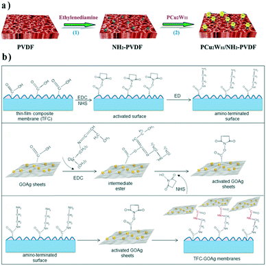 | ||
| Fig. 5 Fabrication process of a) the PCu2W11/NH2-PVDF interface composite membrane and b) binding GO–Ag nanosheets on the TFC membrane. Reproduced with permission from ref. 66 and 67. Copyright 2017, Elsevier. | ||
Recently, the “anchor-to” strategy was employed in developing organic–inorganic thin-film composite (TFC) membranes. For instance, GO–Ag NP composites, with well-known anti-microorganism activity, were covalently connected onto a polyamide top layer via amide bonds.67 Both nanocomposite and polyamide surfaces were pre-modified with carboxyl groups. After grafting ethylene diamine on TFC membranes through EDC/NHS mediation, EDC/NHS activated GO–Ag composites were then linked to the membrane surface (Fig. 5b).
However, limits of the “anchor-to” strategy lie in the arduous process of engineering “donor” and “receptor” moieties and effects of the reaction site density on the inorganic coverage. Moreover, the diffusion of NPs into the inner pores of membranes is difficult when the particle size is close to the pore size; in such cases, inorganics are only composited on the top surface rather than the pore walls.
3.2. “Grow-from” strategies
In situ growth of inorganic components from membrane surfaces provides a “bottom-up” strategy that can tailor inorganic layers more easily. The growth of minerals can be realized at the liquid–solid interface (e.g. bio-inspired mineralization) or the gas–solid interface (e.g. atomic layer deposition).Xu's group first proposed a bio-inspired mineralization strategy to fabricate organic–inorganic composite membranes.68–73 Inspired by bio-mineralization, an intermediate layer that can interact with mineral precursors is first constructed on the membrane to enrich the precursors and initiate mineralization. The first example was CaCO3-coated PP microfiltration membranes based on the interaction between Ca2+ and –COO− from PAA pre-grafted on the membrane (Fig. 6).68 The PAA intermediate layer could not only provide binding sites for CaCO3 growth but also stabilize the amorphous CaCO3 to control the mineral layer thickness. Following that pioneering work, the same group developed a series of mineralized membranes based on a multifunctional mussel-inspired intermediate layer. The PDA/PEI layer74 can provide positive amino groups for silicification (Fig. 6),71 and catechol groups for chelating metal ions.70 Rigid hydrophilic mineral coatings showed excellent anti-oil properties in water, enabling these mineralized membranes to be used in oil-in-water emulsion separation. Such properties are also desirable in Li-ion battery separators to improve electrolyte wetting and resist thermal shrinkage.75
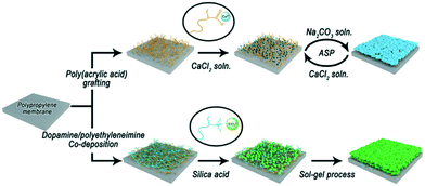 | ||
| Fig. 6 Typical processes of bioinspired mineralization for interface composite membrane construction. | ||
Since the original work by Xu's group, PDA-based interlayers have been widely applied to construct organic–inorganic composite membranes. For example, Cui and co-workers grew nickel cobalt layered double hydroxide (NiCo-LDH) on a PDA-modified PVDF membrane via a facile and low-temperature hydrothermal method (Fig. 7a).76 Catechol groups from the PDA layer could chelate Co2+ and Ni2+ ions, initiating the growth of a NiCo-LDH nanoarray. Its tunable grass-like surface structure promoted hydrophilicity and underwater oleophobicity of the membrane, making it suitable for oil–water emulsion separation. The enhanced interface compatibility between NiCo-LDH and PVDF endowed the composite membrane with outstanding recycling performance.
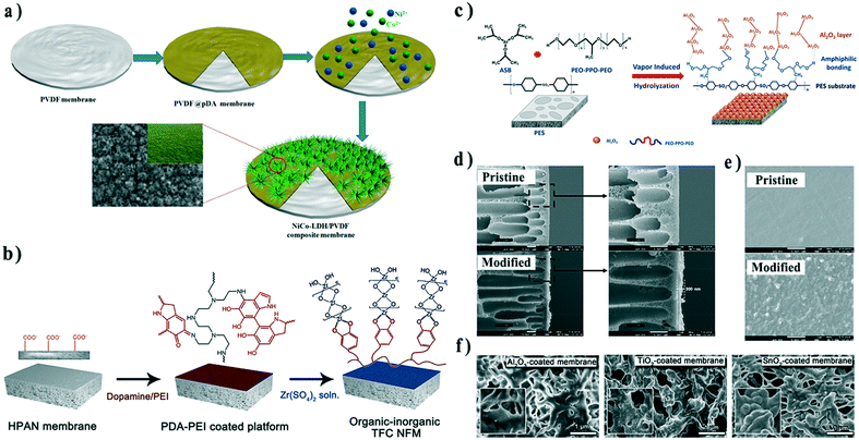 | ||
| Fig. 7 Schematic illustration of the fabrication process of a) the NiCo-LDH/PVDF interface composite membrane, b) ZrO2/PAN TFC membrane, and c) Al2O3/PES composite hollow fiber membrane. d) Cross-sectional and e) surface SEM images of pristine and Al2O3/PES composite hollow fiber membranes. f) SEM images of PVDF membranes coated with Al2O3, TiO2, and SnO2 by ALD. Reproduced with permission from ref. 76, 77, 80, and 86. Copyright 2019, 2016, and 2017, Elsevier; copyright 2018, American Chemical Society. | ||
Mineralization strategies have been also applied to fabricate organic–inorganic TFC membranes. For example, Lv et al. grew ZrO2 on PDA/PEI-deposited substrates to enhance structural stability during nanofiltration (Fig. 7b).77 In another example, Ding et al. deposited positively charged chitosan on PDA-modified PSf substrates via electrostatic interaction, and then initiated the hydrolysis through the Stöber method.78 Compared with a single intermediate PDA layer, an additional positively charged CS layer overcame the partial congregating of PDA and served as a smooth platform for uniform in situ growth of SiO2, leading to a dense and defect-free inorganic layer.
Inorganic layers can also be further modified to realize even more sophisticated functionality. Wongchitphimon et al. modified Matrimid® membranes with trimethoxysilane to introduce amide groups on the membrane surface, and subsequently immersed the membrane in TEOS for silicification.79 Consequently, the membrane was grafted with fluorinated silane to achieve a non-wetting state, which displayed bright prospects in the recovery of methane dissolved in anaerobic effluent.
In addition, Lin and co-workers immersed PES hollow fiber membranes in a mixed solution composed of an Al2O3 precursor, aluminum-tri-sec-butoxide (ASB), and a tri-block copolymer, PEO–PPO–PEO. A uniform and continuous Al2O3 layer could be easily achieved by in situ vapor-induced hydrolyzation (Fig. 7c–e).80 The structure and performance of the membrane could be adjusted by the amount of ABS. In this research, the amphiphilic PEO–PPO–PEO played a vital role in bridging the substrate and precursors. The PPO segments would be attracted by PES through hydrophobic interactions, while the PEO segments could capture the precursor by hydrogen bonds.81,82 PEO–PPO–PEO provided growth sites for Al2O3, improving the affinity of inorganics to the organic substrate, and addressed the issue of poor interface compatibility.
Atomic layer deposition (ALD) is another appealing technique to construct adaptable and uniform inorganic coatings on polymeric membranes.83 In a typical ALD process, reactive precursor vapors are pulsed into a chamber alternately under the protection of inert gas, leading to the layer-by-layer growth of metals, metal oxides, and even organic materials.84,85 Our recent research demonstrated the deposition of a series of oxides, including ZnO, Al2O3, TiO2, and SnO2, on PVDF membranes (Fig. 7f). ALD provided the best strategy to construct various inorganic layers with controllable thickness, which could be used to investigate the anti-crude-oil properties of different oxides.86 In our research, PVP added in commercial membranes provided nucleation sites for ALD eliminating the need for surface pre-treatment. However, for certain extremely inert substrate materials (e.g. PP or PTFE), ALD nucleation becomes difficult and particles instead of a uniform coating form. Both plasma and nitric acid activation have been proposed to facilitate the ALD process in such scenarios.87–89 In addition, the ALD layer can also serve as an intermediate layer for further modification.90,91 More examples could be found in our recent review.83
4. Molecular interfacial engineering of dual-layer composite membranes
Distinct from interface composite membranes, there is another kind of composite membrane with a macroscopic inorganic layer and a polymer layer, which is typically fabricated by vacuum filtration of inorganic nanomaterial suspension through a polymer membrane. The inorganic materials are rejected by membrane pores and form a filtration cake layer on the membrane surface. These composited membranes are named “dual-layer composite membranes” in this review. In such membranes, a polymer substrate serves as a support layer, while the inorganic layer plays a crucial role in separation or other functions. The inorganic nanomaterials could be NPs,92 nanowires,93 nanotubes,94 or nanosheets.95 As with other composite membranes, stability between the two layers is a persistent challenge, especially under cross-flow operation. Therefore, some interface molecular engineering methods have been conducted to enhance the interface strength, and herein we provide several examples to present the recent advances in this field.Pre-modification of the support and/or inorganic layers is another approach for promoting interfacial compatibility. For example, Li et al. modified TiO2 NPs with PEI and deposited the modified NPs onto the surface of PDA-coated PAN ultrafiltration membranes via vacuum filtration.92 PDA could interact and even react with PEI to stabilize the particle layer on the membrane surface. Ag NP layers were further synthesized on the particle layers to endow the membranes with anti-bacterial activity (Fig. 8a). In these membranes, the PDA layer served as the adhesive layer to connect the substrate and TiO2 NPs, the PEI–TiO2 layer acted as the separation layer, and the Ag NP layer provided the antibacterial function.
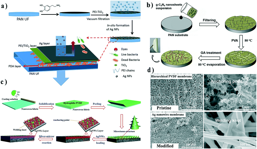 | ||
| Fig. 8 Fabrication process of a) the PEI–TiO2/Ag composite PAN membrane, b) g-C3N4 nanosheet dual-layer composite membrane, and c) Ag nanowire dual-layer composite membrane. d) SEM images of pristine hierarchical PVDF membrane and Ag nanowire membrane surfaces after the silver-mirror reaction. Reproduced with permission from ref. 92, 93 and 96. Copyright 2019, Elsevier; Copyright 2018, Wiley-VCH Verlag GmbH & Co. KGaA. | ||
Another strategy is to add a third component to connect/enclose inorganic nanomaterials with a support layer. Li et al. filtered graphitic carbon nitride (g-C3N4) nanosheets on PAN substrate surfaces and then stabilized the nanosheet layer by constructing a cross-linked network from polyvinyl alcohol and glutaric dialdehyde, which prevented the detachment or damage of nanosheets (Fig. 8b).96
Combining the above strategies, Xiong and co-workers developed a robust multi-functional composite membrane by weaving an adjacent interconnected Ag nanowire (Ag NW) network on a PVDF membrane surface inspired by Chinese knots (Fig. 8c).93 The PVDF substrate was pre-designed with a micro/nano-hierarchical surface during the phase-inversion process. Compared with smooth membrane surfaces, structured surfaces could provide more anchoring points for attaching the Ag NWs.97,98 After filtration of Ag NWs onto the membrane surface, the silver mirror reaction was conducted to integrate the deposited Ag NWs and tighten the connection between the Ag NW layer and membrane (Fig. 8d).
Conclusions and perspective
Benefiting from the enhanced performance and special functions granted by inorganic components, organic–inorganic membranes have attracted burgeoning attention in water technology. Since organic–inorganic interfaces are vital for these membranes, tremendous effort has been devoted to improving interface compatibility through molecular engineering strategies. In this review, we summarized molecular engineering strategies toward interface control in three classes of organic–inorganic composite membranes. In mixed matrix membranes, molecular engineering is generally completed before membrane formation. Inorganic fillers or/and polymer matrices were pre-modified with small molecules or polymer chains to achieve a more compatible interface during the phase-separation process. A third component could also serve as an amphiphilic link to stabilize the incompatible interface. In interface composite membranes, the “anchor-to” and “grow-from” strategies were proposed to construct an inorganic layer on the surface of a polymer skeleton. The former engineers the as-prepared nanomaterials and/or polymer surface to realize a “donor–receptor” interaction. In contrast, the latter tries to in situ grow a mineral layer at a liquid–solid or gas–solid interface, which is more controllable in thickness and inorganic coverage. In dual-layer composite membranes, interfacial engineering is most likely to provide a robust connection between the organic and inorganic layers for enhanced stability in a cross-flow cell. Both covalent/non-covalent interactions and interlocking structures can achieve this goal by molecular or structural design.Despite these recent advances in organic–inorganic membranes, there are still some challenges on the road to the industrial production of these membranes. Firstly, high inorganic coverage and significant performance improvement could be easily achieved by some interface composite strategies (e.g. ALD and bio-inspired mineralization). However, the sometimes high fabrication cost, complicated process, or expensive facilities limit their practical applications on the large scales necessary for real-world water treatment. More economical and scalable techniques are highly desirable. Secondly, even for the mixed matrix membranes, large-scale engineering of inorganic nanomaterials remains challenging and uneconomic. Thirdly, most of the dual-layer composite membranes are fabricated by vacuum filtration, which can be only conducted on the laboratory scale. From a foundational perspective, how the interfacial interactions affect the membrane formation on the micro-scale is still unclear, which is critical for understanding the structure–performance relationships and ultimately designing optimized organic–inorganic composite membranes. Except for addressing the above-mentioned challenges, future research opportunities also lie in developing novel membranes. For example, the Janus membrane is an emerging concept of a membrane with opposing properties on each side, which can find widespread applications in multiphase processes.99,100 An organic–inorganic Janus membrane was developed to quickly separate trace blood for glucose measurement.101 Inorganics can bring fantastic properties to this class of membranes.
Conflicts of interest
There are no conflicts to declare.Acknowledgements
This work was supported as part of the Advanced Materials for Energy-Water Systems (AMEWS) Center, an Energy Frontier Research Center funded by the U.S. Department of Energy, Office of Science, Basic Energy Sciences. S.-L. Wu, F. Liu, and H.-C. Yang also acknowledge financial support from the National Natural Science Foundation of China (51909291) and the Fundamental Research Funds for the Central Universities (19lgzd17).Notes and references
- A. Lee, J. W. Elam and S. B. Darling, Environ. Sci.: Water Res. Technol., 2016, 2, 17–42 RSC.
- M. Elimelech and W. A. Phillip, Science, 2011, 333, 712–717 CrossRef CAS PubMed.
- J. R. Werber, C. O. Osuji and M. Elimelech, Nat. Rev. Mater., 2016, 1, 16018 CrossRef CAS.
- M. A. Shannon, P. W. Bohn, M. Elimelech, J. G. Georgiadis, B. J. Marinas and A. M. Mayes, Nature, 2008, 452, 301–310 CrossRef CAS PubMed.
- L. Y. Ng, A. W. Mohammad, C. P. Leo and N. Hilal, Desalination, 2013, 308, 15–33 CrossRef CAS.
- S. Kim, H. Wang and Y. M. Lee, Angew. Chem., Int. Ed., 2019, 58, 2–18 CrossRef.
- Y. Cheng, Y. Ying, S. Japip, S. D. Jiang, T. S. Chung, S. Zhang and D. Zhao, Adv. Mater., 2018, 30, 1802401 CrossRef PubMed.
- S. B. Darling, J. Appl. Phys., 2018, 124, 030901 CrossRef.
- I. Goossens and A. Van Haute, Desalination, 1976, 18, 203–214 CrossRef CAS.
- D. Q. Vu, W. J. Koros and S. J. Miller, J. Membr. Sci., 2003, 211, 311–334 CrossRef CAS.
- T. S. Chung, L. Y. Jiang, Y. Li and S. Kulprathipanja, Prog. Polym. Sci., 2007, 32, 483–507 CrossRef CAS.
- M. A. Aroon, A. F. Ismail, T. Matsuura and M. M. Montazer-Rahmati, Sep. Purif. Technol., 2010, 75, 229–242 CrossRef CAS.
- M. Smaïhi, T. Jermoumi, J. Marignan and R. D. Noble, J. Membr. Sci., 1996, 116, 211–220 CrossRef.
- I. Genné, S. Kuypers and R. Leysen, J. Membr. Sci., 1996, 113, 343–350 CrossRef.
- T. H. Bae and T. M. Tak, J. Membr. Sci., 2005, 249, 1–8 CrossRef CAS.
- L. Yan, Y. S. Li, C. B. Xiang and S. Xianda, J. Membr. Sci., 2006, 276, 162–167 CrossRef CAS.
- S. Zinadini, A. A. Zinatizadeh, M. Rahimi, V. Vatanpour and H. Zangeneh, J. Membr. Sci., 2014, 453, 292–301 CrossRef CAS.
- V. Vatanpour, S. S. Madaeni, R. Moradian, S. Zinadini and B. Astinchap, J. Membr. Sci., 2011, 375, 284–294 CrossRef CAS.
- S. J. You, G. U. Semblante, S. C. Lu, R. A. Damodar and T. C. Wei, J. Hazard. Mater., 2012, 237–238, 10–19 CrossRef CAS PubMed.
- C. E. Ren, K. B. Hatzell, M. Alhabeb, Z. Ling, K. A. Mahmoud and Y. Gogotsi, J. Phys. Chem. Lett., 2015, 6, 4026–4031 CrossRef CAS PubMed.
- R. Zhang, Y. Liu, M. He, Y. Su, X. Zhao, M. Elimelech and Z. Jiang, Chem. Soc. Rev., 2016, 45, 5888–5924 RSC.
- D. J. Miller, D. R. Dreyer, C. W. Bielawski, D. R. Paul and B. D. Freeman, Angew. Chem., Int. Ed., 2017, 56, 4662–4711 CrossRef CAS PubMed.
- N. El Badawi, A. R. Ramadan, A. M. K. Esawi and M. El-Morsi, Desalination, 2014, 344, 79–85 CrossRef CAS.
- S. Ayyaru and Y.-H. Ahn, J. Membr. Sci., 2017, 525, 210–219 CrossRef CAS.
- H. Sun, L. Lu, X. Chen and Z. Jiang, Appl. Surf. Sci., 2008, 254, 5367–5374 CrossRef CAS.
- G. Liu, F. Xiangli, W. Wei, S. Liu and W. Jin, Chem. Eng. J., 2011, 174, 495–503 CrossRef CAS.
- L. Ji, B. Shi and L. Wang, J. Appl. Polym. Sci., 2015, 132, 1–9 CrossRef.
- S.-H. Zhi, R. Deng, J. Xu, L.-S. Wan and Z.-K. Xu, React. Funct. Polym., 2015, 86, 184–190 CrossRef CAS.
- L.-J. Zhu, L.-P. Zhu, J.-H. Jiang, Z. Yi, Y.-F. Zhao, B.-K. Zhu and Y.-Y. Xu, J. Membr. Sci., 2014, 451, 157–168 CrossRef CAS.
- S. H. Zhi, J. Xu, R. Deng, L. S. Wan and Z. K. Xu, Polymer, 2014, 55, 1333–1340 CrossRef CAS.
- G. Zhang, S. Lu, L. Zhang, Q. Meng, C. Shen and J. Zhang, J. Membr. Sci., 2013, 436, 163–173 CrossRef CAS.
- X. Zhao, J. Ma, Z. Wang, G. Wen, J. Jiang, F. Shi and L. Sheng, Desalination, 2012, 303, 29–38 CrossRef CAS.
- P. Daraei, S. S. Madaeni, N. Ghaemi, H. Ahmadi Monfared and M. A. Khadivi, Sep. Purif. Technol., 2013, 104, 32–44 CrossRef CAS.
- L. Yu, Y. Zhang, B. Zhang, J. Liu, H. Zhang and C. Song, J. Membr. Sci., 2013, 447, 452–462 CrossRef CAS.
- P. Daraei, S. S. Madaeni, N. Ghaemi, M. A. Khadivi, L. Rajabi, A. A. Derakhshan and F. Seyedpour, Chem. Eng. J., 2013, 221, 111–123 CrossRef CAS.
- G. Bounos, K. S. Andrikopoulos, H. Moschopoulou, G. C. Lainioti, D. Roilo, R. Checchetto, T. Ioannides, J. K. Kallitsis and G. A. Voyiatzis, J. Membr. Sci., 2017, 524, 576–584 CrossRef CAS.
- S. K. Jewrajka and S. Haldar, Polym. Compos., 2016, 37, 915–924 CrossRef.
- G. He, J. Zhao, C. Chang, M. Xu, S. Wang, S. Jiang, Z. Li, X. He, X. Wu and Z. Jiang, J. Membr. Sci., 2018, 563, 1–9 CrossRef CAS.
- X. Liang, P. Wang, J. Wang, Y. Zhang, W. Wu, J. Liu and B. Van der Bruggen, J. Membr. Sci., 2019, 573, 270–279 CrossRef CAS.
- S. Shu, S. Husain and W. J. Koros, J. Phys. Chem. C, 2007, 111, 652–657 CrossRef CAS.
- T. H. Bae, L. Junqiang, S. L. Jong, W. J. Koros, C. W. Jones and S. Nair, J. Am. Chem. Soc., 2009, 131, 14662–14663 CrossRef CAS.
- V. Vatanpour, S. S. Madaeni, R. Moradian, S. Zinadini and B. Astinchap, Sep. Purif. Technol., 2012, 90, 69–82 CrossRef CAS.
- H. Wu, B. Tang and P. Wu, J. Membr. Sci., 2014, 451, 94–102 CrossRef CAS.
- L.-P. Zhang, Z. Liu, Y. Faraj, Y. Zhao, R. Zhuang, R. Xie, X.-J. Ju, W. Wang and L.-Y. Chu, J. Membr. Sci., 2019, 573, 493–503 CrossRef CAS.
- Y. T. Chung, E. Mahmoudi, A. W. Mohammad, A. Benamor, D. Johnson and N. Hilal, Desalination, 2017, 402, 123–132 CrossRef CAS.
- R. Xie, F. Luo, L. Zhang, S. F. Guo, Z. Liu, X. J. Ju, W. Wang and L. Y. Chu, Small, 2018, 14, 1703650 CrossRef PubMed.
- Y. H. Su, Y. L. Liu, Y. M. Sun, J. Y. Lai, D. M. Wang, Y. Gao, B. Liu and M. D. Guiver, J. Membr. Sci., 2007, 296, 21–28 CrossRef CAS.
- R. Gosalawit, S. Chirachanchai, S. Shishatskiy and S. P. Nunes, J. Membr. Sci., 2008, 323, 337–346 CrossRef CAS.
- S. J. M, V. Nayak, M. Padaki, R. G. Balakrishna and K. Soontarapa, J. Hazard. Mater., 2017, 332, 112–123 CrossRef PubMed.
- F. Zhang, W. Zhang, Y. Yu, B. Deng, J. Li and J. Jin, J. Membr. Sci., 2013, 432, 25–32 CrossRef CAS.
- X. Li, X. Fang, R. Pang, J. Li, X. Sun, J. Shen, W. Han and L. Wang, J. Membr. Sci., 2014, 467, 226–235 CrossRef CAS.
- F. Wang, M. He, K. Gao, Y. Su, R. Zhang, Y. Liu, J. Shen, Z. Jiang and R. Kasher, J. Membr. Sci., 2019, 576, 150–160 CrossRef CAS.
- A. Rajput, V. Yadav, P. P. Sharma and V. Kulshrestha, J. Membr. Sci., 2018, 564, 44–52 CrossRef CAS.
- H. Basri, A. F. Ismail, M. Aziz, K. Nagai, T. Matsuura, M. S. Abdullah and B. C. Ng, Desalination, 2010, 261, 264–271 CrossRef CAS.
- H. Basri, A. F. Ismail and M. Aziz, Desalination, 2011, 273, 72–80 CrossRef CAS.
- A. Sabir, M. Shafiq, A. Islam, A. Sarwar, M. R. Dilshad, A. Shafeeq, M. T. Zahid Butt and T. Jamil, Carbohydr. Polym., 2015, 132, 589–597 CrossRef CAS PubMed.
- S. Varanasi, Z. X. Low and W. Batchelor, Chem. Eng. J., 2015, 265, 138–146 CrossRef CAS.
- A. Shirdast, A. Sharif and M. Abdollahi, J. Power Sources, 2016, 306, 541–551 CrossRef CAS.
- H.-C. Yang, J. Hou, V. Chen and Z.-K. Xu, J. Mater. Chem. A, 2016, 4, 9716–9729 RSC.
- T. H. Bae and T. M. Tak, J. Membr. Sci., 2005, 266, 1–5 CrossRef CAS.
- T. H. Bae, I. C. Kim and T. M. Tak, J. Membr. Sci., 2006, 275, 1–5 CrossRef CAS.
- M. S. Mauter, Y. Wang, K. C. Okemgbo, C. O. Osuji, E. P. Giannelis and M. Elimelech, ACS Appl. Mater. Interfaces, 2011, 3, 2861–2868 CrossRef CAS PubMed.
- S. Liang, Y. Kang, A. Tiraferri, E. P. Giannelis, X. Huang and M. Elimelech, ACS Appl. Mater. Interfaces, 2013, 5, 6694–6703 CrossRef CAS PubMed.
- C. Boo, J. Lee and M. Elimelech, Environ. Sci. Technol., 2016, 50, 12275–12282 CrossRef CAS PubMed.
- Y. Pan, Z. Yu, H. Shi, Q. Chen, G. Zeng, H. Di, X. Ren and Y. He, J. Chem. Technol. Biotechnol., 2017, 92, 562–572 CrossRef CAS.
- T. Lu, X. Xu, X. Liu and T. Sun, Chem. Eng. J., 2017, 308, 151–159 CrossRef CAS.
- A. F. Faria, C. Liu, M. Xie, F. Perreault, L. D. Nghiem, J. Ma and M. Elimelech, J. Membr. Sci., 2017, 525, 146–156 CrossRef CAS.
- P.-C. Chen, L.-S. Wan and Z.-K. Xu, J. Mater. Chem., 2012, 22, 22727–22733 RSC.
- P.-C. Chen and Z.-K. Xu, Sci. Rep., 2013, 3, 2776 CrossRef PubMed.
- H. C. Yang, Y. F. Chen, C. Ye, Y. N. Jin, H. Li and Z. K. Xu, Chem. Commun., 2015, 51, 12779–12782 RSC.
- H. C. Yang, J. K. Pi, K. J. Liao, H. Huang, Q. Y. Wu, X. J. Huang and Z. K. Xu, ACS Appl. Mater. Interfaces, 2014, 6, 12566–12572 CrossRef CAS PubMed.
- C. Zhang, H. C. Yang, L. S. Wan, H. Q. Liang, H. Li and Z. K. Xu, ACS Appl. Mater. Interfaces, 2015, 7, 11567–11574 CrossRef CAS PubMed.
- S.-H. Zhi, L.-S. Wan and Z.-K. Xu, J. Membr. Sci., 2014, 454, 144–154 CrossRef CAS.
- H.-C. Yang, K.-J. Liao, H. Huang, Q.-Y. Wu, L.-S. Wan and Z.-K. Xu, J. Mater. Chem. A, 2014, 2, 10225–10230 RSC.
- J. K. Pi, G. P. Wu, H. C. Yang, C. G. Arges and Z. K. Xu, ACS Appl. Mater. Interfaces, 2017, 9, 21971–21978 CrossRef CAS PubMed.
- J. Cui, Z. Zhou, A. Xie, Q. Wang, S. Liu, J. Lang, C. Li, Y. Yan and J. Dai, J. Membr. Sci., 2019, 573, 226–233 CrossRef CAS.
- Y. Lv, H.-C. Yang, H.-Q. Liang, L.-S. Wan and Z.-K. Xu, J. Membr. Sci., 2016, 500, 265–271 CrossRef CAS.
- W. Ding, H. Zhuo, M. Bao, Y. Li and J. Lu, Chem. Eng. J., 2017, 330, 337–344 CrossRef CAS.
- S. Wongchitphimon, W. Rongwong, C. Y. Chuah, R. Wang and T.-H. Bae, J. Membr. Sci., 2017, 540, 146–154 CrossRef CAS.
- Y. Lin, C. H. Loh, L. Shi, Y. Fan and R. Wang, J. Membr. Sci., 2017, 539, 65–75 CrossRef CAS.
- A. Qin, X. Li, X. Zhao, D. Liu and C. He, ACS Appl. Mater. Interfaces, 2015, 7, 8427–8436 CrossRef CAS PubMed.
- C. H. Loh and R. Wang, J. Membr. Sci., 2013, 446, 492–503 CrossRef CAS.
- H. C. Yang, R. Z. Waldman, Z. Chen and S. B. Darling, Nanoscale, 2018, 10, 20505–20513 RSC.
- M. Leskela and M. Ritala, Angew. Chem., Int. Ed., 2003, 42, 5548–5554 CrossRef CAS PubMed.
- G. M. Steven, Chem. Rev., 2010, 1, 111–131 Search PubMed.
- H. C. Yang, Y. Xie, H. Chan, B. Narayanan, L. Chen, R. Z. Waldman, S. Sankaranarayanan, J. W. Elam and S. B. Darling, ACS Nano, 2018, 12, 8678–8685 CrossRef CAS PubMed.
- Q. Xu, Y. Yang, J. Yang, X. Wang, Z. Wang and Y. Wang, J. Membr. Sci., 2013, 443, 62–68 CrossRef CAS.
- Q. Xu, J. Yang, J. Dai, Y. Yang, X. Chen and Y. Wang, J. Membr. Sci., 2013, 448, 215–222 CrossRef CAS.
- H. Chen, L. Kong and Y. Wang, J. Membr. Sci., 2015, 487, 109–116 CrossRef CAS.
- S. Xiong, L. Kong, J. Huang, X. Chen and Y. Wang, J. Membr. Sci., 2015, 493, 478–485 CrossRef CAS.
- S. Feng, D. Li, Z.-x. Low, Z. Liu, Z. Zhong, Y. Hu, Y. Wang and W. Xing, J. Membr. Sci., 2017, 531, 86–93 CrossRef CAS.
- J. Li, S. Yuan, J. Zhu and B. Van der Bruggen, Chem. Eng. J., 2019, 373, 275–284 CrossRef CAS.
- Z. Xiong, T. Li, F. Liu, H. Lin, Y. Zhong, Q. A. Meng, Q. Fang, H. Sakil and W. Song, Adv. Mater. Interfaces, 2018, 5, 1800183 CrossRef.
- Y. Wei, Y. Zhu and Y. Jiang, Chem. Eng. J., 2019, 356, 915–925 CrossRef CAS.
- X. He, L. Cao, G. He, A. Zhao, X. Mao, T. Huang, Y. Li, H. Wu, J. Sun and Z. Jiang, J. Mater. Chem. A, 2018, 6, 10277–10285 RSC.
- R. Li, Y. Ren, P. Zhao, J. Wang, J. Liu and Y. Zhang, J. Hazard. Mater., 2019, 365, 606–614 CrossRef CAS PubMed.
- Z. Xiong, H. Lin, Y. Zhong, Y. Qin, T. Li and F. Liu, J. Mater. Chem. A, 2017, 5, 6538–6545 RSC.
- Z. Xiong, H. Lin, F. Liu, P. Xiao, Z. Wu, T. Li and D. Li, Sci. Rep., 2017, 7, 14099 CrossRef PubMed.
- H. C. Yang, J. Hou, V. Chen and Z. K. Xu, Angew. Chem., Int. Ed., 2016, 55, 13398–13407 CrossRef CAS PubMed.
- H. C. Yang, Y. Xie, J. Hou, A. K. Cheetham, V. Chen and S. B. Darling, Adv. Mater., 2018, 30, 1801495 CrossRef.
- W. Zhang, L. Hu, H. Chen, S. Gao, X. Zhang and J. Jin, J. Mater. Chem. B, 2017, 5, 4876–4882 RSC.
| This journal is © The Royal Society of Chemistry 2020 |


